EP0276983A2 - Pump dispenser for viscous fluids - Google Patents
Pump dispenser for viscous fluids Download PDFInfo
- Publication number
- EP0276983A2 EP0276983A2 EP88300637A EP88300637A EP0276983A2 EP 0276983 A2 EP0276983 A2 EP 0276983A2 EP 88300637 A EP88300637 A EP 88300637A EP 88300637 A EP88300637 A EP 88300637A EP 0276983 A2 EP0276983 A2 EP 0276983A2
- Authority
- EP
- European Patent Office
- Prior art keywords
- product
- piston
- dispenser
- container body
- container
- Prior art date
- Legal status (The legal status is an assumption and is not a legal conclusion. Google has not performed a legal analysis and makes no representation as to the accuracy of the status listed.)
- Granted
Links
- 239000012530 fluid Substances 0.000 title description 4
- 238000005086 pumping Methods 0.000 claims abstract description 18
- 239000007788 liquid Substances 0.000 claims abstract description 16
- 230000007246 mechanism Effects 0.000 claims abstract description 16
- 230000007423 decrease Effects 0.000 claims abstract description 4
- 238000007599 discharging Methods 0.000 claims description 2
- 239000000047 product Substances 0.000 description 34
- 230000000694 effects Effects 0.000 description 6
- 230000000740 bleeding effect Effects 0.000 description 3
- 239000012263 liquid product Substances 0.000 description 2
- 239000006210 lotion Substances 0.000 description 2
- 239000000463 material Substances 0.000 description 2
- 230000009467 reduction Effects 0.000 description 2
- 238000007789 sealing Methods 0.000 description 2
- 241000238366 Cephalopoda Species 0.000 description 1
- 230000009471 action Effects 0.000 description 1
- 230000015572 biosynthetic process Effects 0.000 description 1
- 239000007894 caplet Substances 0.000 description 1
- 239000008294 cold cream Substances 0.000 description 1
- 239000006071 cream Substances 0.000 description 1
- 238000011038 discontinuous diafiltration by volume reduction Methods 0.000 description 1
- 238000006073 displacement reaction Methods 0.000 description 1
- 238000012986 modification Methods 0.000 description 1
- 230000004048 modification Effects 0.000 description 1
- 235000019271 petrolatum Nutrition 0.000 description 1
Images

Classifications
-
- B—PERFORMING OPERATIONS; TRANSPORTING
- B05—SPRAYING OR ATOMISING IN GENERAL; APPLYING FLUENT MATERIALS TO SURFACES, IN GENERAL
- B05B—SPRAYING APPARATUS; ATOMISING APPARATUS; NOZZLES
- B05B11/00—Single-unit hand-held apparatus in which flow of contents is produced by the muscular force of the operator at the moment of use
- B05B11/01—Single-unit hand-held apparatus in which flow of contents is produced by the muscular force of the operator at the moment of use characterised by the means producing the flow
- B05B11/02—Membranes or pistons acting on the contents inside the container, e.g. follower pistons
- B05B11/028—Pistons separating the content remaining in the container from the atmospheric air to compensate underpressure inside the container
-
- B—PERFORMING OPERATIONS; TRANSPORTING
- B05—SPRAYING OR ATOMISING IN GENERAL; APPLYING FLUENT MATERIALS TO SURFACES, IN GENERAL
- B05B—SPRAYING APPARATUS; ATOMISING APPARATUS; NOZZLES
- B05B11/00—Single-unit hand-held apparatus in which flow of contents is produced by the muscular force of the operator at the moment of use
- B05B11/01—Single-unit hand-held apparatus in which flow of contents is produced by the muscular force of the operator at the moment of use characterised by the means producing the flow
- B05B11/10—Pump arrangements for transferring the contents from the container to a pump chamber by a sucking effect and forcing the contents out through the dispensing nozzle
- B05B11/1001—Piston pumps
Definitions
- the present invention is a pump dispenser for viscous fluids, namely creams, lotions, and the like.
- the Prior art shows a variety of dispensers for fluid masses which comprise a generally tubular container with a pumping mechanism at one end and a take-up piston at the other.
- the pumping mechanism is adapted to dispense the product from the container.
- the take-up piston is moved by atmospheric pressure towards the pumping mechanism to insure that the fluid product and any associated reservoir in the pumping mechanism do not develop unwanted voids or open spaces which would interfere with the desired dispensing action on subsequent uses of the dispenser.
- One approach to the design of an appropriate pumping mechanism for one end of such containers is to provide a container body part which is resiliently compressible to effect a decrease in volume of a pumping chamber so as to cause the dispensing of product from the container.
- US Patent No. 4,301,948 to J Czech illustrates a pumping mechanism which comprises a head member in the form of a substantially cylindrical cap which is slidely supported on an outer side wall surface of the container. Movement of the head member towards the tubular container effects a reduction in a pump chamber containing the product to effect dispensing of the product through a suitable outlet in the head member.
- US Patent No. 4,323,175 to J Eckert illustrates a dispenser having a delivery device on the upper side of a supply container, transverse to the main direction in which the supply cosntainer extends.
- This delivery device has a cylinder space in which is arranged a displacement piston which is adapted to be displaced axially.
- US Patent No. 4,485,943 to J Czech shows a dispenser which utilises a spring-biased piston to effect an appropriate reduction in the volume of a pump chamber.
- the path of egress of the material from the pump chamber to the outlet first lies in a direction lateral to the path of travel of the piston and thence parallel to the path of travel of the piston but laterally displaced therefrom.
- the present invention is a viscous product dispenser which comprises: a generally tubular container body to hold the product; a take-up piston at the lower end of the body which responds to discharging of product from the container body by shifting its position towards the upper end of the body so as to decrease the internal volume of the container body holding the product by an amount corresponding to the volume of product discharged; and a bulk liquid pump dispenser at the upper portion of the container body which comprises an inlet for product extending into the container body portion, intended to hold the product and a finger-depressible, spring-biased piston/cylinder pumping mechanism located within.
- the liquid pump dispenser has a product outlet conduit which is parallel to the axis defining the inlet for product from the container into the pump dispenser.
- the product outlet conduit within the pump dispenser is substantially coaxial with the centre of the piston in the pumping mechanism.
- the piston in the pumping mechanism which is movable towards and away from a reservoir within the cylinder encasing it, is substantially smaller in width than the internal width of the tubular container.
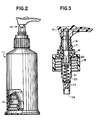
- FIG. 1 illustrates, in perspective, the three major elements of the container of the present invention. These elements are novel, in combination, although the individual elements themselves are conventional.
- the first element is a tubular container 11 having a suitable outlet opening 12 at its upper end.
- This tubular container at its opposed open end, is adapted to receive a take-up piston 13 which, under the influence of atmospheric pressure, is urged in an upward direction towards the outlet as product is pumped from the inside of the container 11.
- the combination of tubular container 11 and take-up piston 13 is broadly known as indicated by the various US patents referenced hereinbefore. Further details regarding this combination can be found therein.
- the point of novelty for the present container relates to the use of a bulk liquid pump dispenser 14 rather than the various types of pumping mechanisms illustrated in the aforementioned US patents.
- This bulk liquid pump dispenser is also a conventional item but has not been used in connection with the combination of a tubular container 11 and a take-up piston 13 as described and claimed herein.
- the bulk liquid pump dispenser 14 used in connection with the present invention is utilised with containers that have a fixed bottom. Suitable liquid pump dispensers of this type are readily available from a number of commercial sources including Calmar Inc of Watchung, New Jersey.
- FIG. 3 illustrates this type of pump dispenser 14 in cross-section in more detail.
- the pump comprises an eductor head 15, a dispenser piston 16, an optional locking ring 17, a caplet 18 and container cap 19, a piston seal 20, a responsor spring 21 and accumulator cylinder 22, and a spherical valve 23.
- the manner in which the pump dispenser shown in FIG. 3 is used is well known. Briefly stated, when a finger is used to depress eductor head 15, the dispenser piston 16 moves downwardly also moving piston seal 20 downwardly to wipe the interior surfaces of accumulator cylinder 22. This forces product up through an internal bore (not shown) within dispenser piston 16 and out through the communicating outlet bore in the head 15.
- Check ball valve 23 seals the inlet 24, leading to the container as this occurs preventing the flow of product from cylinder 22 into the container 11. Release of head 15 allows spring 21 to urge the piston 16 back up inside the accumulator cylinder 22 to its original rest position while also allowing for the unseating of check ball valve 23 allowing more product to flow into accumulator cylinder 22 from the container 11. As this is occurring, the follower piston 13 moves upwardly to avoid the formation of air voids within the container 11.
- the lower end of the dispenser pump shown in FIG. 3 is substantially on the same level as the upper cap portion of the container 11 so that, when the follower piston 13 arrives at its uppermost position in the container 11, as little product as possible remains undispensed from the container.
- a dip tube or inductor
- the apparatus of the present invention has certain advantages over conventional dispensers which combine the bulk liquid pump dispenser used herein with a standard bottle not containing a take-up piston.
- Such conventional lotion pump/bottle dispensers cease to function if heavy viscosity products such as cold cream, petroleum jelly, and the like are contained in the bottle due to cavitation around the dip tube.
- the present invention solves that problem by the provision of the take-up piston in the dispenser.
- the present dispensing system has differing advantages.
- the present dispenser can be used in an upright, table top position whereas the type of dispensers shown in the two aforementioned patents need to be held and tilted in the hand in order to dispense the product due to the angle of the outlet opening in such dispensers.
- the present dispenser is a more closed system due to the design of the bulk liquid pump (ie the fact that the spring positively is biased against the sealed dispenser piston when the pump is not being used) so that product bearding at elevated temperatures is substantially reduced as compared to the type of dispenser shown in the two aforementioned patents.
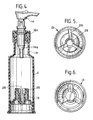
- FIG. 4 illustrates a second embodiment of dispenser of the present invention which again comprises generally tubular container 11, liquid pump dispenser 14, and take-up piston 13.
- the type of liquid pump dispenser is as described with reference to Figures 1 to 3 and as shown in Figure 4 is snap fitted to the outlet end 12 a of the tubular container 11, the container having a reduced diameter neck portion 11 a through which a pump housing 14 a of the pump dispenser projects into the container.
- the degree to which the pump housing 14 a protrudes into the opening 12 will normally affect the degree to which take-up piston 13 can approach the outlet opening of the container 11 in which the pump dispenser 14 is located.
- the take-up piston 13 in the present embodiment has two essential features which allow for the maximum degree of its upward movement within container 11 to provide for maximum dispensing of product therefrom with provision made for the bleeding off of unwanted air pockets within the material to be dispensed.
- a depression 25 is centrally located in the top surface of the take-up piston 13 to accommodate the lower portion of the housing 14 a of the pump 14 as the piston 13 reaches the uppermost portions of its travel. This allows the piston 13 to approach as close as possible to the top of the container 11 thereby reducing the space in which liquid product is held to the absolute minimum practical extent.
- transverse slot means 26 extend downwardly from the top surface of piston 13 and extend from the depression 25 to the side of the immediately adjacent the inner wall surface of the container 11. These slots allow for bleeding off of any entrapped air in the product to be dispensed since they allow for the entrapped air to migrate to the interface between the sides of the piston 13 and the inner wall surface of the container 11.
- the tolerances in sealing fit between piston 13 and wall surfaces are close enough to prevent liquid product from leaking past the piston 13 but not so close to preclude unwanted air from being vented past those surfaces out of the chamber defined by the walls of container 11, piston 13 and pump housing 14 a holding the product.
Landscapes
- Closures For Containers (AREA)
- Containers And Packaging Bodies Having A Special Means To Remove Contents (AREA)
- Reciprocating Pumps (AREA)
Abstract
Description
- The present invention is a pump dispenser for viscous fluids, namely creams, lotions, and the like.
- The Prior art shows a variety of dispensers for fluid masses which comprise a generally tubular container with a pumping mechanism at one end and a take-up piston at the other. In such dispensers, the pumping mechanism is adapted to dispense the product from the container. As products is removed from the container which holds it, the take-up piston is moved by atmospheric pressure towards the pumping mechanism to insure that the fluid product and any associated reservoir in the pumping mechanism do not develop unwanted voids or open spaces which would interfere with the desired dispensing action on subsequent uses of the dispenser. One approach to the design of an appropriate pumping mechanism for one end of such containers is to provide a container body part which is resiliently compressible to effect a decrease in volume of a pumping chamber so as to cause the dispensing of product from the container. Examples of devices which use such an approach are US Patent Nos. 3,088,636; 3,361,305; 3,768,705; 4,154,371; 4,402,431; 4,413,759; 4,442,958; 4,474,313; and 4,533,069.
- An alternative approach to the design of an appropriate pumping mechanism for tubular containers having a take-up piston at its opposite end is to provide a pumping dispenser having movable, rigid members which effect an appropriate volume reduction in a reservoir to dispense product therefrom. The following patents have been noted as following this approach:
- US Patent No. 4,301,948 to J Czech illustrates a pumping mechanism which comprises a head member in the form of a substantially cylindrical cap which is slidely supported on an outer side wall surface of the container. Movement of the head member towards the tubular container effects a reduction in a pump chamber containing the product to effect dispensing of the product through a suitable outlet in the head member.
- US Patent No. 4,323,175 to J Eckert illustrates a dispenser having a delivery device on the upper side of a supply container, transverse to the main direction in which the supply cosntainer extends. This delivery device has a cylinder space in which is arranged a displacement piston which is adapted to be displaced axially.
- US Patent No. 4,485,943 to J Czech shows a dispenser which utilises a spring-biased piston to effect an appropriate reduction in the volume of a pump chamber. The path of egress of the material from the pump chamber to the outlet first lies in a direction lateral to the path of travel of the piston and thence parallel to the path of travel of the piston but laterally displaced therefrom.
- US Patent 4,511,068 to J Bossina and 4,598,843 to D D Foster et al both show the use of spring-mounted pistons to effect removal of viscous product from the type of tubular container described before. In both cases the products is dispensed through outlet means in the piston structure initially in the direction that is parallel, and coaxial, with the path of travel of the piston, and the lateral dimensions of the piston are substantially the same as the inner diameter of the tubular container. In other words, the lower surface of the delivery piston at its circumferential portions makes sealing contact with the inner walls of the tubular container.
- The present invention is a viscous product dispenser which comprises: a generally tubular container body to hold the product; a take-up piston at the lower end of the body which responds to discharging of product from the container body by shifting its position towards the upper end of the body so as to decrease the internal volume of the container body holding the product by an amount corresponding to the volume of product discharged; and a bulk liquid pump dispenser at the upper portion of the container body which comprises an inlet for product extending into the container body portion, intended to hold the product and a finger-depressible, spring-biased piston/cylinder pumping mechanism located within. The liquid pump dispenser has a product outlet conduit which is parallel to the axis defining the inlet for product from the container into the pump dispenser. The product outlet conduit within the pump dispenser is substantially coaxial with the centre of the piston in the pumping mechanism. The piston in the pumping mechanism, which is movable towards and away from a reservoir within the cylinder encasing it, is substantially smaller in width than the internal width of the tubular container.
- In a preferred embodiment of the dispenser modifications have been made to the take-up piston to insure that the piston can advance, to the maximum extent possible, upwardly inside the tubular container body to dispense product therefrom while providing means to vent any undesired, entrapped air within the product holding sections of the container to ensure continued functioning of the dispenser. These objects are achieved by having the upper surface of the piston provided with a centrally located depression to accommodate the lower sections of the pump housing and with transverse slot means, to achieve the desired bleeding off of any entrapped air, leading outwardly from the depression to those portions of the piston surface immediately adjacent the inner side walls of the container.
- The present invention is further understood by reference to the Drawings which illustrate the present invention wherein:
- FIG. 1 is an exploded view, in perspective, showing the three major elements of a first embodiment of the pumping mechanism;
- FIG. 2 is a view in partial cross-section showing the parts of Figure 1 as assembled container;
- FIG. 3 is a cross-section view in greater detail of the bulk liquid pump dispenser;
- FIG. 4 is a cross-sectional, side view of a second embodiment of a dispenser;
- FIG. 5 is a plan view from above of the take-up piston of Figure 4; and
- FIG. 6 is a plan view from below of the take-up piston of Figure 4.
- FIG. 1 illustrates, in perspective, the three major elements of the container of the present invention. These elements are novel, in combination, although the individual elements themselves are conventional. The first element is a tubular container 11 having a suitable outlet opening 12 at its upper end. This tubular container, at its opposed open end, is adapted to receive a take-
up piston 13 which, under the influence of atmospheric pressure, is urged in an upward direction towards the outlet as product is pumped from the inside of the container 11. The combination of tubular container 11 and take-up piston 13 is broadly known as indicated by the various US patents referenced hereinbefore. Further details regarding this combination can be found therein. - The point of novelty for the present container relates to the use of a bulk
liquid pump dispenser 14 rather than the various types of pumping mechanisms illustrated in the aforementioned US patents. This bulk liquid pump dispenser is also a conventional item but has not been used in connection with the combination of a tubular container 11 and a take-up piston 13 as described and claimed herein. Commonly, the bulkliquid pump dispenser 14 used in connection with the present invention is utilised with containers that have a fixed bottom. Suitable liquid pump dispensers of this type are readily available from a number of commercial sources including Calmar Inc of Watchung, New Jersey. - FIG. 3 illustrates this type of
pump dispenser 14 in cross-section in more detail. The pump comprises aneductor head 15, adispenser piston 16, an optional locking ring 17, acaplet 18 andcontainer cap 19, apiston seal 20, aresponsor spring 21 andaccumulator cylinder 22, and aspherical valve 23. The manner in which the pump dispenser shown in FIG. 3 is used is well known. Briefly stated, when a finger is used to depresseductor head 15, thedispenser piston 16 moves downwardly also movingpiston seal 20 downwardly to wipe the interior surfaces ofaccumulator cylinder 22. This forces product up through an internal bore (not shown) withindispenser piston 16 and out through the communicating outlet bore in thehead 15. Checkball valve 23 seals theinlet 24, leading to the container as this occurs preventing the flow of product fromcylinder 22 into the container 11. Release ofhead 15 allowsspring 21 to urge thepiston 16 back up inside theaccumulator cylinder 22 to its original rest position while also allowing for the unseating ofcheck ball valve 23 allowing more product to flow intoaccumulator cylinder 22 from the container 11. As this is occurring, thefollower piston 13 moves upwardly to avoid the formation of air voids within the container 11. - In designing the above system, it is preferable to insure that the lower end of the dispenser pump shown in FIG. 3 is substantially on the same level as the upper cap portion of the container 11 so that, when the
follower piston 13 arrives at its uppermost position in the container 11, as little product as possible remains undispensed from the container. This is possible because a dip tube (or inductor) is not present at the lower product inlet end of the pump dispenser shown in FIG. 3, although such a component is commonly present in bulk liquid pump dispensers of this type utilised with conventional, fixed bottom product containers. - The apparatus of the present invention has certain advantages over conventional dispensers which combine the bulk liquid pump dispenser used herein with a standard bottle not containing a take-up piston. Such conventional lotion pump/bottle dispensers cease to function if heavy viscosity products such as cold cream, petroleum jelly, and the like are contained in the bottle due to cavitation around the dip tube. The present invention solves that problem by the provision of the take-up piston in the dispenser. In regard to the type of dispensers shown in US Patent Nos. 4,511,068 and 4,598,843, the present dispensing system has differing advantages. For example, the present dispenser can be used in an upright, table top position whereas the type of dispensers shown in the two aforementioned patents need to be held and tilted in the hand in order to dispense the product due to the angle of the outlet opening in such dispensers. The present dispenser is a more closed system due to the design of the bulk liquid pump (ie the fact that the spring positively is biased against the sealed dispenser piston when the pump is not being used) so that product bearding at elevated temperatures is substantially reduced as compared to the type of dispenser shown in the two aforementioned patents.
- FIG. 4 illustrates a second embodiment of dispenser of the present invention which again comprises generally tubular container 11,
liquid pump dispenser 14, and take-up piston 13. The type of liquid pump dispenser is as described with reference to Figures 1 to 3 and as shown in Figure 4 is snap fitted to theoutlet end 12 a of the tubular container 11, the container having a reduced diameter neck portion 11 a through which a pump housing 14 a of the pump dispenser projects into the container. The degree to which the pump housing 14 a protrudes into theopening 12 will normally affect the degree to which take-up piston 13 can approach the outlet opening of the container 11 in which thepump dispenser 14 is located. - The take-
up piston 13 in the present embodiment has two essential features which allow for the maximum degree of its upward movement within container 11 to provide for maximum dispensing of product therefrom with provision made for the bleeding off of unwanted air pockets within the material to be dispensed. Firstly, adepression 25 is centrally located in the top surface of the take-up piston 13 to accommodate the lower portion of thehousing 14 a of thepump 14 as thepiston 13 reaches the uppermost portions of its travel. This allows thepiston 13 to approach as close as possible to the top of the container 11 thereby reducing the space in which liquid product is held to the absolute minimum practical extent. Secondly transverse slot means 26 (for example, three slots at 120° to one another) extend downwardly from the top surface ofpiston 13 and extend from thedepression 25 to the side of the immediately adjacent the inner wall surface of the container 11. These slots allow for bleeding off of any entrapped air in the product to be dispensed since they allow for the entrapped air to migrate to the interface between the sides of thepiston 13 and the inner wall surface of the container 11. The tolerances in sealing fit betweenpiston 13 and wall surfaces are close enough to prevent liquid product from leaking past thepiston 13 but not so close to preclude unwanted air from being vented past those surfaces out of the chamber defined by the walls of container 11,piston 13 and pumphousing 14 a holding the product. - The foregoing is presented for illustrative purposes only and should not, therefore, be construed in a limiting sense. The scope of protection that is sought is set forth in the claims which follow.
Claims (7)
Priority Applications (1)
| Application Number | Priority Date | Filing Date | Title |
|---|---|---|---|
| AT88300637T ATE71908T1 (en) | 1987-01-28 | 1988-01-26 | DISPENSER FOR VISCOSE LIQUIDS. |
Applications Claiming Priority (4)
| Application Number | Priority Date | Filing Date | Title |
|---|---|---|---|
| US802487A | 1987-01-28 | 1987-01-28 | |
| US8024 | 1987-01-28 | ||
| US77913 | 1987-07-27 | ||
| US07/077,913 US4854484A (en) | 1987-01-28 | 1987-07-27 | Viscous product dispenser |
Publications (3)
| Publication Number | Publication Date |
|---|---|
| EP0276983A2 true EP0276983A2 (en) | 1988-08-03 |
| EP0276983A3 EP0276983A3 (en) | 1988-10-19 |
| EP0276983B1 EP0276983B1 (en) | 1992-01-22 |
Family
ID=26677658
Family Applications (1)
| Application Number | Title | Priority Date | Filing Date |
|---|---|---|---|
| EP19880300637 Expired - Lifetime EP0276983B1 (en) | 1987-01-28 | 1988-01-26 | Pump dispenser for viscous fluids |
Country Status (7)
| Country | Link |
|---|---|
| US (1) | US4854484A (en) |
| EP (1) | EP0276983B1 (en) |
| JP (1) | JPH0667496B2 (en) |
| CA (1) | CA1279618C (en) |
| DE (1) | DE3867854D1 (en) |
| ES (1) | ES2030164T3 (en) |
| GR (1) | GR3004177T3 (en) |
Cited By (4)
| Publication number | Priority date | Publication date | Assignee | Title |
|---|---|---|---|---|
| US4953758A (en) * | 1988-10-24 | 1990-09-04 | Mark-O Industries | Valve construction |
| EP0481854A1 (en) * | 1990-10-17 | 1992-04-22 | Société Anonyme dite:ETABLISSEMENTS VALOIS | Method for the vacuum packaging of liquid or paste products in dispensers, device therefor and dispenser thus obtained |
| EP0531257A1 (en) * | 1991-09-05 | 1993-03-10 | Ciba-Geigy Ag | Method and device for storing and administering peptid containing dispersions |
| US7306124B2 (en) | 2003-07-03 | 2007-12-11 | Masatoshi Masuda | Piston for fluid container |
Families Citing this family (11)
| Publication number | Priority date | Publication date | Assignee | Title |
|---|---|---|---|---|
| US5667104A (en) * | 1992-05-22 | 1997-09-16 | Meshberg; Philip | Directional dispenser and method of its use |
| US5593064A (en) * | 1993-12-09 | 1997-01-14 | Meshberg; Philip | Promotional dispenser and method for its use |
| US5687878A (en) * | 1994-04-15 | 1997-11-18 | Owens-Brockway Plastic Products Inc. | Flexible tube with pump dispenser and method of making |
| US5800770A (en) * | 1994-04-15 | 1998-09-01 | Owens-Brockway Plastic Products Inc. | Method of making a flexible tube |
| US5988443A (en) * | 1994-04-15 | 1999-11-23 | Owens-Brockway Plastic Products Inc. | Flexible tube with pump dispenser and method of making |
| EP1033318B1 (en) * | 1999-02-18 | 2002-09-18 | FOBOHA GmbH | Tube shoulder and process for its manufacture |
| US20080145135A1 (en) * | 2006-12-13 | 2008-06-19 | Jason Scanlon | Petroleum-based composition dispenser |
| TWI483780B (en) * | 2008-09-11 | 2015-05-11 | Gojo Ind Inc | Pump having a flexible mechanism for engagement with a dispenser |
| TW201202102A (en) * | 2010-07-01 | 2012-01-16 | guo-zhong Fang | Pushing material-gathering type storage container |
| EP2998030A1 (en) * | 2014-09-17 | 2016-03-23 | Sulzer Mixpac AG | Piston for a cartridge, cartridge and method of venting a cartridge |
| DE102015207469B4 (en) * | 2015-04-23 | 2023-04-20 | Skf Lubrication Systems Germany Gmbh | Supply device for viscous media |
Citations (5)
| Publication number | Priority date | Publication date | Assignee | Title |
|---|---|---|---|---|
| US4045938A (en) * | 1976-03-26 | 1977-09-06 | Barrier Pressure Container, Inc. | Method of filling barrier pressure container |
| US4154371A (en) * | 1976-03-19 | 1979-05-15 | Henkel Kommanditgesellschaft Auf Aktien | Dispensing container |
| JPS58122066A (en) * | 1982-01-18 | 1983-07-20 | Canyon Corp | Dispenser |
| US4511068A (en) * | 1982-01-19 | 1985-04-16 | Gap Gesselschaft Fuer Auswertungen Und Patente Ag | Dispenser for paste-like products |
| EP0143183B1 (en) * | 1983-10-28 | 1988-06-08 | Ing. Erich Pfeiffer GmbH & Co. KG | Dispenser for active materials |
Family Cites Families (9)
| Publication number | Priority date | Publication date | Assignee | Title |
|---|---|---|---|---|
| US3288334A (en) * | 1965-05-28 | 1966-11-29 | Calmar Inc | Disppenser with collapsible container and pump |
| US3420413A (en) * | 1967-08-14 | 1969-01-07 | Diamond Int Corp | Liquid and paste dispenser |
| US4134523A (en) * | 1977-05-09 | 1979-01-16 | Southern Can Company | Vented piston for barrier pressure containers |
| JPS5538783U (en) * | 1978-09-07 | 1980-03-12 | ||
| DE3035705A1 (en) * | 1980-09-22 | 1982-05-06 | Henkel KGaA, 4000 Düsseldorf | DONOR |
| IT1134954B (en) * | 1981-01-07 | 1986-08-20 | Sar Spa | MANUALLY OPERATED PUMP FOR DISPENSING UNDER PRESSURE OF LIQUID AND / OR DENSE SUBSTANCES CONTAINED IN A CONTAINER ON WHICH THE PUMP IS MOUNTED |
| US4485943A (en) * | 1982-03-08 | 1984-12-04 | Joachim Czech | Dispenser for liquids or pasty products |
| JPS59153874U (en) * | 1983-03-30 | 1984-10-16 | 株式会社吉野工業所 | Creamy storage container |
| JPH0412931Y2 (en) * | 1985-10-15 | 1992-03-26 |
-
1987
- 1987-07-27 US US07/077,913 patent/US4854484A/en not_active Expired - Fee Related
-
1988
- 1988-01-21 CA CA000557056A patent/CA1279618C/en not_active Expired - Fee Related
- 1988-01-26 DE DE8888300637T patent/DE3867854D1/en not_active Expired - Fee Related
- 1988-01-26 ES ES198888300637T patent/ES2030164T3/en not_active Expired - Lifetime
- 1988-01-26 EP EP19880300637 patent/EP0276983B1/en not_active Expired - Lifetime
- 1988-01-27 JP JP63016788A patent/JPH0667496B2/en not_active Expired - Lifetime
-
1992
- 1992-03-27 GR GR920400546T patent/GR3004177T3/el unknown
Patent Citations (5)
| Publication number | Priority date | Publication date | Assignee | Title |
|---|---|---|---|---|
| US4154371A (en) * | 1976-03-19 | 1979-05-15 | Henkel Kommanditgesellschaft Auf Aktien | Dispensing container |
| US4045938A (en) * | 1976-03-26 | 1977-09-06 | Barrier Pressure Container, Inc. | Method of filling barrier pressure container |
| JPS58122066A (en) * | 1982-01-18 | 1983-07-20 | Canyon Corp | Dispenser |
| US4511068A (en) * | 1982-01-19 | 1985-04-16 | Gap Gesselschaft Fuer Auswertungen Und Patente Ag | Dispenser for paste-like products |
| EP0143183B1 (en) * | 1983-10-28 | 1988-06-08 | Ing. Erich Pfeiffer GmbH & Co. KG | Dispenser for active materials |
Non-Patent Citations (1)
| Title |
|---|
| PATENT ABSTRACTS OF JAPAN, vol. 7, no. 232 (C-190)[1377], 14th October 1983; & JP-A-58 122 066 (KIYANIYON K.K.) 20-07-1983 * |
Cited By (7)
| Publication number | Priority date | Publication date | Assignee | Title |
|---|---|---|---|---|
| US4953758A (en) * | 1988-10-24 | 1990-09-04 | Mark-O Industries | Valve construction |
| EP0481854A1 (en) * | 1990-10-17 | 1992-04-22 | Société Anonyme dite:ETABLISSEMENTS VALOIS | Method for the vacuum packaging of liquid or paste products in dispensers, device therefor and dispenser thus obtained |
| FR2668118A1 (en) * | 1990-10-17 | 1992-04-24 | Valois | PROCESS FOR PACKAGING PASTY LIQUID PRODUCTS IN VACUUM DISPENSER, DEVICE FOR IMPLEMENTING THE SAME, AND DISPENSERS THUS OBTAINED |
| US5217050A (en) * | 1990-10-17 | 1993-06-08 | Valois | Method of vacuum packaging paste or liquid products in a dispenser, device for implementing this method |
| EP0531257A1 (en) * | 1991-09-05 | 1993-03-10 | Ciba-Geigy Ag | Method and device for storing and administering peptid containing dispersions |
| US7306124B2 (en) | 2003-07-03 | 2007-12-11 | Masatoshi Masuda | Piston for fluid container |
| US7306123B2 (en) * | 2003-07-03 | 2007-12-11 | Masatoshi Masuda | Fluid discharge pump and fluid container |
Also Published As
| Publication number | Publication date |
|---|---|
| JPH0667496B2 (en) | 1994-08-31 |
| GR3004177T3 (en) | 1993-03-31 |
| EP0276983A3 (en) | 1988-10-19 |
| ES2030164T3 (en) | 1992-10-16 |
| EP0276983B1 (en) | 1992-01-22 |
| DE3867854D1 (en) | 1992-03-05 |
| JPS63200857A (en) | 1988-08-19 |
| CA1279618C (en) | 1991-01-29 |
| US4854484A (en) | 1989-08-08 |
Similar Documents
| Publication | Publication Date | Title |
|---|---|---|
| US4809878A (en) | Pump dispenser for viscous fluids | |
| CA1279618C (en) | Pump dispenser for viscous fluids | |
| US4964544A (en) | Push up dispenser with capsule valve | |
| KR100228660B1 (en) | Piston dispensing apparatus | |
| US4958754A (en) | Dispenser or sprayer with vent system | |
| EP2599558B1 (en) | Airless pump system | |
| NL1028921C2 (en) | Dispensing device. | |
| KR960007219B1 (en) | Dispensing apparatus for pressurized dispensing containers | |
| JP6889214B2 (en) | Dispenser with fluid reservoir containing split or porous material | |
| KR0172622B1 (en) | A pressure dispensing pump | |
| JP2004538139A (en) | Mechanical pressure type dispenser | |
| JPH07206057A (en) | Refillable straying contianer and replenishing device, and method to replenish straying container | |
| US5058780A (en) | Dosing system for an unvented container | |
| JP2016529169A5 (en) | ||
| EP3431187B1 (en) | Device for dispensing a plurality of fluid products | |
| US20230415973A1 (en) | An aerosol metering valve system and a container comprising an aerosol metering valve system | |
| AU2015218380B2 (en) | Dispensing valve incorporating a metering valve | |
| US6102255A (en) | Invertible dispensing means for spray containers | |
| EP3965948B1 (en) | Dispensing device | |
| EP1405676A1 (en) | Spraying device | |
| EP2117396A2 (en) | Dispenser |
Legal Events
| Date | Code | Title | Description |
|---|---|---|---|
| PUAI | Public reference made under article 153(3) epc to a published international application that has entered the european phase |
Free format text: ORIGINAL CODE: 0009012 |
|
| AK | Designated contracting states |
Kind code of ref document: A2 Designated state(s): AT BE CH DE ES FR GB GR IT LI NL SE |
|
| PUAL | Search report despatched |
Free format text: ORIGINAL CODE: 0009013 |
|
| AK | Designated contracting states |
Kind code of ref document: A3 Designated state(s): AT BE CH DE ES FR GB GR IT LI NL SE |
|
| 17P | Request for examination filed |
Effective date: 19881011 |
|
| 17Q | First examination report despatched |
Effective date: 19900709 |
|
| GRAA | (expected) grant |
Free format text: ORIGINAL CODE: 0009210 |
|
| AK | Designated contracting states |
Kind code of ref document: B1 Designated state(s): AT BE CH DE ES FR GB GR IT LI NL SE |
|
| REF | Corresponds to: |
Ref document number: 71908 Country of ref document: AT Date of ref document: 19920215 Kind code of ref document: T |
|
| REF | Corresponds to: |
Ref document number: 3867854 Country of ref document: DE Date of ref document: 19920305 |
|
| ITF | It: translation for a ep patent filed | ||
| ET | Fr: translation filed | ||
| REG | Reference to a national code |
Ref country code: ES Ref legal event code: FG2A Ref document number: 2030164 Country of ref document: ES Kind code of ref document: T3 |
|
| PLBE | No opposition filed within time limit |
Free format text: ORIGINAL CODE: 0009261 |
|
| STAA | Information on the status of an ep patent application or granted ep patent |
Free format text: STATUS: NO OPPOSITION FILED WITHIN TIME LIMIT |
|
| RAP4 | Party data changed (patent owner data changed or rights of a patent transferred) |
Owner name: UNILEVER N.V. Owner name: UNILEVER PLC |
|
| REG | Reference to a national code |
Ref country code: GR Ref legal event code: FG4A Free format text: 3004177 |
|
| 26N | No opposition filed | ||
| EAL | Se: european patent in force in sweden |
Ref document number: 88300637.1 |
|
| PGFP | Annual fee paid to national office [announced via postgrant information from national office to epo] |
Ref country code: FR Payment date: 19971208 Year of fee payment: 11 |
|
| PGFP | Annual fee paid to national office [announced via postgrant information from national office to epo] |
Ref country code: AT Payment date: 19971211 Year of fee payment: 11 |
|
| PGFP | Annual fee paid to national office [announced via postgrant information from national office to epo] |
Ref country code: SE Payment date: 19971215 Year of fee payment: 11 |
|
| PGFP | Annual fee paid to national office [announced via postgrant information from national office to epo] |
Ref country code: GR Payment date: 19971216 Year of fee payment: 11 |
|
| PGFP | Annual fee paid to national office [announced via postgrant information from national office to epo] |
Ref country code: GB Payment date: 19971219 Year of fee payment: 11 |
|
| PGFP | Annual fee paid to national office [announced via postgrant information from national office to epo] |
Ref country code: DE Payment date: 19971222 Year of fee payment: 11 |
|
| PGFP | Annual fee paid to national office [announced via postgrant information from national office to epo] |
Ref country code: CH Payment date: 19980106 Year of fee payment: 11 |
|
| PGFP | Annual fee paid to national office [announced via postgrant information from national office to epo] |
Ref country code: BE Payment date: 19980108 Year of fee payment: 11 |
|
| PGFP | Annual fee paid to national office [announced via postgrant information from national office to epo] |
Ref country code: NL Payment date: 19980121 Year of fee payment: 11 |
|
| PG25 | Lapsed in a contracting state [announced via postgrant information from national office to epo] |
Ref country code: GB Free format text: LAPSE BECAUSE OF NON-PAYMENT OF DUE FEES Effective date: 19990126 Ref country code: AT Free format text: LAPSE BECAUSE OF NON-PAYMENT OF DUE FEES Effective date: 19990126 |
|
| PG25 | Lapsed in a contracting state [announced via postgrant information from national office to epo] |
Ref country code: SE Free format text: LAPSE BECAUSE OF NON-PAYMENT OF DUE FEES Effective date: 19990127 |
|
| PG25 | Lapsed in a contracting state [announced via postgrant information from national office to epo] |
Ref country code: LI Free format text: LAPSE BECAUSE OF NON-PAYMENT OF DUE FEES Effective date: 19990131 Ref country code: GR Free format text: LAPSE BECAUSE OF NON-PAYMENT OF DUE FEES Effective date: 19990131 Ref country code: CH Free format text: LAPSE BECAUSE OF NON-PAYMENT OF DUE FEES Effective date: 19990131 Ref country code: BE Free format text: LAPSE BECAUSE OF NON-PAYMENT OF DUE FEES Effective date: 19990131 |
|
| BERE | Be: lapsed |
Owner name: UNILEVER N.V. Effective date: 19990131 |
|
| PG25 | Lapsed in a contracting state [announced via postgrant information from national office to epo] |
Ref country code: NL Free format text: LAPSE BECAUSE OF NON-PAYMENT OF DUE FEES Effective date: 19990801 |
|
| GBPC | Gb: european patent ceased through non-payment of renewal fee |
Effective date: 19990126 |
|
| REG | Reference to a national code |
Ref country code: CH Ref legal event code: PL |
|
| PG25 | Lapsed in a contracting state [announced via postgrant information from national office to epo] |
Ref country code: FR Free format text: LAPSE BECAUSE OF NON-PAYMENT OF DUE FEES Effective date: 19990930 |
|
| PG25 | Lapsed in a contracting state [announced via postgrant information from national office to epo] |
Ref country code: DE Free format text: LAPSE BECAUSE OF NON-PAYMENT OF DUE FEES Effective date: 19991103 |
|
| REG | Reference to a national code |
Ref country code: FR Ref legal event code: ST |
|
| PG25 | Lapsed in a contracting state [announced via postgrant information from national office to epo] |
Ref country code: IT Free format text: LAPSE BECAUSE OF NON-PAYMENT OF DUE FEES;WARNING: LAPSES OF ITALIAN PATENTS WITH EFFECTIVE DATE BEFORE 2007 MAY HAVE OCCURRED AT ANY TIME BEFORE 2007. THE CORRECT EFFECTIVE DATE MAY BE DIFFERENT FROM THE ONE RECORDED. Effective date: 20050126 |
|
| PGFP | Annual fee paid to national office [announced via postgrant information from national office to epo] |
Ref country code: ES Payment date: 20050208 Year of fee payment: 18 |
|
| PG25 | Lapsed in a contracting state [announced via postgrant information from national office to epo] |
Ref country code: ES Free format text: LAPSE BECAUSE OF NON-PAYMENT OF DUE FEES Effective date: 20060127 |
|
| REG | Reference to a national code |
Ref country code: ES Ref legal event code: FD2A Effective date: 20060127 |