EP0276193A2 - Internal combustion engine - Google Patents
Internal combustion engine Download PDFInfo
- Publication number
- EP0276193A2 EP0276193A2 EP88730010A EP88730010A EP0276193A2 EP 0276193 A2 EP0276193 A2 EP 0276193A2 EP 88730010 A EP88730010 A EP 88730010A EP 88730010 A EP88730010 A EP 88730010A EP 0276193 A2 EP0276193 A2 EP 0276193A2
- Authority
- EP
- European Patent Office
- Prior art keywords
- fuel
- valve
- chamber
- activation chamber
- compressed air
- Prior art date
- Legal status (The legal status is an assumption and is not a legal conclusion. Google has not performed a legal analysis and makes no representation as to the accuracy of the status listed.)
- Granted
Links
Images


Classifications
-
- F—MECHANICAL ENGINEERING; LIGHTING; HEATING; WEAPONS; BLASTING
- F02—COMBUSTION ENGINES; HOT-GAS OR COMBUSTION-PRODUCT ENGINE PLANTS
- F02B—INTERNAL-COMBUSTION PISTON ENGINES; COMBUSTION ENGINES IN GENERAL
- F02B19/00—Engines characterised by precombustion chambers
- F02B19/02—Engines characterised by precombustion chambers the chamber being periodically isolated from its cylinder
-
- F—MECHANICAL ENGINEERING; LIGHTING; HEATING; WEAPONS; BLASTING
- F02—COMBUSTION ENGINES; HOT-GAS OR COMBUSTION-PRODUCT ENGINE PLANTS
- F02B—INTERNAL-COMBUSTION PISTON ENGINES; COMBUSTION ENGINES IN GENERAL
- F02B1/00—Engines characterised by fuel-air mixture compression
- F02B1/02—Engines characterised by fuel-air mixture compression with positive ignition
- F02B1/04—Engines characterised by fuel-air mixture compression with positive ignition with fuel-air mixture admission into cylinder
-
- F—MECHANICAL ENGINEERING; LIGHTING; HEATING; WEAPONS; BLASTING
- F02—COMBUSTION ENGINES; HOT-GAS OR COMBUSTION-PRODUCT ENGINE PLANTS
- F02B—INTERNAL-COMBUSTION PISTON ENGINES; COMBUSTION ENGINES IN GENERAL
- F02B75/00—Other engines
- F02B75/12—Other methods of operation
- F02B2075/125—Direct injection in the combustion chamber for spark ignition engines, i.e. not in pre-combustion chamber
-
- Y—GENERAL TAGGING OF NEW TECHNOLOGICAL DEVELOPMENTS; GENERAL TAGGING OF CROSS-SECTIONAL TECHNOLOGIES SPANNING OVER SEVERAL SECTIONS OF THE IPC; TECHNICAL SUBJECTS COVERED BY FORMER USPC CROSS-REFERENCE ART COLLECTIONS [XRACs] AND DIGESTS
- Y02—TECHNOLOGIES OR APPLICATIONS FOR MITIGATION OR ADAPTATION AGAINST CLIMATE CHANGE
- Y02T—CLIMATE CHANGE MITIGATION TECHNOLOGIES RELATED TO TRANSPORTATION
- Y02T10/00—Road transport of goods or passengers
- Y02T10/10—Internal combustion engine [ICE] based vehicles
- Y02T10/12—Improving ICE efficiencies
Landscapes
- Engineering & Computer Science (AREA)
- Chemical & Material Sciences (AREA)
- Combustion & Propulsion (AREA)
- Mechanical Engineering (AREA)
- General Engineering & Computer Science (AREA)
- Combustion Methods Of Internal-Combustion Engines (AREA)
Abstract
Description
- The present invention relates to an internal combustion engine, and more particularly to an internal combustion engine including a fuel activation chamber disposed near a main combustion chamber and a valve disposed between the fuel activation chamber and the main combustion chamber to open and close therebetween.
- An internal combustion engine involves, for example as a combustion system of a compression ignition engine, a direct injection type engine, a precombustion type engine, a swirl chamber type engine and an air chamber type engine. However, in any combustion system, since liquid fuel is directly injected into a combustion chamber, the compression ignition combustion may be started before the injected fuel is uniformly mixed with air. In this case, hydrocarbon in imperfect combustion is produced in the combustion chamber and black smoke is exhausted from the compression ignition engine. Accordingly, the combustion effieciency is reduced and air pollution is effected.
- Further, since most of the current compression ignition engine are adapted to be ignited with a high compression ratio and in a high temperature, much nitrogen oxide (Nox) is exhausted and air pollution is also effected.
- Accordingly, the present inventor has proposed, in view of such circumstances and inconveniences, an internal combustion engine including a fuel activation chamber disposed near a main combustion chamber and a valve disposed between the activation chamber and the main combustion chamber to open and close therebetween (refer to Japanese Patent Application Nos. 61-253194 and 61-277908).
- Since the valve of the above internal combustion engine is structured to be opened and closed by movement of a valve body thereof to the main combustion chamber side from a valve seat thereof, there is no large loss due to the flow of fuel from the activation chamber to the main combustion chamber and accordingly the rotational number and the maximum output power of the internal combustion engine could be improved.
- However, the present inventor further continued research and development and has developed an internal combustion engine having further enhanced combustion efficiency and improved maximum output power.
- It is a first object of the present invention to provide an internal combustion engine having further enhanced combustion efficiency and maximum output power.
- In order to achieve the above object, the present invention provides an internal combustion engine including a fuel activation chamber disposed near a main combustion chamber and a valve disposed between the fuel activation chamber and the main combustion chamber to open and close therebetween, wherein the valve is structured to be opened by movement of a valve body thereof to the fuel activation chamber side.
- Further, in order to achieve the above object, the present invention provides an internal combustion engine including a fuel activation chamber disposed near a main combustion chamber and a valve disposed between the fuel activation chamber and the main combustion chamber to open and close therebetween, wherein the valve is structured to be opened by movement of a valve body thereof to the fuel activation chamber side, and comprising an ignition plug disposed to be exposed in the fuel activation chamber.
- Furthermore, in order to achieve the above object, the present invention provides an internal combustion engine including a fuel activation chamber disposed near a main combustion chamber and a valve disposed between the fuel activation chamber and the main combustion chamber to open and close therebetween, wherein the valve is structured to be opened by movement of a valve body thereof to the fuel activation chamber side, and a fuel feeding hole for feeding fuel to the fuel activation chamber and a compressed air introducing hole for feeding compressed air from the main combustion chamber to the fuel activation chamber are joined each other at respective intermediate positions so that the compressed air in the main combustion chamber and the injected fuel from a fuel injection nozzle are premixed to be injected into the fuel activation chamber.
- In addition, in order to achieve the above object, the present invention provides an internal combustion engine including a fuel activation chamber disposed near a main combustion chamber and a valve disposed between the fuel activation chamber and the main combustion chamber to open and close therebetween, comprising valve control means for opening and closing the valve at an ignition timing in a low speed operation and maintaining the valve open in a medium and high speed operation.
- Moreover, in order to achieve the above object, the present invention provides an internal combustion engine including a fuel activation chamber disposed near a main combustion chamber and a valve disposed between the fuel activation chamber and the main combustion chamber to open and close therebetween, wherein the valve is structured to be opened by movement of a valve body thereof to the fuel activation chamber side, and further comprising valve body adjustment means for shifting the valve body to the radial direction or the axial direction thereof in accordance with an operation condition, a pair of notches formed in the valve body and a valve seat of the valve, respectively, and which are overlapped each other by a proper amount in accordance with the shifted amount of the valve body by the adjustment means, and a compressed air injection hole formed in the valve to inject compressed air in the main combustion chamber into the fuel activation chamber by the overlap of the pair of notches so that the compressed air of an amount in accordance with the operation condition is introduced into the fuel activation chamber through the compressed air injection hole.
- Further, it is a second object of the present invention to provide an internal combustion engine which can be manufactured or assembled easily.
- In order to achieve the above object, the present invention provides an internal combustion engine including a fuel activation chamber disposed near a main combustion chamber and a valve disposed between the fuel activation chamber and the main combustion chamber to open and close therebetween, comprising a valve body adjusting means for shifting the valve body in a radial direction or an axial direction thereof in accordance with an operation condition, a pair of notches formed in the valve body and a valve seat of the valve, respectively, and which are overlapped each other in accordance with a shifted amount of the valve body by the valve body adjusting means, and a compressed air injection hole formed in the valve by the overlap of the pair of notches to inject the compressed air in the main combustion chamber into the fuel activation chamber so that the compressed air of an amount in accordance with the operation condition is introduced into the fuel activation chamber through the compressed air injection hole.
-
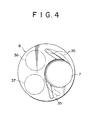
- Figs. 1 to 4 illustrate an embodiment of an internal combustion engine according to the present invention, in which Fig. 1 is a cross-sectional view showing a configuration of the internal combustion engine, Fig. 2 is an enlarged cross-sectional view showing part of the internal combustion engine, Fig. 3 is an enlarged cross-sectional view showing part of the internal combustion engine and Fig. 4 is a plan view showing a configuration of a piston of the internal combustion engine;
- Fig. 5 is a cross-sectional view showing another embodiment of an internal combustion engine according to the present invention; and
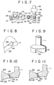
- Figs. 6 to 11 illustrate a further embodiment of an internal combustion engine according to the present invention, in which Fig. 6 is a cross-sectional view showing a configuration of the internal combustion engine, Fig. 7 is a partially cross-sectional enlarged plan view showing part of the internal combustion engine, Fig. 8 is an enlarged perspective view showing part of a valve seat of the internal combustion engine, Fig. 9 is an enlarged perspective view showing part of the internal combustion engine, Fig. 10 is an enlarged cross-section view showing part of the internal combustion engine, and Fig. 11 is an enlarged cross-section view showing part of the internal combustion engine.
- Embodiments of an internal combustion engine according to the present invention will now be described with reference to drawings.
- Figs. 1 to 4 show an embodiment of the present invention.
- An
internal combustion engine 1 of the present embodiment is applied to a combustion ignition engine such as a diesel engine. - The
internal combustion engine 1 comprises afuel activation chamber 3 disposed above and near a main combustion chamber 2. - The
fuel activation chamber 3 is formed in alower portion 4b formed with a relatively large diameter of acylindrical holder 4 having anupper portion 4a formed with a small diameter and astep 4c. - The
activation chamber 3 is in the form of a rotary body having a center formed by a vertical axis of theholder 4 and theupper portion 3a thereof is formed in a conical shape. - The
holder 4 includes a substantially semispherical cavity 5 formed at a bottom thereof with an opening directed downward and which communicates with thefuel activation chamber 3. - The cavity 5 of the
holder 4 is opposed to a substantiallysemispherical cavity 7 formed in an upper portion of apiston 6 with an opening directed upward. - The main combustion chamber 2 is formed into a substantially spherical shape apt to produce a swirl A by the
cavities 5 and 7 when thepiston 6 is at the top dead point for compression. - A communicating
hole 9 extending in the axial direction of theholder 4 is formed in theupper portion 4a of theholder 4. A rod 11 having avalve body 10 at the lower portion thereof is inserted into thehole 9 to seal between theholder 4 and the rod 11. - The
valve body 10 can be fitted in avalve seat 12 formed in theholder 4 between thefuel activation chamber 3 and the cavity 5 and forms avalve 13 together with thevalve seat 12. - A
tappet 14 is fixedly mounted on the upper end of the rod 11 and aspring 15 is disposed between thetappet 14 and acylinder head 8. - The
valve body 10 is always urged to move upward by the resilience of thespring 15 so that the tappet 14 abuts against acam 16. Thus, when thecam 16 is rotated, thevalve body 10 is moved up and down. - The motive power of a crank shaft not shown is transmitted to the
cam 16 through a proper power transmission device to rotate thecam 16 at a predetermined timing. - Accordingly, the
valve 13 is opened and closed in response to the rotation of thecam 16 at a predetermined timing. - It is preferable that the open period of the
valve 13 is set to a proper period between around the end of the compression stroke and around the beginning of the exhaust stroke, while it is not limited thereto. For example, the open period of thevalve 13 may be set to a long period between around the end of the compression stroke and around the end of the induction stroke. - The
valve 13 is preferably constructed so that the open timing thereof precedes in accordance with the rotational speed of the internal combustion engine. A preceding device can be easily structured using a conventional technique and provide in the above-mentioned power transmission device and accordingly detailed description thereof is omitted. - A
fuel feeding hole 18 which feeds injected fuel from afuel injection nozzle 17 into thefuel activation chamber 3 is formed in a side portion of theholder 4. - The
fuel feeding hole 18 is preferably formed eccentrically with respect to the fuel activation chamber 3 (refer to Fig. 2) so that the injected fuel from thefuel injection nozzle 17 forms a clockwise swirl B in Fig. 2. The swirl B facilitates the activation of the fuel. - Further, the
fuel feeding hole 18 and the cavity 5 of theholder 4 communicate with each other through a compressedair introducing hole 18a having a small diameter. The compressedair introducing hole 18a is to introduce the compressed air in the main combustion chamber 2 into thefuel feeding hole 18. The compressed air from the compressedair introducing hole 18a is premixed with the injected fuel from thefuel injection nozzle 17 and the mixture of the compressed air and the injected fuel is injected into thefuel activation chamber 3. - Thus, since the
fuel feeding hole 18 serves to premix the fuel and the compressed air and feed the mixture thereof into thefuel activation chamber 3, thefuel feeding hole 18 forms a so-called premixing port for thefuel activation chamber 3. - Further, an end of a glow plug 19 is slightly protruded in the
fuel activation chamber 3. It is preferable that the glow plug 19 is disposed slightly downstream of thehole 18 in the direction of fuel injection from thehole 18. - An
internal thread 20 is formed in theholder 4 in opposing relationship with thefuel feeding hole 18. Anignition plug 21 is tightly fitted into theinternal thread 20. Anend 21a of theignition plug 21 is disposed within theinternal thread 20 so that the swirl B in thefuel activation chamber 3 is not prevented, while it is a matter of course that theend 21a may be protruded into thechamber 3 from theinternal thread 20. - The
ignition plug 21 is detachably fixed to theinternal thread 20 through ahole 22 formed in thecylinder head 8 corresponding to theinternal thread 20 of theholder 4. - The
holder 4 is further formed with anotherhole 23 and thecylinder head 8 is formed withholes 24 and 25 corresponding to thehole 23 of theholder 4. Thehole 23 is formed so that thehole 23 is directed downstream of the swirl B in thefuel activation chamber 3. The hole 24 communicates with the main combustion chamber 2 through thehole 25. Accordingly, thefuel activation chamber 3 communicates with the main combustion chamber 2 through theholes - An air
quantity adjusting device 26 which is structured to change an aperture volume of thehole 25 with respect to the hole 24 is disposed between theholes 24 and 25. - The air
quantity adjusting device 26 comprises a smallcylindrical rod 27 having an inclined portion 27a formed an end thereof and arotating device 28 which rotates the rod. - The
small rod 27 is configured so that the inclined portion 27a thereof is disposed at an inlet of thehole 25. Therod 27 is rotatably mounted into ahole 29 formed in thecylinder head 8 and coupled with therotating device 28 through a connectingrod 30. - The air
quantity adjusting device 26 is provided to detect a high speed operation, an acceleration operation and/or a heavily loaded operation of the engine and to supplement a quantity of compressed air fed from the main combustion chamber 2 to thefuel activation chamber 3 through the compressedair introducing hole 18a. In adjustment, thesmall rod 27 is angularly moved to adjust the open area formed by overlap of the inclined portion 27a and thehole 25 so that the quantity of compressed air flowing through theholes - The
rotating device 28 rotates thesmall rod 27 by a proper amount on the basis of, for example, a rotational number of a crank shaft not shown, a moved amount of an accelerator pedal, a degree of a variation of the moved amount of the accelerator pedal, a degree of a variation of flow velocity at downstream of a throttle valve in an intake pipe not shown or the like. - The
rotating device 28 may include a processing unit such as a microcomputer for processing detection data obtained by detecting the various variations described above, a stepping motor driven on the basis of the processed result of the processing unit, and a reduction device for the stepping motor. Alternatively, the rotatingdevice 28 may be configured to be mechanically coupled with a throttle valve or an accelerator pedal through connecting means not shown in a link manner. The configuration of therotating device 28 may be determined in consideration of the application and object of the internal combustion engine. - Two
annular grooves 31 are formed in an upper surface 10a of thevalve body 10 and further twoannular grooves 32 are formed in a side periphery 10b of the valve body 10b. The number of thegrooves valve 13 is operated, carbon attached to the upper surface 10a of thevalve body 10 and/or aceiling surface 3a of thefuel activation chamber 3 is removed effectively and carbon attached to the side periphery 10b of thevalve body 10 and/or thevalve seat 12 is also removed effectively. Particularly, since carbon between the upper surface 10a of thevalve body 10 and theceiling surface 3a can be removed, a seal between thevalve body 10 and thecylinder head 8 can be always maintained to a good state when thevalve body 10 is moved up. - The
holder 4 includes thestep 4c formed between theupper portion 4a and thelower portion 4b as described above. Thecylinder head 8 is formed with ahole 8a having a small diameter and ahole 8b having a large diameter in corresponding relationship with the shape of theholder 4 and anannular step 8c is formed between theholes - In the embodiment, a part of the
hole 8b is overlapped on acylinder liner 34 which is fixed to an inner periphery of acylinder block 33 and thehole 8b is formed much eccentrically to the main combustion chamber 2. - The
holder 4 is mounted in thecylinder head 8 as follows. - The
holder 4 is forcedly inserted into theholes cylinder head 8 from the lower part thereof and is integrally fixed to thecylinder head 8. At this time, thestep 4c of theholder 4 is brought into close contact with thestep 8c of thecylinder head 8. Then, the cylinder head is fixed to thecylinder block 33. Theholder 4 is completely fixed by restricting its movement in the vertical direction by thestep 8c of thecylinder head 8 pressing thestep 4c and anupper end surface 34a of theliner 34 pressing part of a bottom 4d of theholder 4. - Further, it is preferable that the
holder 4 is fixed to thecylinder head 8 and is not rotated with respect to thecylinder head 8 by a key, not shown, which is formed at any position to prevent theholder 4 from rotating, while in the case where theholder 4 is formed in a nonrotatable body with respect to an axis thereof, the key is not necessary since theholder 4 is not rotated with respect to thecylinder head 8. - Further, it is a matter of course that a part of the bottom 4d of the
holder 4 extends over theliner 34 greatly to reach thecylinder block 33 so that theholder 4 is fixed. - In the embodiment, the
piston 6 is formed with twoguide grooves 35 extending from thecavity 7 of thepiston 6 straight or curvedly. The number of theguide grooves 35 is not limited thereto. Thegrooves 35 are provided to form a swirl of air in the main combustion chamber 2 effectively in the compression stroke. Accordingly, when theguide grooves 35 are formed in a curvature, it is preferable that the curved line of thegrooves 35 is identical with the direction of the swirl. In Fig. 4, circles 36 and 37 in thepiston 6 shown by one-dot chain line indicate positions of an intake valve and an exhaust valve not shown provided in thecylinder head 8 with respect to thepiston 6. - Operation of the embodiment is now made.
- Assuming that the
internal combustion engine 1 is in the compression stroke, air in the main combustion chamber 2 is compressed. The compressed air in the main combustion chamber 2 is injected into thefuel feeding hole 18 through the compressedair introducing hole 18a and is further guided in thefuel activation chamber 3 from thefuel feeding hole 18. At this time, fuel is injected into thefuel feeding hole 18 from thefuel injection nozzle 17. The injected fuel is premixed with the compressed air in thefuel feeding hole 18 fed from the main combustion chamber 2 through the compressedair introducing hole 18a and the mixture thereof is injected into thefuel activation chamber 3. The swirl B of the fuel-and-air mixture is formed in thefuel activation chamber 3 by the injection thereof and the mixture is heated by the glow plug 19 to facilitate the activation of the mixture so that the mixture is formed uniformly. - Then, near the top dead point for the compression, the
valve body 10 is moved up and thevalve 13 is opened by the rotation of thecam 16 and the resilience of thespring 15. In connection with this operation, theignition plug 21 produces a spark at a predetermined ignition timing. The mixture in thefuel activation chamber 3 is mixed with the compressed air in the main combustion chamber 2 by the opening of thevalve 13 and begins to be ignited and burned. Further, the mixture is exactly ignited by the spark of the ignition plug 19. The mixture in thefuel activation chamber 3 begins to be burned and the pressure thereof in thechamber 3 is suddenly enhanced, so that the mixture is injected through the space between thevalve body 10 and thevalve seat 12 and theholes hole 18a forms a strong swirl in the main combustion chamber 2. The mixture in the main combustion chamber 2 is smoothly burned by this swirl. - As described above, when the
valve 13 is opened and the mixture begins to be burned, thevalve body 10 abuts against theceiling surface 3a to seal between the valve body and thecylinder head 8. The seal prevents the mixture in thefuel activation chamber 3 from leaking out from the gap between theholder 4 and thevalve body 10 to the outside. - Thereafter, the
valve 13 is closed at a proper time, for example, near the end of the expansion stroke or near the end of the exhaust stroke. The same operation as described above is then repeated. - The
internal combustion engine 1 in the embodiment may further comprise, in place of theair adjusting device 26 or together with this device, a compressedair feeding device 38 which feeds the compressed air into thefuel combustion chamber 3 upon acceleration of the internal combustion engine. - The compressed
air feeding device 38 can be composed of, for example as shown in Fig. 1, apump 39 which compresses part of fresh air obtained through an air cleaner, a tank 40 which stores air compressed by the pump, aconduit 41 which guides the compressed air from the tank to thefuel activation chamber 3, a normally closedelectromagnetic valve 42 disposed in theconduit 41, and acontroller 43 which controls to open and close theelectromagnetic valve 42. - The
pump 39 is driven by the motive power of a crank shaft not shown. - The
controller 43 detects the acceleration state or the loaded state of the internal combustion engine to open theelectromagnetic valve 42 so that the compressed air is fed to thefuel activation chamber 3. - In the embodiment, large movement in one direction of a
control rack 44a of afuel feeding pump 44 in the acceleration state or the loaded state of the engine is utilized to press an actuator of aswitch 45 by the movement of thecontrol rack 44a and open the switch, whereby an operating current flows from abattery 46 through theswitch 45 to theelectromagnetic valve 42. -
Reference numeral 47 denotes a check valve disposed in theconduit 48 so that the compressed air does not flow reversely from the tank 40 to thepump - When the compressed
air feeding device 38 is provided, the compressed air may be directly fed to thefuel activation chamber 3 as shown in Fig. 1, while the compressed air may be fed to be injected in the same direction as that of the swirl B and in the tangential direction of the swirl B in thefuel activation chamber 3, that is, the compressed air may be fed, for example, from thehole 23 or thefuel feeding hole 18 or from any position between thehole 23 and thefuel feeding hole 18. - The characteristic operation and effect of the internal combustion engine according to the present invention are summarized as follows.
- The fuel is relatively early injected from the
fuel injection nozzle 17 into thefuel activation chamber 3 having remaining gas of a high temperature contained therein and a wall surface heated to a high temperature and is premixed with the compressed air injected from the compressedair introducing hole 18a. Further, the injected and premixed fuel forms the swirl in thefuel activation chamber 3 and forcedly preheated by the remaining gas, the high-temperature wall surface, the glow plug 19 and the like so that uniform mixture is formed. In this connection, when the compressedair introducing hole 18a is too large, the fuel is self-ignited in thefuel activation chamber 3 in the same manner as the so-called diesel combustion and accordingly the diameter of the compressedair introducing hole 18a is preferably set to a relatively small value. - The uniformly activated (premixed and preheated) mixture existing between the
valve body 10 and theceiling surface 3a of thefuel activation chamber 3 is subjected to the squish operation between the upper surface 10a of thevalve body 10 and theceiling surface 3a of thefuel activation chamber 3, when thevalve body 10 is moved up, to be injected strongly from the openedvalve 13 into the main combustion chamber 2 and is brought into contact with fresh air in the main combustion chamber to be immediately ignited and burned. In this manner, since the internal combustion engine of the present invention effects the ignition and combustion by opening of thevalve 13 without the spark ignition of theignition plug 21 essentially, theignition plug 21 may be removed. Further, utilization of theignition plug 21 can exactly ignite fuel which is hard to be activated and ignited at a predetermined timing. Accordingly, utilization of theignition plug 21 may be determined in consideration of the kind and property of fuel and application of the internal combustion engine. - As apparent from the foregoing, the internal combustion engine of the present invention can select and change the open and close timing of the
valve 13 and/or the spark time of theignition plug 21 so that the ignition timing can be controlled in optimum. When a spark of theignition plug 21 is used to ignite the mixture, the timing of producing the spark from theplug 21 may be synchronized with the opening timing of thevalve 13. - Further, since the open and close timing of the
valve 10 can be controlled, the feeding time of fuel can be also controlled and the fuel and air are premixed and preheated sufficiently to be activated in thefuel activation chamber 3. Accordingly, various gases can be gasified to optimum states suitable for various internal combustion engines. - Thus, various fuel can be employed and the present invention can be applied to the whole internal combustion engine (not limited to the diesel engine and including the general petrol engine).
- The fuel is previously activated in the
fuel activation chamber 3 before ignition and accordingly there is no diesel knocking particular to the diesel combustion. A quiet premix combustion can be achieved with less exhaust gas and particularly black smoke is not almost produced. Accordingly, since the engine can be operated at a high speed rotation and the compression ratio thereof can be reduced slightly, the weight of the engine can be reduced. Further, the excess coefficient can approach 1.0 and accordingly the output power of the engine can be improved. - In the present invention, the
holder 4 may disposed at the middle with respect to thepiston 6. - The shape of the
cavity 7 of thepiston 6 is not limited to a substantially semispherical shape and may be any shape such as a substantially cylindrical shape. - Furthermore, any one or ones of the
grooves valve body 10, the airquantity adjusting device 26, thegroove 35 of thepiston 6 and the compressedair feeding device 38 may be removed and may be provided selectively in consideration of application of theinternal combustion engine 1. - In addition, since the wall surface of the
fuel activation chamber 3 or the whole of theholder 4 is formed of ceramic material, it is preferable that the thermal efficiency of the internal combustion engine can be improved. It is a matter of course that the whole of the engine may be formed of ceramic material together with thecylinder block 8 and thecylinder block 33. - In the embodiment, while it is configured that the main combustion chamber 2 communicates with the halfway position of the
fuel feeding hole 18 through the compressedair introducing hole 18a, the present invention is not limited thereto and it may be configured that the halfway positions of the respective holes are joined with each other. - Fig. 5 shows another embodiment of the present invention. The like elements having the same function as that of the elements of Figs. 1 to 4 are designated by like reference numerals and description thereof is omitted.
- An
internal combustion engine 50 of the embodiment shown in Fig. 5 comprises the substantially same configuration as that of theengine 1 of the embodiment shown in Fig. 1 except that there is provided avalve control device 51 which opens and closes thevalve 13 at an ignition timing in a low speed operation and maintains thevalve 13 open at a medium and high speed operation. Description with respect to the same configuration as that of theengine 1 quotes the description of the embodiment of Figs. 1 to 4, and only thevalve control device 51 different from the embodiment of Figs. 1 to 4 is now described. - The
valve control device 51 is a mechanism which detects the rotational number of the engine and stops the operation of thecam 16 to open thevalve 13 when the rotational number reaches a medium speed. Such a mechanism can be easily configured by a controller using a hitherto known speed detection sensor, a microcomputer and the like and accordingly detailed description thereof is omitted. The mechanism of thevalve control device 51 is not limited to a special configuration and may be any configuration as far as thevalve 13 can be maintained in the open state at the medium and high speed operation. - The medium speed of the
valve control device 51 in the embodiment is preferably set within the range of 1500 to 2000 rpm, while it is not limited thereto and it may be determined in consideration of the type, performance and application of the engine to which the present invention is applied. - Figs. 6 to 9 show a still another embodiment of the present invention.
- An
internal combustion engine 101 of the present embodiment illustrates the case where the present invention is applied to a compression ignition engine such as the diesel engine. - The
internal combustion engine 101 comprises afuel activation chamber 103 disposed above and near amain combustion chamber 102. - The
fuel activation chamber 103 is formed in alower portion 104b formed with a relatively large diameter of acylindrical holder 104 having an upper portion 104a formed with a small diameter and astep 104c. - The
activation chamber 103 is in the form of a rotary body having a center formed by a vertical axis of theholder 104 and the upper portion thereof is formed in a conical shape. - The
holder 104 includes a substantiallysemispherical cavity 105 formed under thefuel activation chamber 103 with an opening directed downward. - The
cavity 105 of theholder 104 is opposed to a substantially semispherical cavity 107 formed in an upper portion of a piston 106 with an opening directed upward. - The
main combustion chamber 102 is formed in a substantially spherical shape apt to produce a swirl A by thecavities 105 and 107 except a plane portion between the piston and thecylinder head 108 when the piston 106 is at the top dead point for compression. - A communicating hole 109 extending in the axial direction of the
holder 104 is formed in the upper portion 104a of theholder 104. - A rod 111 having a
valve body 110 at the lower portion thereof is slidably inserted into the hole 109 to seal between theholder 104 and the rod 111. - The
valve body 110 forms avalve 113 together with avalve seat 112 formed in theholder 104 between thefuel activation chamber 103 and thecavity 105. - A
spring 115 is disposed between thetappet 114 which is fixedly mounted on the upper end of the rod 111 and acylinder head 108. - The
valve body 110 is always urged to move upward by the resilience of thespring 115 and is moved up and down in response to the rotation of thecam 116 which abuts against thetappet 114. - The motive power of a crank shaft not shown is transmitted to the
cam 116 through a power transmission device not shown to rotate thecam 116 at a predetermined timing. - Accordingly, the
valve 13 is opened and closed in response to the rotation of thecam 16 at a predetermined timing. - It is preferable that the open period of the
valve 113 is set to a proper period between around the end of the compression stroke and around the beginning of the exhaust stroke, while it is not limited thereto. For example, the open period of thevalve 113 may be set to a long period between around the end of the compression stroke and around the end of the induction stroke. - The
valve 113 is preferably constructed so that the open timing thereof precedes in response to the rotational speed of the internal combustion engine. A preceding device can be easily structured using a conventional technique and provide in the above-mentioned power transmission device and accordingly detailed description thereof is omitted. - A
fuel feeding hole 118 which feeds injected fuel from afuel injection nozzle 117 into thefuel activation chamber 103 is formed in a side portion of theholder 104. - The
fuel feeding hole 118 is preferably formed eccentrically to thefuel activation chamber 103 so that the injected fuel from thefuel injection nozzle 117 forms a swirl in thefuel activation chamber 103. The swirl B facilitates the activation of the fuel. - Further, the
fuel feeding hole 118 and thecavity 105 of theholder 104 communicate with each other through a compressed air introducing hole 119 having a small diameter. The compressed air introducing hole 119 is to introduce the compressed air in themain combustion chamber 102 into thefuel feeding hole 118. The compressed air from the compressed air introducing hole 119 is premixed with the injected fuel from thefuel injection nozzle 117 and the mixture of the compressed air and the injected fuel is injected into thefuel activation chamber 103. - Thus, since the
fuel feeding hole 118 serves to premix the fuel and the compressed air and feed the mixture thereof into thefuel activation chamber 103, thefuel feeding hole 118 forms a so-called premixing port for thefuel activation chamber 103. - Further, an end of a glow plug (not shown) is slightly protruded in the
fuel activation chamber 103. It is preferable that the glow plug is disposed slightly downstream of thehole 118 in the direction of fuel injection from thehole 118. - The
holder 104 includes thestep 104c formed between the upper portion 104a and thelower portion 104b as described above. Thecylinder head 108 is formed with a hole 108a having a small diameter and ahole 108b having a large diameter in corresponding relationship with the shape of theholder 104 and an annular step 108c is formed between theholes 108a and 108b. - In the embodiment, a part of the
hole 108b is overlapped on acylinder liner 134 which is fixed to an inner periphery of acylinder block 120 and thehole 108b is formed much ecccentrically to themain combustion chamber 102. - The
holder 104 is mounted in thecylinder head 108 as follows. - The
holder 104 is forcedly inserted into theholes 108a and 108b of thecylinder head 108 from the lower part thereof and is integrally fixed to thecylinder head 108. At this time, thestep 104c of theholder 104 is brought into close contact with the step 108c of thecylinder head 108. Then, the cylinder head is fixed to thecylinder block 133. Theholder 104 is completely fixed by restricting its movement in the vertical direction by the step 108c of thecylinder head 108 pressing thestep 104c and an upper end surface 121a of theliner 121 pressing part of a bottom 104d of theholder 104. - Further, it is preferable that the
holder 104 is fixed to thecylinder head 108 and is not rotated with respect to thecylinder head 108 by a key, not shown, which is formed at any position to prevent theholder 104 from rotating, while in the case where theholder 104 is formed in a nonrotatable body with respect to an axis thereof, the key is not necessary since theholder 104 is not rotated with respect to thecylinder head 108. - Further, it is a matter of course that a part of the bottom 104d of the
holder 104 extends over theliner 134 greatly to reach thecylinder block 133 so that theholder 104 is fixed. - The internal combustion engine comprises a valve
body adjusting device 122 disposed between thespring 115 and thecylinder head 108. - The valve
body adjusting device 122 includes ablock 123 attached to the rod 111 and arotating device 124 which operates to rotate the block. - The
block 123 is formed at the center thereof with ahole 125 to which the rod 111 is inserted. Further, anend portion 126 of theblock 123 is divided by a slit 127 formed from thehole 125 and extending outward. Akeyway 128 extending vertically is formed in thehole 125 in opposing relationship with the slit 127 and a key 129 is fitted into the keyway. - On the other hand, the rod 111 is formed at the substantially center portion thereof with a
groove 130 extending in the axial direction of the rod 111. - Part of the key 129 of the
block 123 is engaged with thegroove 130 of the rod 111. The rod 111 is supported to theblock 123 in the axial direction thereof unrotatably through the key 129. - A
bolt 131 is provided across the slit 127 at theend portion 126 of theblock 123. - The
bolt 131 can be adjusted to change a width of the slit 127 so that theblock 123 can be tightly mounted to the rod 111 without shake. - The
other end portion 132 of theblock 123 is forked into two branches by arecess 133. An extendingmember 134 is rotatably mounted at one end thereof in therecess 133 by apin 135. - A
stud bolt 136 is mounted to the other end of the extendingmember 134. - The
rotating device 124 includes a T-shapedshift member 139 mounted to a reciprocatingmember 138 which operates in interlocked relationship with acontrol rack 137a of afuel injection pump 137. - The reciprocating
member 138 is slidably supported in the perpendicular direction to the axial direction of the rod 111 by ablock 140 provided on thecylinder head 108. - An
elongated hole 141 extending in the perpendicular direction to the moving direction of the reciprocatingmember 138 is formed in one end of theshift member 139. Ahole 143 to which astud bolt 142 mounted on the reciprocatingmember 138 is inserted andholes 144 disposed at both sides of thehole 143 are formed in the other end of theshift member 139. - The
shift member 139 is fixed to the reciprocatingmember 138 by thestud bolt 142 of themember 138 inserted into thehole 143 and anut 145.Projections 146 protruded on both sides of thestud bolt 142 of the reciprocatingmember 138 are inserted into theholes 144 of theshift member 139 and accordingly theshift member 139 is provided to the reciprocatingmember 138 without shake. - The
stud bolt 136 of the extendingmember 134 is inserted into theelongated hole 141 of theshift member 139. Theshift member 139 is prevented from jumping from the extendingmember 134 during operation by thestud bolt 136 and a nut 147 screwed tightly. - Further,
notches valve seat 112 and thevalve body 110 as shown in Figs. 8 and 9. Thenotch 148 is formed with an opening thereof being directed upward and thenotch 149 is formed with an opening thereof being directed downward in the opposed manner to thenotch 148. - Accordingly, when the
notches air injection hole 150 is formed in thevalve 113 as shown in Fig. 10. In the normal state, the compressedair injection hole 150 is not formed. - The
block 123 is forcibly fixed to a thrust bearing 151 fitted into recess 108d formed in thecylinder head 108 by thespring 115. Thus, theblock 123 is supported to thecylinder head 108 rotatably about the rod 111. - The
internal combustion engine 101 can additionally provide a compressedair feeding device 152 which feeds the compressed air into thefuel activation chamber 103 in the acceleration state of the engine. - The compressed
air feeding device 152 can include, for example as shown in Fig. 6, apump 153 which compresses part of fresh air obtained through an air cleaner, atank 154 which stores air compressed by the pump, aconduit 155 which leads the compressed air from the tank to thefuel activation chamber 103, a normally closedelectromagnetic valve 156 disposed in theconduit 155, and acontroller 157 which controls to open and close theelectromagnetic valve 156. - The
pump 153 is driven by transmitting motive power of a crank shaft not shown. - The
controller 157 operates to open theelectromagnetic valve 156 and feed the compressed air to thefuel activation chamber 103 in the acceleration state or the loaded state of the engine. - In the embodiment, large movement in one direction of the
control rack 137a of thefuel feeding pump 137 in the acceleration state or the loaded state of the engine is utilized to press an actuator of theswitch 158 by the movement of thecontrol rack 137a so that theswitch 158 is closed and an operating current flows from the battery 59 through theswitch 158 to theelectromagnetic valve 156. -
Reference numeral 160 denotes a check valve disposed in theconduit 161 connecting between thepump 153 and thetank 154 so that the compressed air does not flow reversely from thetank 154 to thepump 153, andreference numeral 162 denotes a relief valve which maintains the pressure in thetank 154 to be constant. - When the compressed
air feeding device 152 is provided, the compressed air may be directly fed to thefuel activation chamber 103 as shown in Fig. 6, while the compressed air may be fed to be injected in the same direction as that of the swirl produced in thefuel activation chamber 103. - Operation of the embodiment is now described.
- When the
internal combustion engine 101 is in the compression stroke in the normal operation state, air in themain combustion chamber 102 is compressed. The compressed air in themain combustion chamber 102 is injected into thefuel feeding hole 118 through the compressed air introducing hole 119 and is further guided in thefuel activation chamber 103 from the fuel feeding hole. At this time, fuel is injected into thefuel feeding hole 118 from thefuel injection nozzle 108. The injected fuel is premixed with the compressed air in thefuel feeding hole 118 fed from themain combustion chamber 102 through the compressed air introducing hole 119 and the mixture thereof is injected into thefuel activation chamber 103. The swirl of the fuel- and-air mixture is formed in thefuel activation chamber 103 by the injection thereof and the activation of the injected fuel is facilitated. In this connection, the injected fuel is heated by a glow plug not shown to facilitate the activation of the mixture so that the mixture is formed uniformly. - Then, near the top dead point for the compression stroke, the
valve body 110 is moved up and thevalve 13 is opened by the rotation of thecam 116. The mixture in thefuel activation chamber 103 is mixed with the compressed air in themain combustion chamber 102 by the opening of thevalve 10 and begins to be ignited. The mixture in thefuel activation chamber 103 begins to be burned in response to the ignition and the pressure thereof in thechamber 103 is suddenly enhanced, so that the mixture is injected through the space between thevalve body 110 and thevalve seat 112 and theholes 118 and 119 into themain combustion chamber 102. At this time, the injected mixture in combustion from the hole 119 forms a strong swirl in themain combustion chamber 102. The combustion in themain combustion chamber 102 is made smoothly by this swirl. - As described above, when the
valve 113 is opened and the mixture begins to be burned, thevalve body 110 abuts against the ceiling surface 103a to seal between the valve body and thecylinder head 108. The seal prevents the mixture in thefuel activation chamber 103 from leaking out from the gap between theholder 4 and thecylinder head 108 to the outside. - Thereafter, the
valve 113 is closed at a proper time, for example, near the end of the expansion stroke or near the end of the exhaust stroke. The same operation as described above is then repeated. - When the operation of the engine is changed from the normal operation state as described above to the acceleration state or the heavily loaded state, the
control rack 138 is moved. The movement of therack 138 is transmitted to the extendingmember 134 through theshift member 139 to angularly move theblock 123. The angular movement of theblock 123 is transmitted to the rod 111 through the key 129 to angularly move the rod 111. - The angular movement shifts the
valve body 110 in the circumferential direction with respect to thevalve seat 112 to overlap thenotches air injection hole 150 is formed. - The cross-section of the compressed
air injection hole 150 is varied by the overlapped amount of thenotches - When the engine enters into the compression stroke in the state where the compressed
air injection hole 150 is formed, the compressed air in themain combustion chamber 102 is fed into thefuel activation chamber 103 through the compressedair injection hole 150 to complement insufficient compressed air from only the hole 19. - Accordingly, even if a large quantity of fuel is injected in the acceleration state or the heavily loaded state of the engine, the sufficient compressed air corresponding to the large quantity of injected fuel can be fed into the
fuel activation chamber 103 to maintain the combustion state satisfactory. - The characteristic operation and effects of the internal combustion engine according to the present invention are summarized as follows.
- The fuel is relatively early injected from the
fuel injection nozzle 117 into thefuel activation chamber 103 having remaining gas of a high temperature contained therein and a wall surface heated to a high temperature and is premixed with the compressed air injected from the compressed air introducing hole 119. Further, the injected and premixed fuel forms the swirl in thefuel activation chamber 103 and forcedly preheated by the remaining gas, the high-temperature wall surface, the glow plug and the like so that uniform mixture is formed. In this connection, when the compressed air introducing hole 119 is too large, the fuel is self-ignited in thefuel activation chamber 103 in the same manner as the so-called diesel combustion and accordingly the diameter of the compressed air introducing hole 119 is preferably set to a relatively small value. - The uniformly activated (premixed and preheated) mixture existing between the
valve body 110 of thevalve 113 provided near thefuel activation chamber 103 and the ceiling surface 103a of thefuel activation chamber 3 is subjected to the squish operation between the upper surface 110a of thevalve body 110 and the ceiling surface 103a of thefuel activation chamber 103 when thevalve body 110 is moved up to be injected strongly from the openedvalve 113 to themain combustion chamber 102 and is brought into contact with fresh air in the main combustion chamber to be immediately ignited and burned. - As described above, the internal combustion engine of the present invention can select and change the open and close timing of the
valve 113 so that the ignition timing can be controlled in optimum. - Further, since the open and close timing of the
valve 110 can be controlled, the feeding time of fuel can be also controlled and the fuel and air are premixed and preheated to be sufficiently activated in thefuel activation chamber 103. Accordingly, various fuel can be gasified to optimum state suitable for various internal combustion engines. - Thus, various fuel can be employed and the present invention can be applied to the whole internal combustion engine (not limited to the diesel engine and including the general petrol engine).
- The fuel is previously activated in the
fuel activation chamber 103 before ignition and accordingly there is no diesel knocking particular to the diesel combustion. A quiet premix combustion can be achieved with less exhaust gas and particularly black smoke is not almost produced. Accordingly, since the engine can be operated at a high speed rotation and the compression ratio thereof can be reduced slightly, the weight of the engine can be reduced. Further, the excess coefficient can approach 1.0 and accordingly the output power of the engine can be improved. - In the embodiment, the
valve seat 112 and thevalve body 110 are provided with thenotches notches air injection hole 164 may be formed by overlap of theholes - Further, the compressed air injection hole may be formed by combination of a notch and a hole. Namely, the compressed air injection hole may be formed with any form if the cross-section of the compressed air injection hole can be changed by shifting the valve body with respect to the valve seat.
- In the embodiment, the valve body is angularly moved to change the cross-section of the compressed air injection hole, while the valve body may be shifted slightly in the axial direction. In this case, a notch and a hole may be formed in the valve seat and the valve body so that the compressed air injection hole is formed.
- In this case, a device for shifting the valve body in its axial direction can be configured easily using a conventional technique such as a moving force of the control rack and accordingly detailed description thereof is omitted.
- Furthermore, in the present invention, a drive source for shifting the valve body is not limited to the control rack and may be a various power producing device which detects an angular movement of the accelerator pedal or a negative pressure in the intake pipe to be operated.
- In addition, as in the embodiment, a device for angularly moving the valve body may be composed of a gear capable of coupling with the rod 11 using a spline in place of the
block 123 and a rack provided in a straight moving member such as the control rack. - In the present invention, the
holder 4 may be disposed to be positioned at the center of the piston 106. - The shape of the cavity 107 of the piston 106 is not limited to a substantial semispherical shape and may be any shape such as a substantially cylindrical shape and the like.
- Furthermore, any one or ones of the
grooves valve body 110, the airquantity adjusting device 126, thegroove 135 of the piston 106 and the compressedair feeding device 138 may be removed and may be provided selectively in consideration of application of theinternal combustion engine 101. - In addition, since the wall surface of the
fuel activation chamber 103 or the whole of theholder 104 is formed of ceramic material, it is preferable that the thermal efficiency of the internal combustion engine can be improved. It is a matter of course that the whole of the engine may be formed of ceramic material together with thecylinder block 108 and thecylinder block 133. - In the embodiment, while it is configured that the
main combustion chamber 102 communicates with the halfway position of thefuel feeding hole 118 through the compressed air introducing hole 119, the present invention is not limited thereto and it may be configured that the halfway positions of the respective holes are joined with each other. - As described above, the internal combustion engine according to the present invention including the fuel activation chamber disposed near the main combustion chamber and the valve disposed between the fuel activation chamber and the main combustion chamber to open and close therebetween is structured to open the valve by movement of the valve body to the fuel activation chamber side. Accordingly, when the valve is opened, the mixture in the fuel activation chamber can be injected into the main combustion chamber while the valve body squishes the mixture in the fuel activation chamber. Further, in the injection of the mixture, since the valve body can not prevent the flow of the mixture, the injection of the mixture is made smoothly and rapidly. Accordingly, the internal combustion engine of the present invention can attain extremely good combustion with less diesel knocking, is suitable for the high speed operation and can produce high output power.
- Further, according to the internal combustion engine of the present invention, the fuel is premixed and activated in the high pressure and high temperature in the fuel activation chamber and the fuel can be ignited exactly using the ignition plug. Accordingly, the combustion efficiency can be increased even in the increased or decreased state of the compression ratio as compared with the conventional internal combustion engine, particularly the compression ignition engine. Consequently, black smoke and nitrogen oxide (Nox) can be reduced and air pollution due to exhaust of the black smoke and nitrogen oxide can be prevented. In addition, generation of the diesel knocking can be prevented and the acceleration performance can be improved while preventing the exhaust of much black smoke in the acceleration state or the loaded state.
- In the present invention, since the ignition is made using the ignition plug and the fuel injected from the fuel injection nozzle can be exactly burned, various fuel can be used and the combustion can be performed smoothly even if a small quantity of fuel is set. Accordingly, the fuel consumption can be improved.
- Furthermore, in the present invention, since the compressed air introducing hole is provided which leads the compressed air in the main combustion chamber to the fuel feeding hole and the fuel injected from the fuel injection nozzle is premixed in the fuel feeding hole to facilitate the activation thereof before the fuel is injected into the fuel activation chamber, the ignition and combustion in the engine can be performed exactly and smoothly. In addition, since the fuel can be activated in a high pressure and a high temperature in the fuel activation chamber, the combustion effieciency can be increased in the increased state or the decreased state of the compression ratio as compared with the conventional internal combustion engine, particularly the compression ignition engine. Accordingly, black smoke and nitrogen oxide (Nox) can be reduced and air pollution due to exhaust of the black smoke and nitrogen oxide can be prevented. Further, generation of the diesel knocking can be prevented and the acceleration performance can be improved while preventing the exhaust of much black smoke in the acceleration state or the loaded state.
- In the present invention, various fuel can be used and the fuel can be burned smoothly.
- Furthermore, in the present invention, the fuel activation chamber is formed in the holder formed separately from the cylinder head, and the holder fitted hole provided with the step at the substantially center portion thereof is formed in the cylinder block eccentrically with respect to the main combustion chamber to the extent that part of the hole overlaps the internal periphery of the cylinder block. Further, the holder is formed with the step corresponding to the step of the hole and when the holder is fitted into the hole the holder is fixed by the step of the hole of the cylinder head and the internal periphery of the cylinder block. Accordingly, since any fixing device such as a bolt is not required in order to fix the holder to the cylinder head, the fixing structure of the holder is simplified and the number of parts necessary for the fixing structure can be reduced. Consequently, design and fabrication or assembly of the internal combustion engine are simplified and the economical engine can be provided.
- In addition, the internal combustion engine of the present invention including the fuel activation chamber disposed near the main combustion chamber and the valve disposed between the fuel activation chamber and the main combustion chamber to open and close therebetween comprises the valve control device which controls to open and close the valve at the ignition timing at the low speed operation and controls to maintain the valve open at the medium and high speed operation. Accordingly, the fuel previously activated in the fuel activation chamber can be ignited exactly and smoothly in the range between the low speed operation and the medium speed operation to thereby prevent knocking in the range between the low speed operation and the medium speed operation, and smooth operation can be effected in the range between the medium and high speed operation.
- Furthermore, since the fuel can be activated in a high pressure and a high temperature in the fuel activation chamber, the combustion efficiency can be increased in the decreased state or the increased state of the compression ratio as compared with the conventional internal combustion engine, particularly the compression ignition engine. Accordingly, black smoke and nitrogen oxide (Nox) can be reduced and air pollution due to exhaust of black smoke and nitrogen oxide can be prevented.
- Moreover, in the present invention, since the compressed air injection hole which can change the flow rate of the compressed air in accordance with the operation condition is provided in the valve disposed between the main combustion chamber and the fuel activation chamber, sufficient compressed air can be always injected into the fuel activation chamber in any operation condition and accordingly the ignition and combustion in the internal combustion engine can be effected exactly and smoothly. In addition, since the fuel can be activated in a high pressure and a high temperature in the fuel activation chamber, the combustion efficiency can be increased in the deceased state or the increased state of the compression ratio as compared with the conventional internal combustion engine, particularly the compression ignition engine. Accordingly, black smoke and nitrogen oxide (Nox) can be reduced and air pollution due to exhaust of black smoke and nitrogen oxide can be prevented. Further, generation of the diesel knocking can be prevented and the acceleration performance can be improved while preventing exhaust of much black smoke in the acceleration state or the loaded state.
- In the present invention, since a sufficient quantity of compressed air can be always injected into the fuel activation chamber, fuel of many kinds can be used and can be burned smoothly.
Claims (7)
Priority Applications (1)
| Application Number | Priority Date | Filing Date | Title |
|---|---|---|---|
| AT88730010T ATE80700T1 (en) | 1987-01-21 | 1988-01-15 | COMBUSTION ENGINE. |
Applications Claiming Priority (10)
| Application Number | Priority Date | Filing Date | Title |
|---|---|---|---|
| JP1198287A JPS63183217A (en) | 1987-01-21 | 1987-01-21 | Internal combustion engine |
| JP11982/87 | 1987-01-21 | ||
| JP11984/87 | 1987-01-21 | ||
| JP11983/87 | 1987-01-21 | ||
| JP1198387A JPS63183218A (en) | 1987-01-21 | 1987-01-21 | Internal combustion engine |
| JP1198487A JPS63183219A (en) | 1987-01-21 | 1987-01-21 | Internal combustion engine |
| JP1368287A JPS63183220A (en) | 1987-01-23 | 1987-01-23 | Internal combustion chamber |
| JP13682/87 | 1987-01-23 | ||
| JP62283934A JPH0610413B2 (en) | 1987-11-10 | 1987-11-10 | Internal combustion engine |
| JP283934/87 | 1987-11-10 |
Publications (3)
| Publication Number | Publication Date |
|---|---|
| EP0276193A2 true EP0276193A2 (en) | 1988-07-27 |
| EP0276193A3 EP0276193A3 (en) | 1989-01-25 |
| EP0276193B1 EP0276193B1 (en) | 1992-09-16 |
Family
ID=27519352
Family Applications (1)
| Application Number | Title | Priority Date | Filing Date |
|---|---|---|---|
| EP88730010A Expired - Lifetime EP0276193B1 (en) | 1987-01-21 | 1988-01-15 | Internal combustion engine |
Country Status (5)
| Country | Link |
|---|---|
| US (1) | US4854281A (en) |
| EP (1) | EP0276193B1 (en) |
| AU (1) | AU609442B2 (en) |
| CA (1) | CA1309626C (en) |
| DE (1) | DE3874555T2 (en) |
Cited By (5)
| Publication number | Priority date | Publication date | Assignee | Title |
|---|---|---|---|---|
| US4846125A (en) * | 1986-10-24 | 1989-07-11 | Kabushiki Kaisha Hareyama Giken | Internal combustion engine |
| EP0503973A1 (en) * | 1991-03-14 | 1992-09-16 | Isuzu Motors Limited | Heat-insulating engine with swirl chambers |
| EP0588592A1 (en) * | 1992-09-14 | 1994-03-23 | Isuzu Ceramics Research Institute Co., Ltd. | High compression ration internal-combustion engine |
| DE19908454B4 (en) * | 1998-03-09 | 2011-03-31 | Hitachi, Ltd. | Internal combustion engine with compression ignition and method for its control |
| AT509876B1 (en) * | 2010-08-20 | 2011-12-15 | Ge Jenbacher Gmbh & Co Ohg | pre-chamber system |
Families Citing this family (18)
| Publication number | Priority date | Publication date | Assignee | Title |
|---|---|---|---|---|
| JPH086587B2 (en) * | 1988-10-28 | 1996-01-24 | いすゞ自動車株式会社 | Auxiliary combustion chamber type adiabatic engine |
| JPH0692750B2 (en) * | 1989-09-30 | 1994-11-16 | いすゞ自動車株式会社 | Combustion chamber variable engine |
| US5201907A (en) * | 1991-06-28 | 1993-04-13 | Mazda Motor Corporation | Internal combustion engine |
| US5224450A (en) * | 1992-08-07 | 1993-07-06 | Paul Marius A | Multi-fuel precombustor unit |
| US5603298A (en) * | 1992-09-14 | 1997-02-18 | Isuzu Ceramics Research Institute Co., Ltd. | High compression ratio internal-combustion engine |
| JP4036906B2 (en) * | 1996-05-15 | 2008-01-23 | 三菱電機株式会社 | In-cylinder injection internal combustion engine control device |
| JP3695085B2 (en) * | 1997-09-08 | 2005-09-14 | いすゞ自動車株式会社 | Gas engine combustion chamber structure |
| US9476347B2 (en) | 2010-11-23 | 2016-10-25 | Woodward, Inc. | Controlled spark ignited flame kernel flow in fuel-fed prechambers |
| US8584648B2 (en) | 2010-11-23 | 2013-11-19 | Woodward, Inc. | Controlled spark ignited flame kernel flow |
| US9172217B2 (en) | 2010-11-23 | 2015-10-27 | Woodward, Inc. | Pre-chamber spark plug with tubular electrode and method of manufacturing same |
| US9856848B2 (en) * | 2013-01-08 | 2018-01-02 | Woodward, Inc. | Quiescent chamber hot gas igniter |
| US9765682B2 (en) | 2013-06-10 | 2017-09-19 | Woodward, Inc. | Multi-chamber igniter |
| EP3271561B1 (en) | 2015-03-20 | 2018-12-12 | Woodward, Inc. | Parallel prechamber ignition system |
| US9653886B2 (en) | 2015-03-20 | 2017-05-16 | Woodward, Inc. | Cap shielded ignition system |
| US9890689B2 (en) | 2015-10-29 | 2018-02-13 | Woodward, Inc. | Gaseous fuel combustion |
| EP3521585A1 (en) * | 2018-02-01 | 2019-08-07 | Innio Jenbacher GmbH & Co OG | Prechamber device for combustion engine |
| US11085402B1 (en) * | 2020-04-01 | 2021-08-10 | Ford Global Technologies, Llc | Methods and systems for operating an adjustable pre-chamber |
| US11867114B2 (en) * | 2020-10-16 | 2024-01-09 | Vianney Rabhi | Guide stud valve |
Citations (7)
| Publication number | Priority date | Publication date | Assignee | Title |
|---|---|---|---|---|
| DE259088C (en) * | ||||
| FR548967A (en) * | 1922-03-15 | 1923-01-30 | New combustion engine | |
| GB436824A (en) * | 1934-02-16 | 1935-10-18 | Marie Joseph Antoine De Malvin | Improvements in fuel feeding arrangements for internal combustion engines |
| GB969501A (en) * | 1961-01-19 | 1964-09-09 | Raymond Emile Georges | Improvements in internal combustion engines |
| DE2230234A1 (en) * | 1972-06-21 | 1974-01-10 | Daimler Benz Ag | PISTON ENGINE WITH AN ANTI-CHAMBER |
| WO1984000994A1 (en) * | 1982-09-07 | 1984-03-15 | Horacio Andres Trucco | Internal combustion engine for diverse fuels |
| EP0216027A1 (en) * | 1985-06-28 | 1987-04-01 | Yugen Kaisha Hareyama Jiko | Internal combustion engine |
Family Cites Families (4)
| Publication number | Priority date | Publication date | Assignee | Title |
|---|---|---|---|---|
| DE295088C (en) * | ||||
| JPS55119911A (en) * | 1979-03-12 | 1980-09-16 | Toyota Motor Corp | Combustion chamber of compression firing internal combustion engine |
| US4372264A (en) * | 1979-12-26 | 1983-02-08 | Trucco Horacio A | Internal combustion engine for diverse fuels |
| US4300497A (en) * | 1980-06-30 | 1981-11-17 | Rockwell International Corporation | Prevaporizing diesel precombustion chamber |
-
1988
- 1988-01-07 AU AU10117/88A patent/AU609442B2/en not_active Ceased
- 1988-01-15 EP EP88730010A patent/EP0276193B1/en not_active Expired - Lifetime
- 1988-01-15 DE DE8888730010T patent/DE3874555T2/en not_active Expired - Fee Related
- 1988-01-20 CA CA000556894A patent/CA1309626C/en not_active Expired - Lifetime
- 1988-01-21 US US07/146,738 patent/US4854281A/en not_active Expired - Fee Related
Patent Citations (7)
| Publication number | Priority date | Publication date | Assignee | Title |
|---|---|---|---|---|
| DE259088C (en) * | ||||
| FR548967A (en) * | 1922-03-15 | 1923-01-30 | New combustion engine | |
| GB436824A (en) * | 1934-02-16 | 1935-10-18 | Marie Joseph Antoine De Malvin | Improvements in fuel feeding arrangements for internal combustion engines |
| GB969501A (en) * | 1961-01-19 | 1964-09-09 | Raymond Emile Georges | Improvements in internal combustion engines |
| DE2230234A1 (en) * | 1972-06-21 | 1974-01-10 | Daimler Benz Ag | PISTON ENGINE WITH AN ANTI-CHAMBER |
| WO1984000994A1 (en) * | 1982-09-07 | 1984-03-15 | Horacio Andres Trucco | Internal combustion engine for diverse fuels |
| EP0216027A1 (en) * | 1985-06-28 | 1987-04-01 | Yugen Kaisha Hareyama Jiko | Internal combustion engine |
Cited By (8)
| Publication number | Priority date | Publication date | Assignee | Title |
|---|---|---|---|---|
| US4846125A (en) * | 1986-10-24 | 1989-07-11 | Kabushiki Kaisha Hareyama Giken | Internal combustion engine |
| EP0330798A1 (en) * | 1986-10-24 | 1989-09-06 | Kabushiki Kaisha Hareyama Giken | Internal combustion engine |
| EP0503973A1 (en) * | 1991-03-14 | 1992-09-16 | Isuzu Motors Limited | Heat-insulating engine with swirl chambers |
| EP0588592A1 (en) * | 1992-09-14 | 1994-03-23 | Isuzu Ceramics Research Institute Co., Ltd. | High compression ration internal-combustion engine |
| DE19908454B4 (en) * | 1998-03-09 | 2011-03-31 | Hitachi, Ltd. | Internal combustion engine with compression ignition and method for its control |
| AT509876B1 (en) * | 2010-08-20 | 2011-12-15 | Ge Jenbacher Gmbh & Co Ohg | pre-chamber system |
| WO2012021914A1 (en) | 2010-08-20 | 2012-02-23 | Ge Jenbacher Gmbh & Co Ohg | Prechamber system |
| US9695737B2 (en) | 2010-08-20 | 2017-07-04 | Ge Jenbacher Gmbh & Co Og | Prechamber system |
Also Published As
| Publication number | Publication date |
|---|---|
| EP0276193B1 (en) | 1992-09-16 |
| DE3874555D1 (en) | 1992-10-22 |
| US4854281A (en) | 1989-08-08 |
| AU609442B2 (en) | 1991-05-02 |
| DE3874555T2 (en) | 1993-02-04 |
| AU1011788A (en) | 1988-07-28 |
| CA1309626C (en) | 1992-11-03 |
| EP0276193A3 (en) | 1989-01-25 |
Similar Documents
| Publication | Publication Date | Title |
|---|---|---|
| US4854281A (en) | Internal combustion engine | |
| US4193382A (en) | Stratified charge type combustion process for internal combustion engine and internal combustion engine utilizing same | |
| EP0686759B1 (en) | Compression ignition type gasoline engine injecting fuel inside intake port during exhaust stroke | |
| US6062186A (en) | Method of starting an engine | |
| EP0854977B1 (en) | Combined cycle engine | |
| EP0249699A2 (en) | A fuel injection type internal combustion engine | |
| US5413075A (en) | Gaseous fuel engine and air-fuel ratio control system for the engine | |
| US4924823A (en) | Six stroke internal combustion engine | |
| JPH07189875A (en) | Fuel injector for two-cycle engine | |
| JP2003500592A (en) | Method of operating a four-stroke reciprocating piston internal combustion engine that alternately performs compression ignition and spark ignition | |
| US4543928A (en) | Two cycle engine with dynamic stratification and method of operation therefor | |
| US4846125A (en) | Internal combustion engine | |
| EP0395406A1 (en) | Heat-insulated four-stroke engine with prechamber | |
| EP0747583B1 (en) | Internal combustion engine of the auxiliary vortex combustion chamber type | |
| JPH09250428A (en) | Fuel injection valve of variable swirl flow strength type | |
| US4180021A (en) | Method of injecting fuel and a fuel injection device of an internal combustion engine | |
| JPH0553929B2 (en) | ||
| GB2271808A (en) | Pre-combustion chamber spark-ignition engine. | |
| JPS63183219A (en) | Internal combustion engine | |
| JPS63183220A (en) | Internal combustion chamber | |
| JPH01125518A (en) | Internal combustion engine | |
| JPS63183217A (en) | Internal combustion engine | |
| JPH0571768B2 (en) | ||
| JPS6030416A (en) | Stratiform charging engine | |
| JPH0636276Y2 (en) | Double intake valve engine |
Legal Events
| Date | Code | Title | Description |
|---|---|---|---|
| PUAI | Public reference made under article 153(3) epc to a published international application that has entered the european phase |
Free format text: ORIGINAL CODE: 0009012 |
|
| AK | Designated contracting states |
Kind code of ref document: A2 Designated state(s): AT BE CH DE ES FR GB GR IT LI LU NL SE |
|
| 17P | Request for examination filed |
Effective date: 19880909 |
|
| PUAL | Search report despatched |
Free format text: ORIGINAL CODE: 0009013 |
|
| AK | Designated contracting states |
Kind code of ref document: A3 Designated state(s): AT BE CH DE ES FR GB GR IT LI LU NL SE |
|
| 17Q | First examination report despatched |
Effective date: 19900322 |
|
| GRAA | (expected) grant |
Free format text: ORIGINAL CODE: 0009210 |
|
| STAA | Information on the status of an ep patent application or granted ep patent |
Free format text: STATUS: THE PATENT HAS BEEN GRANTED |
|
| ITF | It: translation for a ep patent filed |
Owner name: BARZANO' E ZANARDO MILA |
|
| AK | Designated contracting states |
Kind code of ref document: B1 Designated state(s): AT BE CH DE ES FR GB GR IT LI LU NL SE |
|
| PG25 | Lapsed in a contracting state [announced via postgrant information from national office to epo] |
Ref country code: SE Effective date: 19920916 Ref country code: LI Effective date: 19920916 Ref country code: GR Free format text: LAPSE BECAUSE OF FAILURE TO SUBMIT A TRANSLATION OF THE DESCRIPTION OR TO PAY THE FEE WITHIN THE PRESCRIBED TIME-LIMIT Effective date: 19920916 Ref country code: ES Free format text: THE PATENT HAS BEEN ANNULLED BY A DECISION OF A NATIONAL AUTHORITY Effective date: 19920916 Ref country code: CH Effective date: 19920916 Ref country code: BE Effective date: 19920916 |
|
| REF | Corresponds to: |
Ref document number: 80700 Country of ref document: AT Date of ref document: 19921015 Kind code of ref document: T |
|
| REF | Corresponds to: |
Ref document number: 3874555 Country of ref document: DE Date of ref document: 19921022 |
|
| ET | Fr: translation filed | ||
| REG | Reference to a national code |
Ref country code: CH Ref legal event code: PL |
|
| PGFP | Annual fee paid to national office [announced via postgrant information from national office to epo] |
Ref country code: GB Payment date: 19930106 Year of fee payment: 6 |
|
| PGFP | Annual fee paid to national office [announced via postgrant information from national office to epo] |
Ref country code: AT Payment date: 19930114 Year of fee payment: 6 |
|
| PGFP | Annual fee paid to national office [announced via postgrant information from national office to epo] |
Ref country code: DE Payment date: 19930118 Year of fee payment: 6 |
|
| PGFP | Annual fee paid to national office [announced via postgrant information from national office to epo] |
Ref country code: FR Payment date: 19930119 Year of fee payment: 6 |
|
| PG25 | Lapsed in a contracting state [announced via postgrant information from national office to epo] |
Ref country code: LU Free format text: LAPSE BECAUSE OF NON-PAYMENT OF DUE FEES Effective date: 19930131 |
|
| PGFP | Annual fee paid to national office [announced via postgrant information from national office to epo] |
Ref country code: NL Payment date: 19930131 Year of fee payment: 6 |
|
| PLBE | No opposition filed within time limit |
Free format text: ORIGINAL CODE: 0009261 |
|
| 26N | No opposition filed | ||
| PG25 | Lapsed in a contracting state [announced via postgrant information from national office to epo] |
Ref country code: GB Effective date: 19940115 Ref country code: AT Effective date: 19940115 |
|
| PG25 | Lapsed in a contracting state [announced via postgrant information from national office to epo] |
Ref country code: NL Effective date: 19940801 |
|
| GBPC | Gb: european patent ceased through non-payment of renewal fee |
Effective date: 19940115 |
|
| NLV4 | Nl: lapsed or anulled due to non-payment of the annual fee | ||
| PG25 | Lapsed in a contracting state [announced via postgrant information from national office to epo] |
Ref country code: FR Effective date: 19940930 |
|
| PG25 | Lapsed in a contracting state [announced via postgrant information from national office to epo] |
Ref country code: DE Effective date: 19941001 |
|
| REG | Reference to a national code |
Ref country code: FR Ref legal event code: ST |
|
| PG25 | Lapsed in a contracting state [announced via postgrant information from national office to epo] |
Ref country code: IT Free format text: LAPSE BECAUSE OF NON-PAYMENT OF DUE FEES;WARNING: LAPSES OF ITALIAN PATENTS WITH EFFECTIVE DATE BEFORE 2007 MAY HAVE OCCURRED AT ANY TIME BEFORE 2007. THE CORRECT EFFECTIVE DATE MAY BE DIFFERENT FROM THE ONE RECORDED. Effective date: 20050115 |