EP0276036A2 - Système de collecte de données - Google Patents
Système de collecte de données Download PDFInfo
- Publication number
- EP0276036A2 EP0276036A2 EP88200058A EP88200058A EP0276036A2 EP 0276036 A2 EP0276036 A2 EP 0276036A2 EP 88200058 A EP88200058 A EP 88200058A EP 88200058 A EP88200058 A EP 88200058A EP 0276036 A2 EP0276036 A2 EP 0276036A2
- Authority
- EP
- European Patent Office
- Prior art keywords
- data
- video
- memory
- signal
- information
- Prior art date
- Legal status (The legal status is an assumption and is not a legal conclusion. Google has not performed a legal analysis and makes no representation as to the accuracy of the status listed.)
- Withdrawn
Links
Images


Classifications
-
- H—ELECTRICITY
- H04—ELECTRIC COMMUNICATION TECHNIQUE
- H04N—PICTORIAL COMMUNICATION, e.g. TELEVISION
- H04N5/00—Details of television systems
- H04N5/76—Television signal recording
- H04N5/765—Interface circuits between an apparatus for recording and another apparatus
-
- H—ELECTRICITY
- H04—ELECTRIC COMMUNICATION TECHNIQUE
- H04H—BROADCAST COMMUNICATION
- H04H20/00—Arrangements for broadcast or for distribution combined with broadcast
- H04H20/12—Arrangements for observation, testing or troubleshooting
- H04H20/14—Arrangements for observation, testing or troubleshooting for monitoring programmes
-
- H—ELECTRICITY
- H04—ELECTRIC COMMUNICATION TECHNIQUE
- H04H—BROADCAST COMMUNICATION
- H04H60/00—Arrangements for broadcast applications with a direct linking to broadcast information or broadcast space-time; Broadcast-related systems
- H04H60/35—Arrangements for identifying or recognising characteristics with a direct linkage to broadcast information or to broadcast space-time, e.g. for identifying broadcast stations or for identifying users
- H04H60/37—Arrangements for identifying or recognising characteristics with a direct linkage to broadcast information or to broadcast space-time, e.g. for identifying broadcast stations or for identifying users for identifying segments of broadcast information, e.g. scenes or extracting programme ID
-
- H—ELECTRICITY
- H04—ELECTRIC COMMUNICATION TECHNIQUE
- H04H—BROADCAST COMMUNICATION
- H04H60/00—Arrangements for broadcast applications with a direct linking to broadcast information or broadcast space-time; Broadcast-related systems
- H04H60/35—Arrangements for identifying or recognising characteristics with a direct linkage to broadcast information or to broadcast space-time, e.g. for identifying broadcast stations or for identifying users
- H04H60/38—Arrangements for identifying or recognising characteristics with a direct linkage to broadcast information or to broadcast space-time, e.g. for identifying broadcast stations or for identifying users for identifying broadcast time or space
- H04H60/40—Arrangements for identifying or recognising characteristics with a direct linkage to broadcast information or to broadcast space-time, e.g. for identifying broadcast stations or for identifying users for identifying broadcast time or space for identifying broadcast time
-
- H—ELECTRICITY
- H04—ELECTRIC COMMUNICATION TECHNIQUE
- H04H—BROADCAST COMMUNICATION
- H04H60/00—Arrangements for broadcast applications with a direct linking to broadcast information or broadcast space-time; Broadcast-related systems
- H04H60/76—Arrangements characterised by transmission systems other than for broadcast, e.g. the Internet
- H04H60/81—Arrangements characterised by transmission systems other than for broadcast, e.g. the Internet characterised by the transmission system itself
- H04H60/98—Physical distribution of media, e.g. postcards, CDs or DVDs
Definitions
- the invention relates to a system for collecting data about the display of video commercials.
- Video commercials are displayed e.g. in hundreds of discotheques, cinemas, shopping centers, exhibitions, etc.
- the management of the establishment (discotheque, cinema etc.) is contractually obliged to display the specific video commercial a predetermined number of times within a predetermined period.
- the advertiser has distributed a large number of copies of his video commercial to various establishments it is hardly possible to continuously check each of these places to find out if the management thereof fulfils its contractual obligations. It will be clear that a regular spot check only will provide very superficial data which is hardly suited for further interpretation.
- An object of the invention is therefore to provide a system for collecting reliable and accurate data concerning the showing of video commercials.
- a further object of the invention is to provide a data collecting system in which the data, collected during a predetermined time period, is temporarely stored into a memory.
- Another object of the invention is to provide a system for collecting data concerning each showing of a specific video commercial.
- the invention now provides a system for collecting data, relating to the showing of specific video information registered together with a code signal onto a registration carrier, which carrier is forwarded by the information supplier to one of a number of display stations comprising each at least a video display apparatus for displaying the registered video information and comprising a processor for detecting said code signal and deriving therefrom data about the starting time and the period during which said video information is displayed, said data being stored into a memory, the contents of which memory is at regular intervals read out by the information supplier using a reader station.
- the system according to the invention provides the advertiser or information supplier with exact data about the number of times the video commercial was shown, about the length of each showing and about the exact time of each showing.
- the advertiser is able to decide if the management of the specific discotheque has fulfilled its contractual obligations and if therefore the advertiser is obliged to keep his end of the bargain and to pay the discotheque the agreed amount of money for the commercials showing.
- the memory is housed into a data cassette connectable either to said processor or to said reader station, whereby the reader station is located at the information supplier's office and the data cassette in the various display stations at the various establishments are at regular intervals replaced by fresh data cassettes, the loaded data cassettes being transported to the reader station at the information supplier's office to read out and eventually process data from the various data cassettes relating to the showing of the video information in the respective display stations.
- plug-in memory has to be replaced at regular intervals, eventually together with the replacement of the video commercial carrier.
- Such a replacement is a matter of seconds and is not disturbing the normal course of things in an establishment. Because the actual reading operation and the eventual further processing of the read out data is carried out in the information supplier's office, the chance that data will be lost will be minimized.
- the data collected into the memory is at regular intervals transmitted to the reader station by coupling both the memory and the reader station through a modem to a communication line (which can be a normal telephone line) and by reading the memory under the control of the reader station. In that case it is not necessary to send personal to the establishment to pick up the memory. It is sufficient to dial the modem in the establishment and start the read operation. Preferably after checking the validity of the recieved data the memory is erased under the control of the reader station.
- the showing of the picture information of a video commercial will in general be supported by sound information registered together with the video information onto the same carrier. It will be clear that the impact of a video commercial will be strongly detoriated if the sound is disturbed for one reason or another. If for instance in a discotheque the disc jockey is talking into the microphone during the showing of the commercial he will certainly draw the attention away from the actual commercial message. The same can happen in shopping centres, etc. if for instance the sound system is coupled to the public address system.
- a system for collecting data relating to the showing of specific video information registered together with a code signal onto a registration carrier, which carrier is forwarded by the information supplier to a display station
- a display station comprising at least a video display apparatus for displaying the registered video information and comprising a processor for detecting said code signal and deriving therefrom data about the starting time and the period during which said video information is displayed, said data being stored into a memory, the contents of which memory is at regular intervals read out by the information supplier using a reader station, said processor furthermore comprising an analogue comparator receiving an audio signal directly from the audio output of the video display apparatus and an audio signal corresponding to the audio signal which is supplied to the speaker system, said comparator providing data about the time period in which both signals are identical.
- FIG. 1 very schematically a stock of video cassettes v1, v2, v3 and data cassettes d1, d2, d3 in the advertising agency's office A is illustrated. From this stock one video cassette and one data cassette is at regular intervals distributed among the various display stations, such as discotheques, cinemas, exhibitions, shopping centers, etc., two of which are schematically indicated by references B and C. Each of these display stations comprises a video recorder VR, connected to a display screen SC and a loudspeaker system LS. Furthermore the video recorder is connected to a data logger DL.
- the video cassette After reception thereof the video cassette is inserted into the video recorder VR and the data cassette is inserted into the data logger DL.
- the video cassette comprises a tape on which the video commercial is registered together with a code signal.
- the data logger DL is connected to the video output of the video recorder VR and is continuously searching for the appearance of this code signal.
- the video commercial After starting the video recorder VR the video commercial will be displayed onto the screen SC and simultaneously the data logger will detect the code signal and will start timing the run length of the video commercial.
- the code signal disappears, the timer in the data logger DL stops and the collected data, i.e. the time of the day and the run length of the video commercial are stored into the data cassette which was beforehand inserted into the data logger DL. Every time the video commercial is shown the relevant data of this showing are in this way stored into the data cassette by the data logger DL.
- the video cassettes are exchanged and simultaneously also the data cassettes are exchanged.
- the used video cassettes and the now loaded data cassettes are returned to the advertising agency's office A where the data cassettes are one after the other read out by means of a data reader DR and the read out data is stored into a central memory.
- this data reader may be connected e.g. to a central administrative computer C producing a list of the data for each of the display stations in such a way that the advertiser can see at one glance if the management of the respective establishment has fulfilled its contractual obligations with respect to the showing of the video commercial and if therefore the advertiser has to pay the contractual agreed amount of money to this management.
- the dataloggers DL are equipped with a fixed type of memory and with a modem through which the datalogger is connected to a communication line such as a normal telephone line.
- the reader station is also connected through a modem to the communication line and is furthermore equipped with suitable means for establishing a connection and reading the remote memories one by one.
- Fig. 2 illustrates in a schematical way the various components which in combination are forming the audio/video system in an average discotheque in which the system according to the invention can be applied.
- the system is illustrated in the Figures 2-5 merely as an example of the application of the invention. It will be clear that when the invention is brought into practice in e.g. a shopping center or an exhibition the actual hardware configuration of the audio/video system may differ without, however, influencing application of the invention.
- the system illustrated in Fig. 2 comprises a number of signal sources such as the audio signal source 1, for instance a pick up or tape recorder, the video recorder 2 and the microphone 3.
- the audio outputs of the audio signal source 1, the video recorder 2 and the microphone 3 are supplied to a sound mixer 4 in which the various signals are combined into one output signal which is delivered to the power amplifier 5 boosting this signal up to a sufficient level to feed the loudspeaker system 6.
- the video output of the video recorder 2 is supplied to a video display system 7, e.g. comprising large screen video projection means.
- the components described so far are belonging to the standard inventory of the average discotheque.
- the data logger 8 is added as further component to the system.
- the video output signal and the audio output signal of the video recorder 2 are supplied to this data logger and furthermore the data logger receives the output signal from the sound mixer 4.
- the data logger continuously searches the video signal on the appearance of a specific code signal which is registered together with the video commercial signal onto the tape in the commercial cassette. As soon as a commercial is started the code signal will appear at the input of the data logger which in response thereto starts timing the run length of the video commercial. At the end of the showing the code signal disappears and the starting time, run length and eventual further data are stored into a memory connected to the data logger.
- the average discotheque audio/video sound system will comprise in general more than one audio signal source and more than one microphone and eventual also more than one video recorder. This has, however, no inflence onto the functioning of the data logger 8 within the scope of the invention.
- Fig. 3 illustrates the code generator which can be used by the advertiser or the advertising agency to insert a commercial code signal into the video information.
- the actual video commercial is made and supplied by e.g. a film agency and has to be duplicated for distribution to all the various establishments (discotheques, cinemas etc.), in which the video commercial will be shown.
- a system can be installed comprising the master video recorder 9, a code generator 10 and a number of slave video recorders, three of which with reference numbers 11, 12 and 13 are shown in Fig. 3.
- the code generator is controlled by means of a keyboard 14 and has furthermore an output to an alphanumeric display 15. After loading the master video tape in the master video recorder 9 and loading the slave video recorders 11, 12 and 13 with blank duplicate tapes all the recorders are activated simultaneously.
- the video signal is transmitted to the code generator wherein a commercial code is inserted into the lines of the video frame which are not visible during the display of the video commercial.
- a commercial code is inserted into the lines of the video frame which are not visible during the display of the video commercial.
- the complete code signal consists of a number of sections: - a commercial code number - a distributor number - control signals.
- the control signals may consist of a start bit, stop bit and time signal. This time signal switches on and off with a predetermined frequency and is used to measure the tape speed. By detecting the frequency of this time signal the data logger is able to distinguish between normal display, pause and fast forward or backward.
- the predetermined frequency was 16 Hz.
- the code is continuously registered on the tape in every frame of the commercial from the beginning of the commercial to the end thereof.
- the whole commercial must be played at normal speed without any stops in order to get a good logging of the commercial.
- a stop will cause the logger to end the logging and to administrate the date, time, length, commercial number and audio score of the part of the commercial that was shown. So if the video jockey makes any mistake, the registered data will show it.
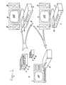
- Fig. 4 provides more details of the data logger 8, which is usually installed near by the audio and video apparatus in the establishment as is illustrated in Fig. 1 and 2.
- the data logger 8 receives the video signal from the video recorder 2 (Fig. 2) through the input 16 and supplies this video signal to a code detector 17.
- a signal is transmitted from the output of the code detector 17 to the video carrier speed detector 18 and to the run length timer 19 to activate both circuits.
- the code signal comprises a number of control signals one of which is a time signal switching on and off with a frequency of 16 Hz.
- This time signal is used in the video carrier speed detector 18 to detect whether the recorder is running at the correct tape speed.
- the data logger is able to distinguish between normal play, pasuse and fast forward or fast backward operation.
- the code detector receives code signals at regular intervals corresponding to the length of one half frame in the video signal (20 ms in European standard, 16.66 ms in US standard) and as long as the video carrier speed detector 18 provides an output signal indicating the correct carrier speed the run length timer 19 is maintained activated. However, if no code is detected for a predetermined time period or the carrier speed is not correct, the run length timer is stopped. To take into account eventual dropouts in the video signal the code detector may send a stop signal to the run length timer 19 after a predetermined delay period (e.g. after 45 milliseconds).
- the run length timer can be embodied as a simple counter counting the number of code signals received from the code detector 17. This number of codes multiplied by the time period of one half frame (20 ms or 16,66 ms) provides the exact run length time.
- the code detector 17 transmits a stop signal or another signal derived therefrom, from the output of the code detector to the memory 20 which is coupled to the data logger 8 but does not form an integrated part thereof as is explained in detail afterwards.
- the memory 20 is activated by means of this signal with the result that the run length, measured by the timer 19 is stored in this memory together with the momentaneous time and date provided by the internal clock/calendar circuit 21.
- this video carrier speed detector 18 If during the display of the video commercial the video carrier speed detector 18 detects a speed which is not within certain tolerance limits equal to the normal speed for displaying the video commercial, this video carrier speed detector 18 transmits a stop signal to the run length timer 19. The result thereof is that if the code detector 17 forwards the activation signal to the memory 20 a run length value will be stored in said memory which does not correspond to the actual duration of the video commercial.
- the audio signal registered on the video commercial carrier is checked out. For that reason the audio signal from the video recorder 2 is supplied through input 22 to a comparator 23 within the data logger 8.
- the other input of the comparator 23 is connected to terminal 24 onto which the audio signal from the output of the sound mixer 4 (Fig. 1) is received.
- Both signals are in the comparator 23 compared, e.g. by subtracting these signals from each other and the resulting signal is supplied to the level detector 24. If both signals on the terminals 22 and 24 will within reasonable limits be equal to each other then the output signal of the comparator 23 has a relatively low average level causing the level detector 24 to output a specific output signal to the audio score time 25. However, if e.g.
- the level detector 24 supplies an other specific signal to the audio score timer 25.
- the audio score timer 25 calculates in fact the ratio between both specific signals. If during the whole display of the video commercial the output of the sound mixer is within reasonable limits equal to the output of the video recorder then the audio score timer 25 will provide a value near to 100% at his output. However, if the sound signal from the video recorder is disturbed by other signals, e.g. by microphone signals received from the microphone 3, then the audio score timer will accumulate a much lower percentage, e.g. 50%. This percentage value is stored in the memory together with the signals from the run length timer 19 and the internal clock/calendar circuit 21.
- the comparison between the audio signals on the terminals 22 and 24 is done by a relatively simple comparator and level detector it is of course possible to use a more sophisticated method.
- some parameters from the audio signal are calculated e.g. the rhythm of the music, the amplitude of the signal in certain frequency bands etc. This is done both for the signal which is received from the video recorder on the terminal 22 as well as for the signal received from the sound mixer on the terminal 24. Thereafter a value for the matching of these parameters is calculated. Because sound is a statistical variable, a statistical value of the match is found.
- the value of a correct played commercial ranges from 85 to 100% matching. This value is influenced by the sound itself and by the way the video jockey fades from normal sound to the sound of the commercial.
- the data logger 8 comprises an internal power supply 26 which is able to maintain specific parts of the data logger circuit in the activated condition, even if the external power supply to the whole audio/video system is switched off.
- This internal power supply 26 comprises for that purpose e.g. a rechargeable battery, which will be recharged as soon as the external power supply is switched on again.
- the memory 20 does not necessarely form part of the data logger but is embodied as a separate component.
- this memory is housed into a so-called data cassette, and may comprise a circuit board with non volatile memory chips (RAM type chips), a bubble memory circuit, a magnetic tape or any other conceivable memory suitable for this purpose.
- RAM type chips non volatile memory chips
- bubble memory circuit bubble memory circuit
- magnetic tape magnetic tape
- the data cassette had a memory capacity of 600 records and this normally will be sufficient for about four weeks. Every cassette has its own number which makes it possible to trace cassettes, whenever a weak or damaged one is detected by the reader station.
- the reader station illustrated in Fig. 5a is in general indicated by the reference number 26 and comprises in this embodiment an interface 27 and a computer 28.
- the computer 28 may be e.g. an administrative computer which is also used for other purposes and which is installed within the office of the advertising agency. With regular intervals of e.g. two or three weeks the memories or data cassettes 20 are collected from the various discotheques and cinemas and transported to the central office of the advertising agency. The collected memories are one after the other connected to the reader station 26 as schematically illustrated in Fig. 4a.
- the function of the interface 27 is to read out sequentially the various records stored in the memory 20 and to deliver these recoreds to the computer 28 for further proceeding or just for storage thereof. If the memory is completely read out then the interface provides an erase signal to the memory to clear the memory completely.
- the reader station 26 may be embodied such that after reading and erasing the memory 20 a test routine is carried out to check the proper functioning of all parts of the data cassette specifically the memory chips thereof.
- Fig. 5b illustrates an other embodiment of the reader station referenced by 26 ⁇ which embodiment can be used in case there is no computer 28 available at the location where the collected data cassettes are read out.
- This reader station 26 ⁇ comprises an amended interface 27 ⁇ , also destined for reading out the contents of the data cassette sequentially one record after the other and to convert the read out data into signals suitable for feeding a printer mechanism 29.
- This very simplified reader station 26 ⁇ takes care that the contents of the memory 20 is in fact stored in the form of a hard copy suitable for later use or further processing.
- Fig. 6 illustrates an example of a print-out made by a printer connected to the reader station in the advertising agencies office.
- the heading line indicates the date of the print-out 12.31.86, the administrative discotheque number A901, the name of the establishment (discotheque "Night Fever"), the data logger code number 007 and the data cassette number 047.
- the subheading line indicates that the date is printed in the first column, the number and name of the video commercial are printed in the second respectively third column, the actual length of the commercial (in seconds) is printed in the fourth column, the opening hours of the discotheque are printed in the fifth column, the number of hours the discotheque is open is printed in the seventh column, and the columns 6, 8, 9 and 10 comprise the actual data concerning each showing of the video commercial.
- the column 6 provides the time of showing
- column 8 provides the number of showings on the corresponding date
- column 9 provides the actual run length (in seconds)
- column 10 provides the audio score for each time the video commercial is shown.
Applications Claiming Priority (2)
| Application Number | Priority Date | Filing Date | Title |
|---|---|---|---|
| US07/005,882 US4750034A (en) | 1987-01-21 | 1987-01-21 | Apparatus for monitoring the replay of audio/video information carriers |
| US5882 | 1987-01-21 |
Publications (2)
| Publication Number | Publication Date |
|---|---|
| EP0276036A2 true EP0276036A2 (fr) | 1988-07-27 |
| EP0276036A3 EP0276036A3 (fr) | 1990-10-31 |
Family
ID=21718190
Family Applications (1)
| Application Number | Title | Priority Date | Filing Date |
|---|---|---|---|
| EP19880200058 Withdrawn EP0276036A3 (fr) | 1987-01-21 | 1988-01-14 | Système de collecte de données |
Country Status (2)
| Country | Link |
|---|---|
| US (1) | US4750034A (fr) |
| EP (1) | EP0276036A3 (fr) |
Cited By (4)
| Publication number | Priority date | Publication date | Assignee | Title |
|---|---|---|---|---|
| EP0617871A1 (fr) * | 1991-11-22 | 1994-10-05 | Nielsen Media Research, Inc. | Systeme et procede de codage et de controle d'un programme de television realise en station d'entree |
| WO1995006985A1 (fr) * | 1993-08-31 | 1995-03-09 | Interessengemeinschaft für Rundfunkschutzrechte GmbH Schutzrechtsverwertung & Co. KG | Procede et dispositif de detection de scenes video indesirables |
| FR2723673A1 (fr) * | 1994-08-10 | 1996-02-16 | Media Control France | Dispositif d'acquisition et de transmission de signaux sonores ou audio et procede mettant en oeuvre ce dispositif |
| US7392131B2 (en) * | 2002-01-18 | 2008-06-24 | Franuhofer-Gesellschaft Zur Forderung Der Angewandten Forschung E.V. | Method for supplying a program-aided information system with specific positional information |
Families Citing this family (47)
| Publication number | Priority date | Publication date | Assignee | Title |
|---|---|---|---|---|
| US5034902A (en) * | 1986-12-09 | 1991-07-23 | Srg Schweizerische Radio-Und Fernsehgesellschaft | Method and system for ascertaining the consumption habits of a test population |
| US4885632A (en) * | 1988-02-29 | 1989-12-05 | Agb Television Research | System and methods for monitoring TV viewing system including a VCR and/or a cable converter |
| US4955070A (en) * | 1988-06-29 | 1990-09-04 | Viewfacts, Inc. | Apparatus and method for automatically monitoring broadcast band listening habits |
| US5164839A (en) * | 1988-12-27 | 1992-11-17 | Explore Technology, Inc. | Method for handling audio/video source information |
| US4963995A (en) * | 1988-12-27 | 1990-10-16 | Explore Technology, Inc. | Audio/video transceiver apparatus including compression means |
| US5319453A (en) * | 1989-06-22 | 1994-06-07 | Airtrax | Method and apparatus for video signal encoding, decoding and monitoring |
| JP2801372B2 (ja) * | 1990-06-28 | 1998-09-21 | キヤノン株式会社 | 信号処理システム,装置及び記憶装置 |
| US5969704A (en) * | 1990-09-04 | 1999-10-19 | Mikohn Gaming Corporation | Configurable led matrix display |
| AU2010192A (en) | 1991-05-21 | 1992-12-30 | Videotelecom Corp. | A multiple medium message recording system |
| US5436653A (en) * | 1992-04-30 | 1995-07-25 | The Arbitron Company | Method and system for recognition of broadcast segments |
| IT1262412B (it) * | 1993-10-27 | 1996-06-19 | Edico Srl | Ricevitore televisivo perfezionato con mezzi temporizzatori. |
| US5457807A (en) * | 1994-03-21 | 1995-10-10 | Weinblatt; Lee S. | Technique for surveying a radio or a television audience |
| US5642171A (en) * | 1994-06-08 | 1997-06-24 | Dell Usa, L.P. | Method and apparatus for synchronizing audio and video data streams in a multimedia system |
| US6836295B1 (en) | 1995-12-07 | 2004-12-28 | J. Carl Cooper | Audio to video timing measurement for MPEG type television systems |
| GB9700854D0 (en) | 1997-01-16 | 1997-03-05 | Scient Generics Ltd | Sub-audible acoustic data transmission mechanism |
| US6675383B1 (en) * | 1997-01-22 | 2004-01-06 | Nielsen Media Research, Inc. | Source detection apparatus and method for audience measurement |
| ES2296585T3 (es) * | 1998-05-12 | 2008-05-01 | Nielsen Media Research, Inc. | Sistema de medicion de audiencia para la television digital. |
| GB9917985D0 (en) | 1999-07-30 | 1999-09-29 | Scient Generics Ltd | Acoustic communication system |
| CN101282541B (zh) * | 2000-11-30 | 2011-04-06 | 因特拉松尼克斯有限公司 | 通信系统 |
| AU2211102A (en) | 2000-11-30 | 2002-06-11 | Scient Generics Ltd | Acoustic communication system |
| US20030054757A1 (en) * | 2001-09-19 | 2003-03-20 | Kolessar Ronald S. | Monitoring usage of media data with non-program data elimination |
| WO2003061285A2 (fr) * | 2001-12-24 | 2003-07-24 | Scientific Generics Limited | Systeme de legendage |
| CA2480382C (fr) * | 2002-03-29 | 2015-12-22 | Innogenetics N.V. | Methodes de detection de resistance medicamenteuse au hbv |
| US20040153787A1 (en) * | 2002-10-11 | 2004-08-05 | Eric Zucker | Process for managing messages between a set of decoders and a system of conditional access control |
| US7370212B2 (en) | 2003-02-25 | 2008-05-06 | Microsoft Corporation | Issuing a publisher use license off-line in a digital rights management (DRM) system |
| US20060242406A1 (en) | 2005-04-22 | 2006-10-26 | Microsoft Corporation | Protected computing environment |
| US8347078B2 (en) | 2004-10-18 | 2013-01-01 | Microsoft Corporation | Device certificate individualization |
| US8464348B2 (en) | 2004-11-15 | 2013-06-11 | Microsoft Corporation | Isolated computing environment anchored into CPU and motherboard |
| US8336085B2 (en) | 2004-11-15 | 2012-12-18 | Microsoft Corporation | Tuning product policy using observed evidence of customer behavior |
| US8176564B2 (en) * | 2004-11-15 | 2012-05-08 | Microsoft Corporation | Special PC mode entered upon detection of undesired state |
| US7669056B2 (en) * | 2005-03-29 | 2010-02-23 | Microsoft Corporation | Method and apparatus for measuring presentation data exposure |
| US20060106920A1 (en) * | 2004-11-15 | 2006-05-18 | Microsoft Corporation | Method and apparatus for dynamically activating/deactivating an operating system |
| US8438645B2 (en) | 2005-04-27 | 2013-05-07 | Microsoft Corporation | Secure clock with grace periods |
| US8725646B2 (en) | 2005-04-15 | 2014-05-13 | Microsoft Corporation | Output protection levels |
| US9436804B2 (en) | 2005-04-22 | 2016-09-06 | Microsoft Technology Licensing, Llc | Establishing a unique session key using a hardware functionality scan |
| US9363481B2 (en) | 2005-04-22 | 2016-06-07 | Microsoft Technology Licensing, Llc | Protected media pipeline |
| US20060265758A1 (en) | 2005-05-20 | 2006-11-23 | Microsoft Corporation | Extensible media rights |
| US8353046B2 (en) | 2005-06-08 | 2013-01-08 | Microsoft Corporation | System and method for delivery of a modular operating system |
| US9015740B2 (en) | 2005-12-12 | 2015-04-21 | The Nielsen Company (Us), Llc | Systems and methods to wirelessly meter audio/visual devices |
| US8763022B2 (en) * | 2005-12-12 | 2014-06-24 | Nielsen Company (Us), Llc | Systems and methods to wirelessly meter audio/visual devices |
| EP2030439B1 (fr) | 2006-06-15 | 2018-09-19 | The Nielsen Company (US), LLC | Procédés et appareil pour mesurer une exposition au contenu en utilisant des informations de sous-titrage codé |
| US20080184026A1 (en) * | 2007-01-29 | 2008-07-31 | Hall Martin H | Metered Personal Computer Lifecycle |
| GB2460306B (en) | 2008-05-29 | 2013-02-13 | Intrasonics Sarl | Data embedding system |
| US9124769B2 (en) | 2008-10-31 | 2015-09-01 | The Nielsen Company (Us), Llc | Methods and apparatus to verify presentation of media content |
| FR2951042A1 (fr) * | 2009-10-05 | 2011-04-08 | Korea Electronics Telecomm | Système de diffusion coopérant avec des dispositifs electroniques |
| US20110276882A1 (en) | 2010-05-04 | 2011-11-10 | Kai Buehler | Automatic grouping for users experiencing a specific broadcast media |
| US8732739B2 (en) | 2011-07-18 | 2014-05-20 | Viggle Inc. | System and method for tracking and rewarding media and entertainment usage including substantially real time rewards |
Citations (4)
| Publication number | Priority date | Publication date | Assignee | Title |
|---|---|---|---|---|
| US3651471A (en) * | 1970-03-02 | 1972-03-21 | Nielsen A C Co | Data storage and transmission system |
| US4232295A (en) * | 1979-04-13 | 1980-11-04 | Data Information Systems Corporation | Jukebox polling system |
| US4593337A (en) * | 1983-03-16 | 1986-06-03 | Alfredo Leone | Video cassette play counting, storing and reading system |
| GB2180111A (en) * | 1985-09-03 | 1987-03-18 | Video Res | System for detecting recording data of video tape recorder |
Family Cites Families (6)
| Publication number | Priority date | Publication date | Assignee | Title |
|---|---|---|---|---|
| US4547804A (en) * | 1983-03-21 | 1985-10-15 | Greenberg Burton L | Method and apparatus for the automatic identification and verification of commercial broadcast programs |
| DE3318919C2 (de) * | 1983-05-25 | 1985-03-21 | TeleMetric S.A., Internationale Gesellschaft für Fernsehzuschauerforschung, Zug | Verfahren und Vorrichtung zum Erfassen von Daten über das Fernseheinschaltverhalten von Fernsehzuschauern |
| GB8314468D0 (en) * | 1983-05-25 | 1983-06-29 | Agb Research Plc | Television monitoring |
| US4658290A (en) * | 1983-12-08 | 1987-04-14 | Ctba Associates | Television and market research data collection system and method |
| US4630108A (en) * | 1984-03-26 | 1986-12-16 | A. C. Nielsen Company | Preprogrammed over-the-air marketing research system |
| US4618995A (en) * | 1985-04-24 | 1986-10-21 | Kemp Saundra R | Automatic system and method for monitoring and storing radio user listening habits |
-
1987
- 1987-01-21 US US07/005,882 patent/US4750034A/en not_active Expired - Fee Related
-
1988
- 1988-01-14 EP EP19880200058 patent/EP0276036A3/fr not_active Withdrawn
Patent Citations (4)
| Publication number | Priority date | Publication date | Assignee | Title |
|---|---|---|---|---|
| US3651471A (en) * | 1970-03-02 | 1972-03-21 | Nielsen A C Co | Data storage and transmission system |
| US4232295A (en) * | 1979-04-13 | 1980-11-04 | Data Information Systems Corporation | Jukebox polling system |
| US4593337A (en) * | 1983-03-16 | 1986-06-03 | Alfredo Leone | Video cassette play counting, storing and reading system |
| GB2180111A (en) * | 1985-09-03 | 1987-03-18 | Video Res | System for detecting recording data of video tape recorder |
Cited By (6)
| Publication number | Priority date | Publication date | Assignee | Title |
|---|---|---|---|---|
| EP0617871A1 (fr) * | 1991-11-22 | 1994-10-05 | Nielsen Media Research, Inc. | Systeme et procede de codage et de controle d'un programme de television realise en station d'entree |
| EP0617871A4 (fr) * | 1991-11-22 | 1994-10-12 | Nielsen A C Co | Systeme et procede de codage et de controle d'un programme de television realise en station d'entree. |
| WO1995006985A1 (fr) * | 1993-08-31 | 1995-03-09 | Interessengemeinschaft für Rundfunkschutzrechte GmbH Schutzrechtsverwertung & Co. KG | Procede et dispositif de detection de scenes video indesirables |
| FR2723673A1 (fr) * | 1994-08-10 | 1996-02-16 | Media Control France | Dispositif d'acquisition et de transmission de signaux sonores ou audio et procede mettant en oeuvre ce dispositif |
| EP0698973A1 (fr) * | 1994-08-10 | 1996-02-28 | media control GmbH Medien-Analysen | Procédé et dispositif d'acquisition et de transmission de signaux sonores ou audio |
| US7392131B2 (en) * | 2002-01-18 | 2008-06-24 | Franuhofer-Gesellschaft Zur Forderung Der Angewandten Forschung E.V. | Method for supplying a program-aided information system with specific positional information |
Also Published As
| Publication number | Publication date |
|---|---|
| US4750034A (en) | 1988-06-07 |
| EP0276036A3 (fr) | 1990-10-31 |
Similar Documents
| Publication | Publication Date | Title |
|---|---|---|
| US4750034A (en) | Apparatus for monitoring the replay of audio/video information carriers | |
| US5703795A (en) | Apparatus and methods for accessing information relating to radio and television programs | |
| USRE38600E1 (en) | Apparatus and methods for accessing information relating to radio television programs | |
| CA1301312C (fr) | Appareil d'enregistrement rapide sur bande magnetique de morceaux musicaux preselectionnes | |
| US3990710A (en) | Coin-operated recording machine | |
| US4170782A (en) | Programming and selection monitoring system for television receivers | |
| US5055947A (en) | Cassette for storing data in a solid state memory in lieu of tape | |
| US3696335A (en) | Credit verification system | |
| EP0467208A1 (fr) | Système numérique d'information | |
| US3708891A (en) | Spoken questionnaire method and apparatus | |
| CN102054411B (zh) | 一种音频广告自动播放装置 | |
| US3594505A (en) | Information distribution system | |
| ITRM960585A1 (it) | Tecnica di gestione del servizio di pubblicita' fonica su terminali telefonici | |
| JPH03118690A (ja) | 情報提供装置 | |
| JPH0247766A (ja) | 広告広報通信表示装置 | |
| JPH064560A (ja) | Cd新譜の案内・予約装置 | |
| JP3244566B2 (ja) | 磁気情報の記録再生装置 | |
| Blethen | A Method for Qualifying Recorded Tone Bursts | |
| JP3092934B2 (ja) | カセットテープの自動販売機 | |
| JPH10232685A (ja) | クーポンサービスの不正利用防止方法に特徴を有する通信カラオケシステムとカラオケ演奏端末およびカラオケ装置 | |
| JP2000149134A (ja) | 自動販売機 | |
| GB1567332A (en) | Recording apparatus | |
| JPS6025630Y2 (ja) | 券売機 | |
| EP0809899A1 (fr) | Procede et dispositif d'acces a des informations relatives a des emissions de radio et de television | |
| Wulfemeyer | Radio-TV Classes Earn Regular Slots on Local Stations |
Legal Events
| Date | Code | Title | Description |
|---|---|---|---|
| PUAI | Public reference made under article 153(3) epc to a published international application that has entered the european phase |
Free format text: ORIGINAL CODE: 0009012 |
|
| AK | Designated contracting states |
Kind code of ref document: A2 Designated state(s): AT BE CH DE ES FR GB IT LI NL SE |
|
| PUAL | Search report despatched |
Free format text: ORIGINAL CODE: 0009013 |
|
| AK | Designated contracting states |
Kind code of ref document: A3 Designated state(s): AT BE CH DE ES FR GB IT LI NL SE |
|
| 17P | Request for examination filed |
Effective date: 19901130 |
|
| 17Q | First examination report despatched |
Effective date: 19930302 |
|
| STAA | Information on the status of an ep patent application or granted ep patent |
Free format text: STATUS: THE APPLICATION IS DEEMED TO BE WITHDRAWN |
|
| 18D | Application deemed to be withdrawn |
Effective date: 19930713 |