EP0274760B1 - System comprising freely suspended ducts - Google Patents
System comprising freely suspended ducts Download PDFInfo
- Publication number
- EP0274760B1 EP0274760B1 EP87119421A EP87119421A EP0274760B1 EP 0274760 B1 EP0274760 B1 EP 0274760B1 EP 87119421 A EP87119421 A EP 87119421A EP 87119421 A EP87119421 A EP 87119421A EP 0274760 B1 EP0274760 B1 EP 0274760B1
- Authority
- EP
- European Patent Office
- Prior art keywords
- duct
- support element
- fact
- support
- fasteners
- Prior art date
- Legal status (The legal status is an assumption and is not a legal conclusion. Google has not performed a legal analysis and makes no representation as to the accuracy of the status listed.)
- Expired - Lifetime
Links
- 239000002351 wastewater Substances 0.000 claims description 7
- 238000009434 installation Methods 0.000 claims description 4
- 238000005452 bending Methods 0.000 claims description 3
- 239000000463 material Substances 0.000 claims description 2
- 239000012530 fluid Substances 0.000 claims 1
- 239000010865 sewage Substances 0.000 abstract description 8
- XLYOFNOQVPJJNP-UHFFFAOYSA-N water Substances O XLYOFNOQVPJJNP-UHFFFAOYSA-N 0.000 abstract description 2
- 239000000725 suspension Substances 0.000 description 6
- 230000000694 effects Effects 0.000 description 2
- 238000010276 construction Methods 0.000 description 1
- 238000009413 insulation Methods 0.000 description 1
- 230000008646 thermal stress Effects 0.000 description 1
Images

Classifications
-
- F—MECHANICAL ENGINEERING; LIGHTING; HEATING; WEAPONS; BLASTING
- F16—ENGINEERING ELEMENTS AND UNITS; GENERAL MEASURES FOR PRODUCING AND MAINTAINING EFFECTIVE FUNCTIONING OF MACHINES OR INSTALLATIONS; THERMAL INSULATION IN GENERAL
- F16L—PIPES; JOINTS OR FITTINGS FOR PIPES; SUPPORTS FOR PIPES, CABLES OR PROTECTIVE TUBING; MEANS FOR THERMAL INSULATION IN GENERAL
- F16L3/00—Supports for pipes, cables or protective tubing, e.g. hangers, holders, clamps, cleats, clips, brackets
- F16L3/08—Supports for pipes, cables or protective tubing, e.g. hangers, holders, clamps, cleats, clips, brackets substantially surrounding the pipe, cable or protective tubing
-
- F—MECHANICAL ENGINEERING; LIGHTING; HEATING; WEAPONS; BLASTING
- F16—ENGINEERING ELEMENTS AND UNITS; GENERAL MEASURES FOR PRODUCING AND MAINTAINING EFFECTIVE FUNCTIONING OF MACHINES OR INSTALLATIONS; THERMAL INSULATION IN GENERAL
- F16B—DEVICES FOR FASTENING OR SECURING CONSTRUCTIONAL ELEMENTS OR MACHINE PARTS TOGETHER, e.g. NAILS, BOLTS, CIRCLIPS, CLAMPS, CLIPS OR WEDGES; JOINTS OR JOINTING
- F16B2/00—Friction-grip releasable fastenings
- F16B2/02—Clamps, i.e. with gripping action effected by positive means other than the inherent resistance to deformation of the material of the fastening
- F16B2/14—Clamps, i.e. with gripping action effected by positive means other than the inherent resistance to deformation of the material of the fastening using wedges
Landscapes
- Engineering & Computer Science (AREA)
- General Engineering & Computer Science (AREA)
- Mechanical Engineering (AREA)
- Supports For Pipes And Cables (AREA)
- Coupling Device And Connection With Printed Circuit (AREA)
- Monitoring And Testing Of Exchanges (AREA)
- Manufacturing Of Electric Cables (AREA)
- Pipe Accessories (AREA)
- Sewage (AREA)
Abstract
Description
Die vorliegende Erfindung betrifft eine Anlage mit mindestens einer zur Medienführung vorgesehenen freiliegenden Rohrleitung, welche mittels Haltern an Bautenteilen lösbar befestigt ist sowie Halter zum Halten von Rohrleitungen und Tragelementen in solchen Anlagen.The present invention relates to a system with at least one exposed pipeline for media guidance, which is releasably attached to structural parts by means of holders and holders for holding pipes and support elements in such systems.
Bei aus Kunststoff bestehenden Abwasserleitungen, welche an Gebäudeteilen aufgehängt oder abgestützt werden, besteht die Schwierigkeit, dass diese Leitungen entweder geringe Stützweiten haben und daher eine grosse Anzahl von Aufhänge- oder Abstützelementen für eine vorgegebene Leitungslänge benötigt wird, oder dass bei weiten Stützlängen sich die Abwasserleitung durchbiegt, sei dies bedingt durch das eigene Gewicht, sei dies durch Wärmedehnungen, welch letztere sich nicht nur in Vertikalebenen auswirken.In the case of waste water pipes made of plastic, which are suspended or supported on parts of the building, there is the difficulty that these pipes either have small spans and therefore a large number of suspension or support elements are required for a given pipe length, or that the waste water pipe is extended for long pipe lengths deflects, be it due to its own weight or be it due to thermal expansion, the latter not only having an effect in vertical planes.
Die bisherigen Aufhängungen sind als sog. Fixpunkt-Aufhänger konzipiert, was bei wesentlichen Temperaturunterschieden der Leitungen zu unerwünschten Wärmespannungen und gegebenenfalls Formänderungen führen könnte.The previous suspensions are designed as so-called fixed-point suspensions, which could lead to undesirable thermal stresses and, if necessary, changes in shape if there are significant temperature differences in the cables.
So zeigt beispielsweise die US-A-2 889 145 eine Vorrichtung zur Aufnahme freiliegender Heissluftleitungen u. dgl., wobei die Stützelemente einer derartigen Anlage verstellbar sind, um den Rohraussendimensionen angepasst zu werden. Hierbei dient die aufzuhängende oder zu stützende Heissluftleitung nicht nur der Medienführung, sondern sie muss zusammen mit dem Abstand der einzelnen Stützelemente so dimensioniert sein, dass sie auch die auftretenden Kräfte, insbesondere ihr Eigengewicht, ohne massgebliche Deformation ertragen kann. Diese Doppelfunktion, nämlich das Führen des Mediums in der Rohrleitung und die festigkeitsgerechte Dimensionierung zwingen zu unerwünschten Kompromissen und verhindern oftmals die Verwendung des für das mediumführende Rohr optimalen Materials.For example, US-A-2 889 145 shows a device for receiving exposed hot air lines and the like. Like., The support elements of such a system are adjustable to be adapted to the outer tube dimensions. Here serves the Hot air line to be suspended or supported not only the media guide, but it must be dimensioned together with the distance between the individual support elements so that it can also withstand the forces that occur, in particular its own weight, without significant deformation. This double function, namely the guiding of the medium in the pipeline and the dimensioning according to strength, force undesirable compromises and often prevent the use of the optimal material for the medium-carrying pipe.
Die Befestigungsfrage derartiger medienführender Leitungen und ihrer Stütz- und Aufhängeelemente ist auf viele spezielle Arten beantwortet worden, wie dies beispielsweise die FR-A 2 220 648, FR-A 2 409 411 und FR-A 2 549 543 sowie die US-A 4 167 355, US-A 3 506 227 und das DE-U-7 126 824 zeigen.The question of fastening such media-carrying lines and their support and suspension elements has been answered in many special ways, such as FR-A 2 220 648, FR-A 2 409 411 and FR-A 2 549 543 and US-A 4 167 355, US-A 3 506 227 and DE-U-7 126 824.
Alle diese bekannten Aufhängevorrichtungen mit Befestigungselementen dienen zur Festhaltung freiliegender Rohrleitungen oder zeigen Verbindungselemente für aus Rohren zusammengesetzte Traggerüste für Bauten. Bei letzteren findet eine kreuzweise Anordnung der Rohre statt. Dazu sind entsprechende Verbindungselemente vorgesehen.All of these known suspension devices with fastening elements serve to hold exposed pipelines or show connecting elements for supporting scaffolds composed of pipes for buildings. In the latter, the tubes are arranged crosswise. Corresponding connecting elements are provided for this.
In der EP-A- 0 160 890 ist zwar ein auf einem Stützgerüst befestigter Abgaskanal offenbart, welcher auf einer Tragkonstruktion mit Längsstreben über seine Längsflansche abgestützt ist. Diese Konstruktion eignet sich nur zum Verlegen von Rohrleitungen auf Bo denstützgerüsten und nicht zum Aufhängen an Decken oder Seitenwänden, da diese Stützen dafür, im Hinblick auf zu stützende Abgaskanäle, im Aufbau zu kompliziert und gewichtsmässig viel zu schwer sind.EP-A-0 160 890 does indeed disclose an exhaust gas duct which is fastened to a supporting frame and which is supported on a supporting structure with longitudinal struts via its longitudinal flanges. This construction is only suitable for laying pipes on Bo support scaffolding and not for hanging on ceilings or side walls, since these supports are too complicated in structure and much too heavy in terms of weight in terms of exhaust gas ducts to be supported.
Zum Stande der Technik gehört ferner die EP-A- 0 165 370, welche eine Aufhängevorrichtung für Rohre zeigt. Die das Rohr tragenden Rohrhalter sind in sich äusserst stabil und leicht höhenverstellbar ausgebildet.The prior art also includes EP-A-0 165 370, which shows a suspension device for pipes. The tube holder carrying the tube is extremely stable and is easily adjustable in height.
Sie sind jedoch zur Aufnahme nur eines Rohres vorgesehen, so dass, entsprechend der Biegesteifigkeit des Rohres, der Abstand der sich folgenden Rohrhalter relativ klein wird und damit insbesondere bei aus Kunststoff bestehenden Abwasserleitungen die vorbeschriebenen geringen Stützweiten in Kauf genommen werden müssen.However, they are provided for receiving only one pipe, so that, depending on the bending stiffness of the pipe, the distance between the pipe holders that follow is relatively small and, in particular in the case of waste water pipes made of plastic, the above-mentioned small spans must be accepted.
Die Verwendung derartiger Rohrhalter kann daher die im folgenden erläuterte Aufgabe nicht lösen, denn das aufzuhängende Rohr ist durch keinen zusätzlichen Träger verstärkt und der Abstand der Rohrhalter ist einzig und allein aufgrund der Biegefestigkeit des aufgehängten Rohres festgelegt.The use of such pipe holder can therefore not solve the task explained below, because the pipe to be hung is not reinforced by an additional support and the distance between the pipe holder is determined solely by the bending strength of the suspended pipe.
Die vorliegende Erfindung bezweckt die Schaffung der Möglichkeit, solche Abwasserleitungen mit relativ grossen Stützlängen montieren zu können, ohne dabei eine, den Wasserabfluss hemmende oder sonstwie merkliche Deformation der Abwasserleitung in Kauf nehmen zu müssen.The present invention aims to provide the possibility of being able to mount such sewage pipes with relatively large support lengths without having to accept a deformation of the sewage pipe that inhibits water drainage or is otherwise noticeable.
Die Lösung dieses Problems ermöglicht eine Verbindungsvorrichtung, welche durch einen der Ansprüche gekennzeichnet ist.The solution to this problem enables a connection device which is characterized by one of the claims.
Die Erfindung wird anschliessend beispielsweise anhand einer Figur erläutert.The invention is subsequently explained, for example, using a figure.
Es zeigen:
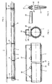
- Fig. 1
- eine an einer Decke montierte Abwasserleitung,
- Fig. 2
- eine an einer Decke befestigbare Rohrschelle, deren unterer Teil als Verbindungsvorrichtung ausgebildet und mit einem Träger mittels Keil lösbar verbunden ist,
- Fig. 3
- eine Verbindungsvorrichtung zum Verbinden zweier koaxial liegender Trägerrohre,
- Fig. 4
- einen Querschnitt durch die Vorrichtung nach Fig. 3,
- Fig. 5
- einen Keil in verschiedenen Darstellungen.
- Fig. 1
- a sewer pipe mounted on a ceiling,
- Fig. 2
- a pipe clamp that can be attached to a ceiling, the lower part of which is designed as a connecting device and is detachably connected to a carrier by means of a wedge
- Fig. 3
- a connecting device for connecting two coaxial carrier tubes,
- Fig. 4
- 3 shows a cross section through the device according to FIG. 3,
- Fig. 5
- a wedge in different representations.
In Fig. 1 ist ein Teil einer Decke 1 dargestellt, an der eine Abwasserleitung 2, vorzugsweise aus Kunststoff bestehend, aufgehängt bzw. abgestützt ist.In Fig. 1, a part of a
Die Abwasserleitung 2 besteht aus einzelnen Leitungsteilen, welche mittels Elektromuffen 3 miteinander wasserdicht verschweisst sind. Die Abwasserleitung 2 ist auf einem Träger 4 abgestützt, welcher Träger irgend einen Querschnitt, sei dies rund, quadratisch viereckig oder eine andere Profilform aufweisen kann. Er dient der Halterung der Abwasserleitung 2 und schützt diese vor Durchbiegung. Die Abwasserleitung 2 ist in einer Rohrschelle 6 gehaltert und gegebenenfalls mit einer Isolation 9 versehen. Zwischen den Rohrschellen 6 sind Führungsstützen 8 angeordnet, so dass die freie Stützweite zwischen je zwei Rohrschellen 6 bei der Rohrlänge von 6 m zwischen zwei sich folgenden Elektromuffen 3, wie Fig. 1 zeigt, z.B. 3 m beträgt und zwischen einer Führungsstütze 8 und der folgenden Rohrschelle 6 1,50 m.The
Die in Fig. 2 dargestellte Rohrschelle 6 weist einen Oberteil 11 mit einem Gewindezapfen 12, einer Deckenplatte 13 und einer Gewindemuffe 14 auf. Die Deckenplatte ist mit Schlitzen versehen, um sie an der Decke lagegerecht montieren zu können. Der Unterteil 17 der Rohrschelle 6 ist zusätzlich mit einem, hier U-förmig ausgebildeten, Führungselement 18 versehen, dessen zwei Schenkel je eine Oeffnung 19 aufweisen. Diese dienen der Aufnahme eines Keils 20. Dieser Keil 20 ist in Fig. 5 dargestellt. Er ist sowohl in seiner Höhe als auch in seiner Breite konisch. Daher sind seine dachförmigen Querschnitte geometrisch ähnlich. Seine seitlichen Auflageflächen 21 ergeben mit zwei unteren Kanten 31 und 32, welche zusammenlaufen, den Sperreffekt. Die Konizitäten sichern die Selbstsperrung. Der Keil ist durch eine Stanzung und eine Biegung billigst herstellbar.The
Es ist aber auch möglich, zum Sperren des Keils eine Sperrfläche, vorzugsweise aufgerauht, beispielsweise mit einer Zahnung zu versehen, welche ein selbsttätiges Lösen des Keils, beispielsweise durch Erschütterungen, verhütet.However, it is also possible to provide a locking surface, preferably roughened, for locking the wedge, for example with a toothing which prevents the wedge from loosening automatically, for example due to vibrations.
Eine weitere Möglichkeit der Ausbildung einer derartigen Verbindungsvorrichtung zeigen die Fig. 3 und 4, gemäss welchen zwei Trägerrohre 4 miteinander durch eine Verbindungsmuffe 25 verbunden werden. Der untere Teil der Verbindungsmuffe 25 ist als Schelle 26 ausgebildet, den entsprechenden Abmessungen der Trägerrohre 4 angepasst, die hier einen runden Querschnitt aufweisen. Die Schelle 26 ist mit einem darüberliegenden Bügel 27 mit vier Oeffnungspaaren 28 zur Aufnahme von vier Keilen 20 versehen. Diese muffenförmige Verbindungsvorrichtung dient der Verbindung zweier Rohre.A further possibility of forming such a connecting device is shown in FIGS. 3 and 4, according to which two support tubes 4 pass through each other a connecting
Die Führungsstützen 8 sind analog ausgebildet, wie die Rohrschellen 6. Sie stützen sich indessen nur auf dem Träger 4 ab, ohne mit der Decke 1 in Hängeverbindung zu stehen.The guide supports 8 are designed analogously to the
Die Montage der Abwasserleitung 2 erfolgt äusserst einfach, da ein Verschieben von Rohrschellen und Stützen auf dem Träger einfach zu bewerkstelligen ist und die Fixierung mittels Keilen 20 mühelos und sicher eine feste und trotzdem lösbare Verbindung darstellt. Auf diese Weise ist es u.a. möglich, Abwasserleitungen aus Kunststoff, ohne schädliche Deformationsmöglichkeiten, starr zu montieren.The installation of the
In der Praxis wird häufig die Lage von Rohrschelle 6 und Träger 4 vertauscht, d.h. gemäss Fig. 2 ist der Träger 4 oben und die Rohrschelle 6 wird unter dem Träger angeordnet.In practice, the position of
Claims (7)
- Installation with at least one duct (2) foreseen for fluid transportation and freely suspended to a ceiling or a side wall and, more specifically, a waste water duct (2) made of plastic material and removably assembled to these building elements (1) by means of fasteners (6, 18) and whereby at least one additional support element (4) is mounted along the duct (2), characterized by the fact that the support element (4) used exclusively to support the duct (2) is connected, in order to increase the bending stiffness of the duct (2) to fasteners (6, 18) as well as to other fasteners removably assembling only the support element (4) and the duct (2) by means of wedges (20) inserted into the fasteners (6, 8, 18) into at least two openings opposed to each other.
- Installation according to claim 1, characterized by the fact that the duct (2) is supported by the support element (4) or is suspended to it, in order to withstand forces acting on the duct (2) and, more specifically, those caused by the weights.
- Fastener for securing the ducts (2) and the support elements (4) in the installations according to one of the claims 1 or 2, characterized by the fact that this fastener is designed in order that it supports the duct (2) and the support element (4), has at least one passage as well as one clamp (6), is equipped with a passage part (18) to receive the support element (4), includes also at least two openings opposed to each other (19, 28) and at least one wedge (20) and is foreseen in order to partly surround at least one of the support elements (4,4) to be assembled together and that the wedge (20) must be inserted into two openings opposed to each other (19, 28) in order to removably assemble this way the support elements (4, 25) and the fasteners (26).
- Fastener according to claim 3, characterized by the fact that the passage part (18), designed to receive the support element (4), is located under the clamp (6) while a gap remains possibly between the pipe and the support element.
- Fastener according to claim 3 or 4, characterized by the fact that the support element (4) is made of a tube or a section.
- Fastener according to one of claims 3 to 5, characterized by a self-locking wedge with double conicity (20), possibly with a linear contact surface (31, 32).
- Fastener according to one of claims 3 to 6, characterized by the fact that it is equipped with a ceiling plate (13).
Priority Applications (1)
| Application Number | Priority Date | Filing Date | Title |
|---|---|---|---|
| AT87119421T ATE61085T1 (en) | 1987-01-15 | 1987-12-31 | PLANT WITH ONE SUSPENDED PIPELINE. |
Applications Claiming Priority (2)
| Application Number | Priority Date | Filing Date | Title |
|---|---|---|---|
| CH124/87 | 1987-01-15 | ||
| CH12487 | 1987-01-15 |
Publications (2)
| Publication Number | Publication Date |
|---|---|
| EP0274760A1 EP0274760A1 (en) | 1988-07-20 |
| EP0274760B1 true EP0274760B1 (en) | 1991-02-27 |
Family
ID=4179803
Family Applications (1)
| Application Number | Title | Priority Date | Filing Date |
|---|---|---|---|
| EP87119421A Expired - Lifetime EP0274760B1 (en) | 1987-01-15 | 1987-12-31 | System comprising freely suspended ducts |
Country Status (4)
| Country | Link |
|---|---|
| EP (1) | EP0274760B1 (en) |
| AT (1) | ATE61085T1 (en) |
| DE (1) | DE3768242D1 (en) |
| DK (1) | DK170183B1 (en) |
Cited By (1)
| Publication number | Priority date | Publication date | Assignee | Title |
|---|---|---|---|---|
| EP1043531A2 (en) | 1999-04-06 | 2000-10-11 | Geberit Technik Ag | Holding device for a water pipe |
Families Citing this family (2)
| Publication number | Priority date | Publication date | Assignee | Title |
|---|---|---|---|---|
| NL1020580C2 (en) | 2002-05-13 | 2003-11-14 | Walraven J Van Bv | Stirrup for pipe or similar is for fixture to profile and has ring-shaped body for accommodation of pipe, being provided with clamp devices for its fixture to profile |
| DK1411286T3 (en) | 2002-10-16 | 2007-03-05 | Geberit Technik Ag | Pipe carrier |
Citations (2)
| Publication number | Priority date | Publication date | Assignee | Title |
|---|---|---|---|---|
| EP0160890A2 (en) * | 1984-04-26 | 1985-11-13 | Toschi Produktions-GmbH | Smoke conduit affixable to a framework |
| EP0165370A1 (en) * | 1984-05-14 | 1985-12-27 | Jan Vrijhof | Suspension device |
Family Cites Families (7)
| Publication number | Priority date | Publication date | Assignee | Title |
|---|---|---|---|---|
| DE7126824U (en) * | 1900-01-01 | Badische Eisen-U. Blechwarenfabrik Gmbh | ||
| US2889145A (en) * | 1955-03-07 | 1959-06-02 | Charles G Hoffman | Apparatus for supporting hot air ducts and the like |
| US3506227A (en) * | 1967-11-06 | 1970-04-14 | Trw Inc | Hanger for elongate members |
| FR2220648A1 (en) * | 1973-03-07 | 1974-10-04 | Zaidan Joseph | |
| SE403176B (en) * | 1976-12-22 | 1978-07-31 | Svenska Kram Ab | LOSTAGBAR SOCKET AROUND ROD OR SOLID PROFILE WITH RECTANGULAR CROSS SECTION |
| FR2409411A1 (en) * | 1977-11-22 | 1979-06-15 | Entrepose | Joint for assembling tubular framework - has apertured U=shaped clip which is secured by taper key acting to force tubes apart |
| FR2549543A1 (en) * | 1983-07-18 | 1985-01-25 | Bertoni Daniel | A key with two nonparallel faces equipped with a locking means |
-
1987
- 1987-12-31 EP EP87119421A patent/EP0274760B1/en not_active Expired - Lifetime
- 1987-12-31 DE DE8787119421T patent/DE3768242D1/en not_active Expired - Lifetime
- 1987-12-31 AT AT87119421T patent/ATE61085T1/en not_active IP Right Cessation
-
1988
- 1988-01-06 DK DK002988A patent/DK170183B1/en not_active Application Discontinuation
Patent Citations (2)
| Publication number | Priority date | Publication date | Assignee | Title |
|---|---|---|---|---|
| EP0160890A2 (en) * | 1984-04-26 | 1985-11-13 | Toschi Produktions-GmbH | Smoke conduit affixable to a framework |
| EP0165370A1 (en) * | 1984-05-14 | 1985-12-27 | Jan Vrijhof | Suspension device |
Cited By (1)
| Publication number | Priority date | Publication date | Assignee | Title |
|---|---|---|---|---|
| EP1043531A2 (en) | 1999-04-06 | 2000-10-11 | Geberit Technik Ag | Holding device for a water pipe |
Also Published As
| Publication number | Publication date |
|---|---|
| DE3768242D1 (en) | 1991-04-04 |
| EP0274760A1 (en) | 1988-07-20 |
| DK2988D0 (en) | 1988-01-06 |
| DK2988A (en) | 1988-07-16 |
| ATE61085T1 (en) | 1991-03-15 |
| DK170183B1 (en) | 1995-06-06 |
Similar Documents
| Publication | Publication Date | Title |
|---|---|---|
| DE69819838T2 (en) | Device for assembling two pipes | |
| AT408139B (en) | INSTALLATION DEVICE FOR PIPELINES | |
| DE3921719A1 (en) | CEILING COVERING | |
| DE3936198C2 (en) | ||
| EP0274760B1 (en) | System comprising freely suspended ducts | |
| CH667121A5 (en) | HOLDING DEVICE FOR THE PRE-WALL MOUNTING OF SANITARY APPLIANCES, FITTINGS, PIPE PARTS AND PIPES. | |
| DE2743819C3 (en) | Ceiling heating for halls and other buildings | |
| DE1907473B2 (en) | Device for holding installation pipelines | |
| DE19707592C2 (en) | Ceiling duct for an exhaust pipe from a heating system | |
| DE102005000174A1 (en) | Support for installations in the field of building services and industry | |
| EP3757305B1 (en) | Working space | |
| DE8206901U1 (en) | INSTALLATION FRAME WITH PRECAST COMPONENTS FOR SANITARY OBJECTS AND THE LIKE. | |
| DE4130011A1 (en) | Fastening element for pipes - has holder and two arms defining minimum two sections with openings | |
| DE2519641A1 (en) | HOLDER FOR HOLDING INSTALLATION PARTS | |
| DE2902759C2 (en) | Device for fastening pipe profiles to load-bearing surfaces | |
| DE19717956A1 (en) | Cable route retaining and mounting system e.g. for power plant | |
| DE19506661C2 (en) | Hangers for pipes | |
| WO1993016246A1 (en) | Device for sound-damping in buildings | |
| DE10029475B4 (en) | Device for attachment and axial fixing of a pipeline | |
| DE10161720C1 (en) | Device, for fixing hanging pipes onto e.g. ceilings, comprises fixing brackets arranged opposite a web for closing the space formed between the side cheeks and the web | |
| AT332066B (en) | ARRANGEMENT WITH HANGING CEILING | |
| DE3814912C2 (en) | ||
| DD220995A1 (en) | PIPE FITTING | |
| CH672360A5 (en) | ||
| DD147127A1 (en) | Installation Device |
Legal Events
| Date | Code | Title | Description |
|---|---|---|---|
| PUAI | Public reference made under article 153(3) epc to a published international application that has entered the european phase |
Free format text: ORIGINAL CODE: 0009012 |
|
| AK | Designated contracting states |
Kind code of ref document: A1 Designated state(s): AT BE CH DE IT LI NL |
|
| 17P | Request for examination filed |
Effective date: 19890111 |
|
| 17Q | First examination report despatched |
Effective date: 19890612 |
|
| ITF | It: translation for a ep patent filed |
Owner name: STUDIO INGG. FISCHETTI & WEBER |
|
| GRAA | (expected) grant |
Free format text: ORIGINAL CODE: 0009210 |
|
| AK | Designated contracting states |
Kind code of ref document: B1 Designated state(s): AT BE CH DE IT LI NL |
|
| REF | Corresponds to: |
Ref document number: 61085 Country of ref document: AT Date of ref document: 19910315 Kind code of ref document: T |
|
| REF | Corresponds to: |
Ref document number: 3768242 Country of ref document: DE Date of ref document: 19910404 |
|
| PLBE | No opposition filed within time limit |
Free format text: ORIGINAL CODE: 0009261 |
|
| STAA | Information on the status of an ep patent application or granted ep patent |
Free format text: STATUS: NO OPPOSITION FILED WITHIN TIME LIMIT |
|
| 26N | No opposition filed | ||
| PGFP | Annual fee paid to national office [announced via postgrant information from national office to epo] |
Ref country code: BE Payment date: 20010315 Year of fee payment: 14 |
|
| PG25 | Lapsed in a contracting state [announced via postgrant information from national office to epo] |
Ref country code: BE Free format text: LAPSE BECAUSE OF NON-PAYMENT OF DUE FEES Effective date: 20011231 |
|
| BERE | Be: lapsed |
Owner name: GEBERIT A.G. ARMATUREN & APPARATEFABRIK Effective date: 20011231 |
|
| PGFP | Annual fee paid to national office [announced via postgrant information from national office to epo] |
Ref country code: NL Payment date: 20051204 Year of fee payment: 19 |
|
| PGFP | Annual fee paid to national office [announced via postgrant information from national office to epo] |
Ref country code: AT Payment date: 20051213 Year of fee payment: 19 |
|
| PG25 | Lapsed in a contracting state [announced via postgrant information from national office to epo] |
Ref country code: IT Free format text: LAPSE BECAUSE OF NON-PAYMENT OF DUE FEES;WARNING: LAPSES OF ITALIAN PATENTS WITH EFFECTIVE DATE BEFORE 2007 MAY HAVE OCCURRED AT ANY TIME BEFORE 2007. THE CORRECT EFFECTIVE DATE MAY BE DIFFERENT FROM THE ONE RECORDED. Effective date: 20051231 |
|
| PGFP | Annual fee paid to national office [announced via postgrant information from national office to epo] |
Ref country code: DE Payment date: 20060103 Year of fee payment: 19 |
|
| PGFP | Annual fee paid to national office [announced via postgrant information from national office to epo] |
Ref country code: CH Payment date: 20060227 Year of fee payment: 19 |
|
| PG25 | Lapsed in a contracting state [announced via postgrant information from national office to epo] |
Ref country code: LI Free format text: LAPSE BECAUSE OF NON-PAYMENT OF DUE FEES Effective date: 20061231 Ref country code: CH Free format text: LAPSE BECAUSE OF NON-PAYMENT OF DUE FEES Effective date: 20061231 |
|
| PG25 | Lapsed in a contracting state [announced via postgrant information from national office to epo] |
Ref country code: NL Free format text: LAPSE BECAUSE OF NON-PAYMENT OF DUE FEES Effective date: 20070701 |
|
| PG25 | Lapsed in a contracting state [announced via postgrant information from national office to epo] |
Ref country code: DE Free format text: LAPSE BECAUSE OF NON-PAYMENT OF DUE FEES Effective date: 20070703 |
|
| REG | Reference to a national code |
Ref country code: CH Ref legal event code: PL |
|
| NLV4 | Nl: lapsed or anulled due to non-payment of the annual fee |
Effective date: 20070701 |
|
| PG25 | Lapsed in a contracting state [announced via postgrant information from national office to epo] |
Ref country code: AT Free format text: LAPSE BECAUSE OF NON-PAYMENT OF DUE FEES Effective date: 20061231 |