EP0274706A2 - Disposable container - Google Patents
Disposable container Download PDFInfo
- Publication number
- EP0274706A2 EP0274706A2 EP87118780A EP87118780A EP0274706A2 EP 0274706 A2 EP0274706 A2 EP 0274706A2 EP 87118780 A EP87118780 A EP 87118780A EP 87118780 A EP87118780 A EP 87118780A EP 0274706 A2 EP0274706 A2 EP 0274706A2
- Authority
- EP
- European Patent Office
- Prior art keywords
- lid
- edge
- closure
- disposable container
- groove
- Prior art date
- Legal status (The legal status is an assumption and is not a legal conclusion. Google has not performed a legal analysis and makes no representation as to the accuracy of the status listed.)
- Withdrawn
Links
Images


Classifications
-
- B—PERFORMING OPERATIONS; TRANSPORTING
- B65—CONVEYING; PACKING; STORING; HANDLING THIN OR FILAMENTARY MATERIAL
- B65D—CONTAINERS FOR STORAGE OR TRANSPORT OF ARTICLES OR MATERIALS, e.g. BAGS, BARRELS, BOTTLES, BOXES, CANS, CARTONS, CRATES, DRUMS, JARS, TANKS, HOPPERS, FORWARDING CONTAINERS; ACCESSORIES, CLOSURES, OR FITTINGS THEREFOR; PACKAGING ELEMENTS; PACKAGES
- B65D43/00—Lids or covers for rigid or semi-rigid containers
- B65D43/02—Removable lids or covers
- B65D43/0202—Removable lids or covers without integral tamper element
- B65D43/0204—Removable lids or covers without integral tamper element secured by snapping over beads or projections
- B65D43/0212—Removable lids or covers without integral tamper element secured by snapping over beads or projections only on the outside, or a part turned to the outside, of the mouth
-
- A—HUMAN NECESSITIES
- A61—MEDICAL OR VETERINARY SCIENCE; HYGIENE
- A61B—DIAGNOSIS; SURGERY; IDENTIFICATION
- A61B50/00—Containers, covers, furniture or holders specially adapted for surgical or diagnostic appliances or instruments, e.g. sterile covers
- A61B50/30—Containers specially adapted for packaging, protecting, dispensing, collecting or disposing of surgical or diagnostic appliances or instruments
- A61B50/36—Containers specially adapted for packaging, protecting, dispensing, collecting or disposing of surgical or diagnostic appliances or instruments for collecting or disposing of used articles
-
- B—PERFORMING OPERATIONS; TRANSPORTING
- B65—CONVEYING; PACKING; STORING; HANDLING THIN OR FILAMENTARY MATERIAL
- B65D—CONTAINERS FOR STORAGE OR TRANSPORT OF ARTICLES OR MATERIALS, e.g. BAGS, BARRELS, BOTTLES, BOXES, CANS, CARTONS, CRATES, DRUMS, JARS, TANKS, HOPPERS, FORWARDING CONTAINERS; ACCESSORIES, CLOSURES, OR FITTINGS THEREFOR; PACKAGING ELEMENTS; PACKAGES
- B65D2543/00—Lids or covers essentially for box-like containers
- B65D2543/00009—Details of lids or covers for rigid or semi-rigid containers
- B65D2543/00018—Overall construction of the lid
- B65D2543/00064—Shape of the outer periphery
- B65D2543/00074—Shape of the outer periphery curved
- B65D2543/00092—Shape of the outer periphery curved circular
-
- B—PERFORMING OPERATIONS; TRANSPORTING
- B65—CONVEYING; PACKING; STORING; HANDLING THIN OR FILAMENTARY MATERIAL
- B65D—CONTAINERS FOR STORAGE OR TRANSPORT OF ARTICLES OR MATERIALS, e.g. BAGS, BARRELS, BOTTLES, BOXES, CANS, CARTONS, CRATES, DRUMS, JARS, TANKS, HOPPERS, FORWARDING CONTAINERS; ACCESSORIES, CLOSURES, OR FITTINGS THEREFOR; PACKAGING ELEMENTS; PACKAGES
- B65D2543/00—Lids or covers essentially for box-like containers
- B65D2543/00009—Details of lids or covers for rigid or semi-rigid containers
- B65D2543/00018—Overall construction of the lid
- B65D2543/00259—Materials used
- B65D2543/00296—Plastic
-
- B—PERFORMING OPERATIONS; TRANSPORTING
- B65—CONVEYING; PACKING; STORING; HANDLING THIN OR FILAMENTARY MATERIAL
- B65D—CONTAINERS FOR STORAGE OR TRANSPORT OF ARTICLES OR MATERIALS, e.g. BAGS, BARRELS, BOTTLES, BOXES, CANS, CARTONS, CRATES, DRUMS, JARS, TANKS, HOPPERS, FORWARDING CONTAINERS; ACCESSORIES, CLOSURES, OR FITTINGS THEREFOR; PACKAGING ELEMENTS; PACKAGES
- B65D2543/00—Lids or covers essentially for box-like containers
- B65D2543/00009—Details of lids or covers for rigid or semi-rigid containers
- B65D2543/00342—Central part of the lid
- B65D2543/00398—Reinforcing ribs in the central part of the closure
- B65D2543/00407—Reinforcing ribs in the central part of the closure radial
-
- B—PERFORMING OPERATIONS; TRANSPORTING
- B65—CONVEYING; PACKING; STORING; HANDLING THIN OR FILAMENTARY MATERIAL
- B65D—CONTAINERS FOR STORAGE OR TRANSPORT OF ARTICLES OR MATERIALS, e.g. BAGS, BARRELS, BOTTLES, BOXES, CANS, CARTONS, CRATES, DRUMS, JARS, TANKS, HOPPERS, FORWARDING CONTAINERS; ACCESSORIES, CLOSURES, OR FITTINGS THEREFOR; PACKAGING ELEMENTS; PACKAGES
- B65D2543/00—Lids or covers essentially for box-like containers
- B65D2543/00009—Details of lids or covers for rigid or semi-rigid containers
- B65D2543/00444—Contact between the container and the lid
- B65D2543/00481—Contact between the container and the lid on the inside or the outside of the container
- B65D2543/0049—Contact between the container and the lid on the inside or the outside of the container on the inside, or a part turned to the inside of the mouth of the container
- B65D2543/005—Contact between the container and the lid on the inside or the outside of the container on the inside, or a part turned to the inside of the mouth of the container both cup and skirt
-
- B—PERFORMING OPERATIONS; TRANSPORTING
- B65—CONVEYING; PACKING; STORING; HANDLING THIN OR FILAMENTARY MATERIAL
- B65D—CONTAINERS FOR STORAGE OR TRANSPORT OF ARTICLES OR MATERIALS, e.g. BAGS, BARRELS, BOTTLES, BOXES, CANS, CARTONS, CRATES, DRUMS, JARS, TANKS, HOPPERS, FORWARDING CONTAINERS; ACCESSORIES, CLOSURES, OR FITTINGS THEREFOR; PACKAGING ELEMENTS; PACKAGES
- B65D2543/00—Lids or covers essentially for box-like containers
- B65D2543/00009—Details of lids or covers for rigid or semi-rigid containers
- B65D2543/00444—Contact between the container and the lid
- B65D2543/00481—Contact between the container and the lid on the inside or the outside of the container
- B65D2543/00537—Contact between the container and the lid on the inside or the outside of the container on the outside, or a part turned to the outside of the mouth of the container
-
- B—PERFORMING OPERATIONS; TRANSPORTING
- B65—CONVEYING; PACKING; STORING; HANDLING THIN OR FILAMENTARY MATERIAL
- B65D—CONTAINERS FOR STORAGE OR TRANSPORT OF ARTICLES OR MATERIALS, e.g. BAGS, BARRELS, BOTTLES, BOXES, CANS, CARTONS, CRATES, DRUMS, JARS, TANKS, HOPPERS, FORWARDING CONTAINERS; ACCESSORIES, CLOSURES, OR FITTINGS THEREFOR; PACKAGING ELEMENTS; PACKAGES
- B65D2543/00—Lids or covers essentially for box-like containers
- B65D2543/00009—Details of lids or covers for rigid or semi-rigid containers
- B65D2543/00444—Contact between the container and the lid
- B65D2543/00481—Contact between the container and the lid on the inside or the outside of the container
- B65D2543/00555—Contact between the container and the lid on the inside or the outside of the container on both the inside and the outside
-
- B—PERFORMING OPERATIONS; TRANSPORTING
- B65—CONVEYING; PACKING; STORING; HANDLING THIN OR FILAMENTARY MATERIAL
- B65D—CONTAINERS FOR STORAGE OR TRANSPORT OF ARTICLES OR MATERIALS, e.g. BAGS, BARRELS, BOTTLES, BOXES, CANS, CARTONS, CRATES, DRUMS, JARS, TANKS, HOPPERS, FORWARDING CONTAINERS; ACCESSORIES, CLOSURES, OR FITTINGS THEREFOR; PACKAGING ELEMENTS; PACKAGES
- B65D2543/00—Lids or covers essentially for box-like containers
- B65D2543/00009—Details of lids or covers for rigid or semi-rigid containers
- B65D2543/00444—Contact between the container and the lid
- B65D2543/00592—Snapping means
- B65D2543/00601—Snapping means on the container
- B65D2543/00611—Profiles
- B65D2543/00629—Massive bead
-
- B—PERFORMING OPERATIONS; TRANSPORTING
- B65—CONVEYING; PACKING; STORING; HANDLING THIN OR FILAMENTARY MATERIAL
- B65D—CONTAINERS FOR STORAGE OR TRANSPORT OF ARTICLES OR MATERIALS, e.g. BAGS, BARRELS, BOTTLES, BOXES, CANS, CARTONS, CRATES, DRUMS, JARS, TANKS, HOPPERS, FORWARDING CONTAINERS; ACCESSORIES, CLOSURES, OR FITTINGS THEREFOR; PACKAGING ELEMENTS; PACKAGES
- B65D2543/00—Lids or covers essentially for box-like containers
- B65D2543/00009—Details of lids or covers for rigid or semi-rigid containers
- B65D2543/00444—Contact between the container and the lid
- B65D2543/00592—Snapping means
- B65D2543/00601—Snapping means on the container
- B65D2543/00675—Periphery concerned
- B65D2543/00685—Totality
-
- B—PERFORMING OPERATIONS; TRANSPORTING
- B65—CONVEYING; PACKING; STORING; HANDLING THIN OR FILAMENTARY MATERIAL
- B65D—CONTAINERS FOR STORAGE OR TRANSPORT OF ARTICLES OR MATERIALS, e.g. BAGS, BARRELS, BOTTLES, BOXES, CANS, CARTONS, CRATES, DRUMS, JARS, TANKS, HOPPERS, FORWARDING CONTAINERS; ACCESSORIES, CLOSURES, OR FITTINGS THEREFOR; PACKAGING ELEMENTS; PACKAGES
- B65D2543/00—Lids or covers essentially for box-like containers
- B65D2543/00009—Details of lids or covers for rigid or semi-rigid containers
- B65D2543/00444—Contact between the container and the lid
- B65D2543/00592—Snapping means
- B65D2543/00712—Snapping means on the lid
- B65D2543/00722—Profiles
- B65D2543/0074—Massive bead
-
- B—PERFORMING OPERATIONS; TRANSPORTING
- B65—CONVEYING; PACKING; STORING; HANDLING THIN OR FILAMENTARY MATERIAL
- B65D—CONTAINERS FOR STORAGE OR TRANSPORT OF ARTICLES OR MATERIALS, e.g. BAGS, BARRELS, BOTTLES, BOXES, CANS, CARTONS, CRATES, DRUMS, JARS, TANKS, HOPPERS, FORWARDING CONTAINERS; ACCESSORIES, CLOSURES, OR FITTINGS THEREFOR; PACKAGING ELEMENTS; PACKAGES
- B65D2543/00—Lids or covers essentially for box-like containers
- B65D2543/00009—Details of lids or covers for rigid or semi-rigid containers
- B65D2543/00444—Contact between the container and the lid
- B65D2543/00592—Snapping means
- B65D2543/00712—Snapping means on the lid
- B65D2543/00787—Periphery concerned
- B65D2543/00796—Totality
-
- B—PERFORMING OPERATIONS; TRANSPORTING
- B65—CONVEYING; PACKING; STORING; HANDLING THIN OR FILAMENTARY MATERIAL
- B65D—CONTAINERS FOR STORAGE OR TRANSPORT OF ARTICLES OR MATERIALS, e.g. BAGS, BARRELS, BOTTLES, BOXES, CANS, CARTONS, CRATES, DRUMS, JARS, TANKS, HOPPERS, FORWARDING CONTAINERS; ACCESSORIES, CLOSURES, OR FITTINGS THEREFOR; PACKAGING ELEMENTS; PACKAGES
- B65D2543/00—Lids or covers essentially for box-like containers
- B65D2543/00009—Details of lids or covers for rigid or semi-rigid containers
- B65D2543/00953—Sealing means
- B65D2543/00962—Sealing means inserted
- B65D2543/00972—Collars or rings
-
- B—PERFORMING OPERATIONS; TRANSPORTING
- B65—CONVEYING; PACKING; STORING; HANDLING THIN OR FILAMENTARY MATERIAL
- B65D—CONTAINERS FOR STORAGE OR TRANSPORT OF ARTICLES OR MATERIALS, e.g. BAGS, BARRELS, BOTTLES, BOXES, CANS, CARTONS, CRATES, DRUMS, JARS, TANKS, HOPPERS, FORWARDING CONTAINERS; ACCESSORIES, CLOSURES, OR FITTINGS THEREFOR; PACKAGING ELEMENTS; PACKAGES
- B65D2543/00—Lids or covers essentially for box-like containers
- B65D2543/00009—Details of lids or covers for rigid or semi-rigid containers
- B65D2543/00953—Sealing means
- B65D2543/0099—Integral supplemental sealing lips
-
- Y—GENERAL TAGGING OF NEW TECHNOLOGICAL DEVELOPMENTS; GENERAL TAGGING OF CROSS-SECTIONAL TECHNOLOGIES SPANNING OVER SEVERAL SECTIONS OF THE IPC; TECHNICAL SUBJECTS COVERED BY FORMER USPC CROSS-REFERENCE ART COLLECTIONS [XRACs] AND DIGESTS
- Y10—TECHNICAL SUBJECTS COVERED BY FORMER USPC
- Y10S—TECHNICAL SUBJECTS COVERED BY FORMER USPC CROSS-REFERENCE ART COLLECTIONS [XRACs] AND DIGESTS
- Y10S206/00—Special receptacle or package
- Y10S206/807—Tamper proof
Definitions
- the invention relates to a disposable container, in particular for hospital waste, with a filler opening which can be closed by means of a lid, the lid overlapping the circumferential edge of the filler opening by means of a lid edge directed axially to the filler opening, with a closure which cannot be detached without being destroyed and in which a latching edge arranged on the lid edge engages over a retaining projection on the container.
- waste containers of this type are in use in operating theaters or in hospital rooms during use, they must be in an at least hygienically perfect condition, that is to say to a certain extent, free of germs. Sterilizing containers that are used several times is costly and relatively cumbersome. Therefore, one uses disposable containers that are tightly closed after they are filled and are disposed of by incineration.
- a disposable container for hospital waste in which the lid with its circumferential, downward groove is placed on the upper free edge of the container.
- protrusions protrude, between which the wedge-shaped edge is pushed.
- the lid is sealed by a molded sealing lip, which comes to rest on an inclined surface of the inner wall of the container.
- the closure which can no longer be released without being destroyed, has a rib which is formed on the outer circumference of the edge region and is directed obliquely downward, the free end of which is engaged by a corresponding snap-in edge of the cover.
- This container has major disadvantages. Firstly, the attached lid, which only clamps the wedge-shaped free edge of the container opening, does not guarantee that the container will remain closed if it falls over during use. It is to be feared that the clamping action between the inward groove with the projections formed therein and the wedge-shaped edge of the filler opening is not sufficient to withstand the vibration caused by the falling over. Also, the sealing lip attached to the inside of the container is disadvantageous, since it can easily happen that with a filled container waste material protrudes so far that it lies unnoticed between this sealing lip and the inside wall of the container. This jeopardizes a secure seal, since there is then the possibility of germs escaping.
- the invention has for its object to improve a container of the type mentioned so that it always provides a secure closure during the preliminary closure and its seal avoids the risk of jamming waste both during the preliminary and the final closure.
- the object is achieved in that the sealing ring is received on the outer circumference of the container in the edge region below the filling opening in a circumferential groove, wherein a circumferential counter surface formed on an associated section of the lid edge can be pressed against the sealing ring and that the lid is additionally provided with a repeated use suitable closure is formed, which ensures a seal with the closure simultaneously by pressing the counter surface against the sealing ring.
- the specified measures ensure that jamming of waste material between the cooperating sealing elements of the lid and the container is excluded, since the operator notices an overhang of waste material from the filling opening and stuffs this waste back into the container.
- the formation of the reusable closure in the form of a screw closure represents a high level of security against unintentional opening in the event of the container overturning; by pressing the support surface against the sealing ring in the sealing groove during the preliminary closure, the container is sealed odor-tight and ensures that no liquid can escape from an overturned container, since the seal ensures an adequate seal when locked by means of the screw cap.
- the lid is locked in place by firmly pressing it on.
- the pressure to be applied to the lid is lower than in the prior art, since a partial pressure is already applied by screwing on. The final sealing is thus facilitated by the features according to the invention.
- the groove is arranged laterally on the outer circumference of the container with a radially outward opening, the lower groove wall protruding radially above the upper groove wall.
- the counter surface is essentially designed as an inclined surface.
- the radially inner groove wall of the inner groove advantageously extends approximately to the height of the inclined surface or the groove for the sealing ring. This groove wall comes into contact with the groove wall for the sealing ring that protrudes inward convexly into the container, thus providing an abutment for the pressing process when sealing and an independent additional seal.
- a disposable container 1 with a lid 2 is shown.
- the lid has a radially protruding handle 20 and a further handle 26 on its recessed upper side. Handles 25 are formed diametrically opposite one another on the container.
- the container shown in Fig. 1 has a volume of about 30 liters. However, the invention is also applicable to containers with a higher volume, e.g. 60 liters applicable.
- the filling opening is identified by reference number 4.
- a circumferential groove 9 is formed in the edge area 4 below the filling opening 4.
- the groove is formed in such a way that the container-side section 9 ⁇ projects radially further outwards than the section 9 ⁇ which is directed upward towards the filling opening.
- This special design provides additional support for the sealing ring 10 which is inserted into the groove.
- the sealing ring interacts with a counter surface 5, which is formed at a corresponding location on the cover 2.
- this counter surface 11 is designed as an inclined surface. When closing the lid this inclined surface comes to rest against the sealing ring 10 and presses the sealing ring 10 into the sealing groove 9 with a force component which is directed essentially obliquely downward to the axis of the container (see FIG. 4).
- a rotary closure 14 is formed underneath the seal identified overall by reference number 5 in FIG. 4.
- This twist lock 14 consists, on the one hand, of ramp-like projections 14A arranged on the container with a downwardly directed ramp surface 15 and, on the other hand, of appropriately designed projections 14B integrally formed on the cover with upwardly directed ramp surfaces 16. These projections follow when the cover is turned The type of thread flanks engage one another and generate an axially directed force which leads to a compression of the seal 5.
- the slope of the ramp surfaces 15, 16 is chosen such that it is not possible to overtighten the closure. In order to counter this danger, a stop surface can also be provided at the corresponding end of a ramp surface of a projection 16 or a projection 15 (not shown).
- a latching edge 7 with an inclined sliding surface 17 is formed in the manner of a hook.
- this latching edge 7 engages behind a retaining projection 8 formed directly on the outer periphery of the side wall of the container, an increased effort being required so that the latching edge 7 can be brought into the closed position by jumping over the retaining projection 8.
- This force is used on the one hand for compressing the seal and on the other hand for elastic expansion of the free edge of the lid 3, which, after the latching edge 7 has jumped over the retaining projection 8 on the lid, returns to its original position.
- the skipping is facilitated by a sliding surface 18 which, when the lid is pressed onto the container, with the sliding surface 17 on the latching projection cooperates.
- a circumferential groove 21 is formed on the underside of the lid, into which the free edge 22 of the filling opening 4 can enter.
- the radially inner groove wall 23 of the inner groove 21 is pulled down so far that it extends to the height of the opposite inclined surface 11, the latter adjoining the radially outer groove wall 23 ⁇ downwards.
- the inner groove wall 23 is supported by support ribs 24, these support ribs 24 simultaneously ensuring the stabilization of a stacking groove 19 running around the cover surface.
- the contact of the radially inner groove wall 23 on the radially inwardly projecting wall of the sealing groove 9 provides support for the seal 5 on the one hand and an independent further seal on the other hand.
- 6 shows a further detail of the cover. At least four support ribs 24, which are regularly spaced around the circumference, are axial Projections 27 are formed, which serve to center the lid on the filling opening 4.
- the inclined surface is designed as a curved concave surface which is more or less true to shape adapted to a sealing ring.
Abstract
Ein Einwegbehälter mit einem Deckel ist mittels zweier verschiedener Verschlüsse eienrseits vorläufig und andererseits endgültig verschließbar, wobei der endgültige Verschluß nicht ohne Zerstörung des Verschlusses wieder zu öffnen ist. Der zu einem mehrmaligen Gebrauch geeignete vorläufige Verschluß (14) ist so ausgebildet, daß mit dem Verschließen gleichzeitig ein Anpressen einer en der Behälteraußenseite zwischen dem Behälterrand und dem Deckel vorgesehene Dichtung, bestehend aus einem Dichtungsring und einer umlaufenden Gegenfläche (11), zusammengepreßt wird.A disposable container with a lid can be provisionally closed on one side by means of two different closures and, on the other hand, can be finally closed, the final closure not being able to be opened again without destroying the closure. The temporary closure (14) which is suitable for repeated use is designed such that, with the closure, at the same time a pressing of a seal provided on the outside of the container between the container edge and the lid, consisting of a sealing ring and a circumferential counter surface (11), is pressed together.
Description
Die Erfindung betrifft einen Einwegbehälter, insbesondere für Krankenhausabfälle, mit einer mittels eines Deckels verschließbaren Einfüllöffnung, wobei der Deckel mittels eines axial zur Einfüllöffnung gerichteten Deckelrands den umlaufenden Rand der Einfüllöffnung überlappt, mit einem ohne Zerstörung nicht lösbaren Verschluß, bei dem eine am Deckelrand angeordnete Einrastkante einen Haltevorsprung am Behälter übergreift.The invention relates to a disposable container, in particular for hospital waste, with a filler opening which can be closed by means of a lid, the lid overlapping the circumferential edge of the filler opening by means of a lid edge directed axially to the filler opening, with a closure which cannot be detached without being destroyed and in which a latching edge arranged on the lid edge engages over a retaining projection on the container.
Da derartige Abfallbehälter während des Gebrauchs in Operationssälen oder in Krankenzimmern stehen, müssen sie in einem zumindest hygienisch einwandfreiem Zustand, das heißt in gewissem Maße keimfrei sein. Ein Sterilisieren von mehrmals benutzten Behältern ist kostenaufwendig und relativ umständlich. Daher verwendet man Einwegbehälter, die nach ihrer Füllung fest verschlossen werden und deren Entsorgung durch Verbrennen geschieht.Since waste containers of this type are in use in operating theaters or in hospital rooms during use, they must be in an at least hygienically perfect condition, that is to say to a certain extent, free of germs. Sterilizing containers that are used several times is costly and relatively cumbersome. Therefore, one uses disposable containers that are tightly closed after they are filled and are disposed of by incineration.
Aus der DE-OS 34 36 399 ist ein Einwegbehälter für Krankenhausabfälle bekannt, bei dem der Deckel mit seiner umlaufenden, nach unten gerichteten Nut auf die obere freie Randkante des Behälters aufgesetzt wird. An den sich gegenüberliegenden Nutwandungen ragen Vorsprünge hervor, zwischen denen sich der keilförmig ausgebildete Rand schiebt. Gleichzeitig wird der Deckel durch eine angeformte Dichtungslippe abgedichtet, die an einer Schrägfläche der Behälterinnenwand zur Anlage kommt.From DE-OS 34 36 399 a disposable container for hospital waste is known, in which the lid with its circumferential, downward groove is placed on the upper free edge of the container. On the opposite groove walls protrusions protrude, between which the wedge-shaped edge is pushed. At the same time, the lid is sealed by a molded sealing lip, which comes to rest on an inclined surface of the inner wall of the container.
Der ohne Zerstörung nicht mehr zu lösende Verschluß weist eine am Außenumfang des Randbereichs ausgebildete schräg nach unten gerichtete Rippe auf, deren freies Ende von einer entsprechenden Einrastkante des Deckels hintergriffen wird.The closure, which can no longer be released without being destroyed, has a rib which is formed on the outer circumference of the edge region and is directed obliquely downward, the free end of which is engaged by a corresponding snap-in edge of the cover.
Dieser Behälter weist wesentliche Nachteile auf. Zum einen bietet der aufgesetzte Deckel, der lediglich den keilförmigen freien Rand der Behälteröffnung klemmt, keine Gewähr dafür, daß der Behälter, falls er während des Gebrauchs umfällt, verschlossen bleibt. Es steht zu befürchten, daß die Klemmwirkung zwischen der nach innen gerichteten Nut mit den darin angeformten Vorsprüngen und der keilförmig ausgebildeten Randkante der Einfüllöffnung nicht ausreicht, der durch das Umfallen erzeugten Erschütterung standzuhalten. Auch ist die am Behälterinnenrand angebracht Dichtlippe von Nachteil, da es leicht geschehen kann, daß bei einem gefüllten Behälter Abfallmaterial so weit hervorsteht, daß es sich unbemerkt zwischen diese Abdichtlippe und der Behälterinnenwand legt. Dadurch wird eine sichere Abdichtung gefährdet, da dann die Möglichkeit eines Austretens von Keimen besteht.This container has major disadvantages. Firstly, the attached lid, which only clamps the wedge-shaped free edge of the container opening, does not guarantee that the container will remain closed if it falls over during use. It is to be feared that the clamping action between the inward groove with the projections formed therein and the wedge-shaped edge of the filler opening is not sufficient to withstand the vibration caused by the falling over. Also, the sealing lip attached to the inside of the container is disadvantageous, since it can easily happen that with a filled container waste material protrudes so far that it lies unnoticed between this sealing lip and the inside wall of the container. This jeopardizes a secure seal, since there is then the possibility of germs escaping.
Der Erfindung liegt die Aufgabe zugrunde, einen Behälter der genannten Gattung so zu verbessern, daß er beim vorläufigen Verschließen stets einen sicheren Verschluß bietet und dessen Dichtung sowohl beim vorläufigen, als auch beim endgültigen Verschließen die Gefahr eines Einklemmens von Abfällen vermeidet.The invention has for its object to improve a container of the type mentioned so that it always provides a secure closure during the preliminary closure and its seal avoids the risk of jamming waste both during the preliminary and the final closure.
Die Aufgabe wird erfindungsgemäß dadurch gelöst, daß der Dichtungsring am Außenumfang des Behälters im Randbereich unterhalb der Einfüllöffnung in eine umlaufende Nut aufgenommen ist, wobei eine an einem zugeordneten Abschnitt des Deckelrands ausgebildete umlaufende Gegenfläche gegen den Dichtungsring anpressbar ist und daß der Deckel zusätzlich mit einem zum mehrmaligen Gebrauch geeigneten Verschluß ausgebildet ist, der mit dem Verschließen gleichzeitig durch Anpressen der Gegenfläche gegen den Dichtungsring eine Abdichtung sicherstellt.The object is achieved in that the sealing ring is received on the outer circumference of the container in the edge region below the filling opening in a circumferential groove, wherein a circumferential counter surface formed on an associated section of the lid edge can be pressed against the sealing ring and that the lid is additionally provided with a repeated use suitable closure is formed, which ensures a seal with the closure simultaneously by pressing the counter surface against the sealing ring.
Durch die angegebenen Maßnahmen ist sichergestellt, daß ein Einklemmen von Abfallmaterial zwischen den zusammenwirkenden Dichtungselementen des Deckels und des Behälters ausgeschlossen wird,da die Bedienungsperson ein überhängen von Abfallmaterial aus der Einfüllöffnung heraus bemerkt und diesen Abfall in den Behälter zurückstopft. Das Ausbilden des mehrmals verwendbaren Verschlusses in Form eines Schraubverschluß stellt eine hohe Sicherheit gegen unbeabsichtigtes Öffnen bei einem eventuellen Umstürzen des Behälters dar; durch das Anpressen der Abstützfläche gegen den Dichtungsring in der Dichtungsnut beim vorläufigen Verschließen wird der Behälter geruchsdicht verschlossen und sichergestellt, daß aus einem umgestürzten Behälter keine Flüssigkeit austreten kann, da die Dichtung beim Verriegeln mittels des Drehverschlusses eine ausreichende Abdichtung sicherstellt. Zum endgültigen Verschließen wird der Deckel nach dem Aufschrauben durch festes Aufdrücken arretiert. Der dabei aufzubringende Druck auf den Deckel ist geringer als beim Stand der Technik, da durch das Aufschrauben bereits ein Teildruck aufgebracht ist. Somit wird das endgültige Verschließen durch die erfindungsgemäßen Merkmale erleichtert.The specified measures ensure that jamming of waste material between the cooperating sealing elements of the lid and the container is excluded, since the operator notices an overhang of waste material from the filling opening and stuffs this waste back into the container. The formation of the reusable closure in the form of a screw closure represents a high level of security against unintentional opening in the event of the container overturning; by pressing the support surface against the sealing ring in the sealing groove during the preliminary closure, the container is sealed odor-tight and ensures that no liquid can escape from an overturned container, since the seal ensures an adequate seal when locked by means of the screw cap. For the final closing the After screwing on, the lid is locked in place by firmly pressing it on. The pressure to be applied to the lid is lower than in the prior art, since a partial pressure is already applied by screwing on. The final sealing is thus facilitated by the features according to the invention.
Vorteilhafterweise kann vorgesehen sein, daß die Nut seitlich am Außenumfang des Behälters mit radial nach außen gerichteter Öffnung angeordnet ist, wobei die untere Nutwand radial über der oberen Nutwand herausragt. Hier ist es günstig, daß die Gegenfläche im wesentlichen als Schrägfläche ausgebildet ist.It can advantageously be provided that the groove is arranged laterally on the outer circumference of the container with a radially outward opening, the lower groove wall protruding radially above the upper groove wall. Here it is favorable that the counter surface is essentially designed as an inclined surface.
Vorteilhafterweise erstreckt sich die radial innenliegende Nutwand der Innenut in etwa bis zur Höhe der Schrägfläche bzw. der Nut für den Dichtungsring. Diese Nutwand gerät in Anlage an die konvex nach innen in den Behälter vortretende Nutwand für den Dichtungsring und bilet somit zum einen ein Widerlager für den Pressvorgang beim Abdichten und zum anderen eine selbständige zusätzliche Dichtung.The radially inner groove wall of the inner groove advantageously extends approximately to the height of the inclined surface or the groove for the sealing ring. This groove wall comes into contact with the groove wall for the sealing ring that protrudes inward convexly into the container, thus providing an abutment for the pressing process when sealing and an independent additional seal.
In den weiteren Unteransprüchen sind vorteilhafte Ausgestaltungen angegeben.Advantageous configurations are specified in the further subclaims.
Im folgenden wird die Erfindung anhand in der Zeichnung dargestellter Ausführungsbeispiele näher erläutert.The invention is explained in more detail below with reference to exemplary embodiments shown in the drawing.
Es zeigen:
- Fig. 1 eine Teildarstellung einer Seitenansicht des erfindungsgemäßen Einwegbehälters mit Deckel,
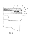
- Fig. 2 eine vergrößerte Teildarstellung einer Seitenansicht des Randbereichs der Einfüllöffnung,
- Fig. 3 eine Teildarstellung eines Axialschnitts durch den Deckel,
- Fig. 4 eine Teildarstellung des Behälters mit aufgesetztem Deckel,
- Fig. 5A, 5B, Detaildarstellung der rampenartigen Vorsprünge des Drehverschlusses,
- Fig. 6 eine weitere Darstellung eines Axialschnitts durch den Deckel.
- 1 is a partial representation of a side view of the disposable container according to the invention with a lid,
- 2 is an enlarged partial view of a side view of the edge region of the filling opening,
- 3 is a partial representation of an axial section through the cover,
- 4 is a partial view of the container with the lid attached,
- 5A, 5B, detailed representation of the ramp-like projections of the twist lock,
- Fig. 6 shows a further illustration of an axial section through the cover.
In Fig. 1 ist ein Einwegbehälter 1 mit einem Deckel 2 dargestellt. Der Deckel besitzt einen radial abstehenden Handgriff 20 und an seiner vertieften Oberseite einen weiteren Handgriff 26. Am Behälter sind sich diametral gegenüberliegend Griffe 25 ausgeformt. Der in Fig. 1. dargestellte Behälter hat ein Volumen von etwa 30 Liter Die Erfindung ist jedoch auch auf Behälter mit einem höheren Volumeninhalt, z.B. 60 Liter anwendbar.In Fig. 1, a
In der in Fig. 2 gezeigten Darstellung ist mit dem Bezugszeichen 4 die Einfüllöffnung gekennzeichnet. Im Randbereich 4 unterhalb der Einfüllöffnung 4 ist eine umlaufende Nut 9 angeformt. Die Nut ist derart ausgebildet, daß der behälterseitige Abschnitt 9ʹ radial weiter nach außen vortritt, als der zur Einfüllöffnung nach oben gerichtete Abschnitt 9ʺ. Durch diese besondere Ausführung erhält man eine zusätzliche Abstützung für den Dichtungsring 10, der in die Nut eingesetzt ist. Der Dichtungsring wirkt mit einer Gegenfläche 5 zusammen, die an entsprechender Stelle am Deckel 2 ausgebildet ist. Diese Gegenfläche 11 ist im vorliegenden Ausführungsbeispiel als Schrägfläche ausgebildet. Beim Schließen des Deckels kommt diese Schrägfläche zur Anlage gegen den Dichtungsring 10 und drückt mit einer im wesentlichen schräg zur Achse des Behälters nach unten gerichteten Kraftkomponente den Dichtungsring 10 in die Dichtungsnut 9. (Vergl. Fig.4).In the illustration shown in FIG. 2, the filling opening is identified by
Unterhalb der in Fig. 4 insgesamt mit der Bezugsziffer 5 gekennzeichneten Dichtung ist ein Drehverschluß 14 ausgebildet. Dieser Drehverschluß 14 besteht aus zum einen am Behälter angeordneten rampenartigen Vorsprüngen 14A mit einer nach unten gerichteten Rampenfläche 15 und zum anderen aus am Deckel an entsprechender Stelle angeformten passend dazu ausgebildeten Vorsprüngen 14B mit nach oben gerichteten Rampenflächen 16. Diese Vorsprünge treten beim Verdrehen des Deckels nach Art von Gewindeflanken gegenseitig in Eingriff und erzeugen eine axial gerichtete Kraft, die zu einer Pressung der Dichtung 5 führt. Die Steigung der Rampenflächen 15, 16 ist dabei derart gewählt, daß ein Überdrehen des Verschlusses nicht möglich ist. Um dieser Gefahr zu begegnen, kann auch am entsprechenden Ende einer Rampenfläche eines Vorsprungs 16 oder eines Vorsprungs 15 eine Anschlagfläche vorgesehen sein, (nicht dargestellt).A
Am freien Ende des axial zum Behälter gerichteten Deckelrands 3 ist nach Art eines Hakens eine Einrastkante 7 mit einer schrägen Gleitfläche 17 ausgebildet. Diese Einrastkante 7 hintergreift beim endgültigen Verschließen des Behälters einen unmittelbar am Außenumfang der Seitenwand des Behälters angeformten Haltevorsprung 8, wobei ein erhöhter Kraftaufwand erforderlich ist, damit die Einrastkante 7 durch Überspringen des Haltevorsprungs 8 in die Verschlußstellung gebracht werden kann. Dieser Kraftaufwand dient zum einen zum Zusammenpressen der Dichtung und zum anderen dem elastischen Aufweiten des freien Rands des Deckels 3, der, nachdem die Einrastkante 7 den Haltevorsprung 8 am Deckel übersprungen hat, in seine ursprüngliche Stellung zurückkehrt.Das Überspringen wird erleichtert durch eine Gleitfläche 18, die beim Aufdrücken des Deckels auf den Behälter mit der Gleitfläche 17 am Einrastvorsprung zusammenwirkt.At the free end of the
Dieser Verschluß ist ohne zerstörende Gewaltanwendung nicht wieder zu lösen. Eine weitere Erschwernis kann dadurch hergestellt werden, daß die Gleitfläche 17 nicht als eine Schrägfläche, sondern als eine parallel zur Wand unterhalb des Haltevorsprungs 8 ausgebildete Fläche ist, so daß eine nahezu hermetische und spaltenfreie Verriegelung erzielt wird (nicht dargestellt).This closure cannot be released again without the use of destructive force. A further difficulty can be created by the fact that the
An der Deckelunterseite ist eine umlaufende Nut 21 ausgebildet, in die der freie Rand 22 der Einfüllöffnung 4 eintreten kann. Die radial innenliegende Nutwand 23 der Innennut 21 ist so weit heruntergezogen, daß sie sich bis zur Höhe der gegenüberliegenden Schrägfläche 11 erstreckt, welche letztere sich an die radial außenliegende Nutwand 23ʹ nach unten anschließt. Die innenliegende Nutwand 23 ist mittels Stützrippen 24 abgestützt, wobei diese Stützrippen 24 gleichzeitig die Stabilisierung einer auf der Deckeloberfläche umlaufenden Stapelnut 19 sicherstellen.A
Durch die Anlage der radial innenliegenden Nutenwand 23 an der radial nach innen vortretenden Wand der Dichtungsnut 9 wird einerseits eine Abstützung für die Dichtung 5 und andererseits eine selbständige weitere Abdichtung bereitsgestellt. In Fig. 6 ist ein weiteres Detail des Deckels dargestellt. Zumindest an vier, regelmäßig im Abstand auf dem Umfang verteilten Abstützrippen 24 sind axiale Vorsprünge 27 ausgebildet, die einer Zentrierung des Deckels auf der Einfüllöffnung 4 dienen.The contact of the radially
Bei einer nicht dargestellten Ausführungsvariante kann vorgesehen sein, daß die Schrägfläche als eine gekrümmte, an einen Dichtungsring mehr oder weniger formgetreu angepaßte konkave Fläche ausgebildet ist.In an embodiment variant not shown, it can be provided that the inclined surface is designed as a curved concave surface which is more or less true to shape adapted to a sealing ring.
Claims (10)
Applications Claiming Priority (2)
| Application Number | Priority Date | Filing Date | Title |
|---|---|---|---|
| DE3700683A DE3700683C1 (en) | 1987-01-12 | 1987-01-12 | Closure arrangement for disposable containers |
| DE3700683 | 1987-01-12 |
Publications (2)
| Publication Number | Publication Date |
|---|---|
| EP0274706A2 true EP0274706A2 (en) | 1988-07-20 |
| EP0274706A3 EP0274706A3 (en) | 1989-03-29 |
Family
ID=6318707
Family Applications (1)
| Application Number | Title | Priority Date | Filing Date |
|---|---|---|---|
| EP87118780A Withdrawn EP0274706A3 (en) | 1987-01-12 | 1987-12-17 | Disposable container |
Country Status (4)
| Country | Link |
|---|---|
| US (1) | US4877150A (en) |
| EP (1) | EP0274706A3 (en) |
| CA (1) | CA1299549C (en) |
| DE (1) | DE3700683C1 (en) |
Cited By (2)
| Publication number | Priority date | Publication date | Assignee | Title |
|---|---|---|---|---|
| FR2700524A1 (en) * | 1993-01-18 | 1994-07-22 | Ilidio Do Livramento Rufino | Container for toxic waste products |
| WO2012038314A1 (en) | 2010-09-20 | 2012-03-29 | Aesculap Ag | Sterile container |
Families Citing this family (22)
| Publication number | Priority date | Publication date | Assignee | Title |
|---|---|---|---|---|
| DE3933177A1 (en) * | 1989-10-04 | 1991-04-11 | Hermedicon Wolfgang Herdlicka | PLASTIC CONTAINER FOR THE DISPOSAL OF DISPOSABLE MEDICAL OBJECTS AND DEVICES |
| US5031768A (en) * | 1990-04-09 | 1991-07-16 | Ultradent Products, Inc. | Instrument tray and disposable receptacle having alternative locking means |
| ATE135983T1 (en) * | 1990-05-09 | 1996-04-15 | Deroyal Ind Inc | METHOD FOR DELIVERY, STORAGE AND DISPOSAL OF MEDICAL CONSUMABLES |
| US5235795A (en) * | 1990-05-09 | 1993-08-17 | Deroyal Industries, Inc. | System for the delivery, storage and disposal of medical supplies |
| US5163576A (en) * | 1991-06-21 | 1992-11-17 | Galer Herbert W | Lid and container assembly incorporating camming lid application structure |
| WO1996009228A1 (en) * | 1993-03-29 | 1996-03-28 | Custom Medical Plastics, Inc. | Fluid tight medical apparatus disposal receptacle |
| US5447245A (en) * | 1993-07-20 | 1995-09-05 | Merhar; Richard D. | Graduated proportioning and mixing container |
| US5419435A (en) * | 1994-06-08 | 1995-05-30 | Medx, Inc. | Sharps disposal system including reusable container |
| US5494158A (en) * | 1994-12-29 | 1996-02-27 | Mmct Holdings, Llc | Syringe sales and disposal box |
| CH696932A5 (en) * | 2003-10-01 | 2008-02-15 | Walter Brauchli | Container. |
| CO5700164A1 (en) * | 2005-07-13 | 2006-11-30 | Chaparro Mario Valderrama | COVER FOR FOOD AND BEVERAGE PROTECTION |
| US20080073359A1 (en) * | 2006-09-22 | 2008-03-27 | Fontaine James R | Sealing structure for a tank which is closed by a cap |
| US20080179207A1 (en) * | 2007-01-29 | 2008-07-31 | Medport, Llc | Sharps disposal container with locking cover |
| US20090236347A1 (en) * | 2008-03-19 | 2009-09-24 | Ultimed Inc. | Sharps container |
| US20110272297A1 (en) | 2010-05-10 | 2011-11-10 | Mallinckrodt Inc. | Pharmaceutical product container with permanent locking mechanism |
| US9340330B2 (en) | 2010-06-24 | 2016-05-17 | S. C. Johnson & Son, Inc. | Storage container lids |
| CO6350189A1 (en) * | 2011-04-13 | 2011-12-20 | Pablo Poch Figueroa | POLIFORM CONTAINER FOR THE DEPOSIT OF PATHOGENIC, BIOLOGICAL, BIOSANITARY, ANAPATOLOGICAL AND HOSPITAL WASTE WITH HERMETIC CLOSURE. |
| US8863975B2 (en) * | 2011-12-02 | 2014-10-21 | Rehrig Pacific Company | Waste container |
| IN2014DN09047A (en) * | 2012-04-09 | 2015-05-22 | Akooba Inc | |
| DE202012103382U1 (en) | 2012-06-08 | 2013-09-10 | Rpc Bramlage Gmbh | container |
| CN106144177B (en) * | 2015-04-17 | 2018-10-23 | 江苏健龙电器有限公司 | A kind of band presets the high protective plastic case of mounting hole |
| US10321968B2 (en) | 2015-10-23 | 2019-06-18 | Medline Industries, Inc. | Sharps container |
Citations (5)
| Publication number | Priority date | Publication date | Assignee | Title |
|---|---|---|---|---|
| GB331533A (en) * | 1929-04-02 | 1930-07-02 | Eric Leslie Furber | Improvements in or relating to bottles, jars and the like containers, and in covers, closure means and moisture-absorbing devices therefor |
| GB644612A (en) * | 1947-10-14 | 1950-10-11 | Jackson Brothers Of Knottingle | Improvements in closures for jars and like containers |
| DE1432139A1 (en) * | 1964-04-07 | 1968-12-12 | Continental Can Co | Closure on plastic containers |
| DE2407841A1 (en) * | 1974-02-19 | 1975-08-21 | Schwartauer Werke Gmbh & Co | Container with round plastics lid - has positive locking devices below ramp faces on neck and lid |
| DE3436399C2 (en) * | 1984-10-04 | 1988-06-16 | Willem Jan Veenendaal Nl Achterberg |
Family Cites Families (9)
| Publication number | Priority date | Publication date | Assignee | Title |
|---|---|---|---|---|
| DE2544244A1 (en) * | 1975-10-03 | 1977-04-14 | Mauser Kg | PLASTIC CONTAINER WITH SEALABLE LID |
| DE2551820A1 (en) * | 1975-11-19 | 1977-06-02 | Heinz Konen | STORAGE AND TRANSPORT CONTAINERS, IN PARTICULAR CASES, MADE OF TOAEHELASTIC MATERIAL |
| US4371092A (en) * | 1981-10-29 | 1983-02-01 | Teague Lyndon M | Waste container with permanent lid hold-down assemblies |
| US4552280A (en) * | 1981-11-26 | 1985-11-12 | Owen William R | Containers for waste products |
| US4488643A (en) * | 1983-10-28 | 1984-12-18 | Bemis Manufacturing Company | Syringe and needle disposal system |
| US4520926A (en) * | 1984-02-27 | 1985-06-04 | Winfield Corp. | Container for sharps |
| US4657139A (en) * | 1985-09-30 | 1987-04-14 | Sage Products, Inc. | Closure for a syringe collection and disposal container |
| US4609125A (en) * | 1985-11-20 | 1986-09-02 | General Fabricators, Inc. | Waste material container and closure fastening means |
| US4715498A (en) * | 1986-11-24 | 1987-12-29 | Sage Products, Inc. | Sharps disposal system |
-
1987
- 1987-01-12 DE DE3700683A patent/DE3700683C1/en not_active Expired
- 1987-12-17 EP EP87118780A patent/EP0274706A3/en not_active Withdrawn
- 1987-12-28 US US07/138,444 patent/US4877150A/en not_active Expired - Lifetime
-
1988
- 1988-01-08 CA CA000556133A patent/CA1299549C/en not_active Expired - Lifetime
Patent Citations (5)
| Publication number | Priority date | Publication date | Assignee | Title |
|---|---|---|---|---|
| GB331533A (en) * | 1929-04-02 | 1930-07-02 | Eric Leslie Furber | Improvements in or relating to bottles, jars and the like containers, and in covers, closure means and moisture-absorbing devices therefor |
| GB644612A (en) * | 1947-10-14 | 1950-10-11 | Jackson Brothers Of Knottingle | Improvements in closures for jars and like containers |
| DE1432139A1 (en) * | 1964-04-07 | 1968-12-12 | Continental Can Co | Closure on plastic containers |
| DE2407841A1 (en) * | 1974-02-19 | 1975-08-21 | Schwartauer Werke Gmbh & Co | Container with round plastics lid - has positive locking devices below ramp faces on neck and lid |
| DE3436399C2 (en) * | 1984-10-04 | 1988-06-16 | Willem Jan Veenendaal Nl Achterberg |
Cited By (3)
| Publication number | Priority date | Publication date | Assignee | Title |
|---|---|---|---|---|
| FR2700524A1 (en) * | 1993-01-18 | 1994-07-22 | Ilidio Do Livramento Rufino | Container for toxic waste products |
| WO2012038314A1 (en) | 2010-09-20 | 2012-03-29 | Aesculap Ag | Sterile container |
| EP3192532A1 (en) | 2010-09-20 | 2017-07-19 | Aesculap AG | Sterile container |
Also Published As
| Publication number | Publication date |
|---|---|
| US4877150A (en) | 1989-10-31 |
| CA1299549C (en) | 1992-04-28 |
| EP0274706A3 (en) | 1989-03-29 |
| DE3700683C1 (en) | 1988-01-07 |
Similar Documents
| Publication | Publication Date | Title |
|---|---|---|
| DE3700683C1 (en) | Closure arrangement for disposable containers | |
| EP0520207B1 (en) | Bottle closure for two-compartment containers | |
| EP0235806B1 (en) | Bottle sealing cap for two component containers | |
| DE3411920A1 (en) | Airtightly sealable container | |
| DE2529340B2 (en) | Container with a screw cap and method of putting the screw cap on | |
| DE2807791A1 (en) | CONTAINER LID ARRANGEMENT | |
| DE2921628A1 (en) | CONTAINER LID ARRANGEMENT | |
| EP0133520A2 (en) | Container closure with venting means | |
| DE7226163U (en) | Safety cap | |
| EP0421410A2 (en) | Plastic container for the removal of disposable medical items and devices | |
| EP0675051B1 (en) | Threaded cap with a welded ring | |
| DE1657139B2 (en) | Closure cap for hermetically sealing a container | |
| DE2000413B2 (en) | Container lock | |
| EP0455172B1 (en) | One-time use collection and transport container | |
| DE19807768A1 (en) | Closure for bucket or tub-shaped plastic container has inwards directed | |
| DE102009011528A1 (en) | Sterilization container for sterilizing medical and surgical instruments, has lower part and upper part connected with each other in sealed manner, where upper part and lower part are formed like tub and have side walls extending from base | |
| WO2011141376A1 (en) | Closure for a receptacle and method for carrying out a freeze-drying process | |
| EP1010399B1 (en) | Container for medical waste sterilization | |
| EP0222324A2 (en) | Fust with a bung | |
| EP0569897A1 (en) | Child resistant device for closing containers | |
| EP0907577B1 (en) | Device for closure of containers | |
| DE69630471T2 (en) | TABLET STORAGE CONTAINERS | |
| DE102009011435A1 (en) | Grasping element for sterilization container, is connected with sterilization container in detachable manner, where grasping element comprises catch element, which is connected with lower part and upper part of sterilization container | |
| EP0701949B1 (en) | Child-proof container closure | |
| DE19505805A1 (en) | Product receptacle for flowable and / or pourable products |
Legal Events
| Date | Code | Title | Description |
|---|---|---|---|
| PUAI | Public reference made under article 153(3) epc to a published international application that has entered the european phase |
Free format text: ORIGINAL CODE: 0009012 |
|
| AK | Designated contracting states |
Kind code of ref document: A2 Designated state(s): AT BE CH ES FR GB GR IT LI LU NL SE |
|
| PUAL | Search report despatched |
Free format text: ORIGINAL CODE: 0009013 |
|
| AK | Designated contracting states |
Kind code of ref document: A3 Designated state(s): AT BE CH ES FR GB GR IT LI LU NL SE |
|
| 17P | Request for examination filed |
Effective date: 19890406 |
|
| 17Q | First examination report despatched |
Effective date: 19901130 |
|
| STAA | Information on the status of an ep patent application or granted ep patent |
Free format text: STATUS: THE APPLICATION HAS BEEN WITHDRAWN |
|
| 18W | Application withdrawn |
Withdrawal date: 19910719 |