EP0274295A1 - Method and apparatus for automatically assembling layered-glass panes - Google Patents
Method and apparatus for automatically assembling layered-glass panes Download PDFInfo
- Publication number
- EP0274295A1 EP0274295A1 EP87402676A EP87402676A EP0274295A1 EP 0274295 A1 EP0274295 A1 EP 0274295A1 EP 87402676 A EP87402676 A EP 87402676A EP 87402676 A EP87402676 A EP 87402676A EP 0274295 A1 EP0274295 A1 EP 0274295A1
- Authority
- EP
- European Patent Office
- Prior art keywords
- sheet
- centering
- primitive
- flexible
- transfer
- Prior art date
- Legal status (The legal status is an assumption and is not a legal conclusion. Google has not performed a legal analysis and makes no representation as to the accuracy of the status listed.)
- Granted
Links
Images


Classifications
-
- B—PERFORMING OPERATIONS; TRANSPORTING
- B32—LAYERED PRODUCTS
- B32B—LAYERED PRODUCTS, i.e. PRODUCTS BUILT-UP OF STRATA OF FLAT OR NON-FLAT, e.g. CELLULAR OR HONEYCOMB, FORM
- B32B17/00—Layered products essentially comprising sheet glass, or glass, slag, or like fibres
- B32B17/06—Layered products essentially comprising sheet glass, or glass, slag, or like fibres comprising glass as the main or only constituent of a layer, next to another layer of a specific material
- B32B17/10—Layered products essentially comprising sheet glass, or glass, slag, or like fibres comprising glass as the main or only constituent of a layer, next to another layer of a specific material of synthetic resin
-
- B—PERFORMING OPERATIONS; TRANSPORTING
- B65—CONVEYING; PACKING; STORING; HANDLING THIN OR FILAMENTARY MATERIAL
- B65H—HANDLING THIN OR FILAMENTARY MATERIAL, e.g. SHEETS, WEBS, CABLES
- B65H9/00—Registering, e.g. orientating, articles; Devices therefor
-
- B—PERFORMING OPERATIONS; TRANSPORTING
- B32—LAYERED PRODUCTS
- B32B—LAYERED PRODUCTS, i.e. PRODUCTS BUILT-UP OF STRATA OF FLAT OR NON-FLAT, e.g. CELLULAR OR HONEYCOMB, FORM
- B32B17/00—Layered products essentially comprising sheet glass, or glass, slag, or like fibres
- B32B17/06—Layered products essentially comprising sheet glass, or glass, slag, or like fibres comprising glass as the main or only constituent of a layer, next to another layer of a specific material
- B32B17/10—Layered products essentially comprising sheet glass, or glass, slag, or like fibres comprising glass as the main or only constituent of a layer, next to another layer of a specific material of synthetic resin
- B32B17/10005—Layered products essentially comprising sheet glass, or glass, slag, or like fibres comprising glass as the main or only constituent of a layer, next to another layer of a specific material of synthetic resin laminated safety glass or glazing
- B32B17/10807—Making laminated safety glass or glazing; Apparatus therefor
- B32B17/10899—Making laminated safety glass or glazing; Apparatus therefor by introducing interlayers of synthetic resin
- B32B17/10954—Making laminated safety glass or glazing; Apparatus therefor by introducing interlayers of synthetic resin by using an aligning laminating device
-
- B—PERFORMING OPERATIONS; TRANSPORTING
- B65—CONVEYING; PACKING; STORING; HANDLING THIN OR FILAMENTARY MATERIAL
- B65H—HANDLING THIN OR FILAMENTARY MATERIAL, e.g. SHEETS, WEBS, CABLES
- B65H9/00—Registering, e.g. orientating, articles; Devices therefor
- B65H9/16—Inclined tape, roller, or like article-forwarding side registers
-
- C—CHEMISTRY; METALLURGY
- C03—GLASS; MINERAL OR SLAG WOOL
- C03C—CHEMICAL COMPOSITION OF GLASSES, GLAZES OR VITREOUS ENAMELS; SURFACE TREATMENT OF GLASS; SURFACE TREATMENT OF FIBRES OR FILAMENTS MADE FROM GLASS, MINERALS OR SLAGS; JOINING GLASS TO GLASS OR OTHER MATERIALS
- C03C27/00—Joining pieces of glass to pieces of other inorganic material; Joining glass to glass other than by fusing
- C03C27/06—Joining glass to glass by processes other than fusing
- C03C27/10—Joining glass to glass by processes other than fusing with the aid of adhesive specially adapted for that purpose
-
- Y—GENERAL TAGGING OF NEW TECHNOLOGICAL DEVELOPMENTS; GENERAL TAGGING OF CROSS-SECTIONAL TECHNOLOGIES SPANNING OVER SEVERAL SECTIONS OF THE IPC; TECHNICAL SUBJECTS COVERED BY FORMER USPC CROSS-REFERENCE ART COLLECTIONS [XRACs] AND DIGESTS
- Y10—TECHNICAL SUBJECTS COVERED BY FORMER USPC
- Y10T—TECHNICAL SUBJECTS COVERED BY FORMER US CLASSIFICATION
- Y10T156/00—Adhesive bonding and miscellaneous chemical manufacture
- Y10T156/17—Surface bonding means and/or assemblymeans with work feeding or handling means
- Y10T156/1702—For plural parts or plural areas of single part
- Y10T156/1744—Means bringing discrete articles into assembled relationship
Definitions
- the present invention relates to the automatic manufacture of laminated structures such as laminated glazing.
- Laminated glazing used in buildings and in transport vehicles in particular as a windshield, generally consists of at least one rigid sheet such as a glass sheet or a sheet of plastic material such as polycarbonate or polymethacrylate. methyl, and at least one sheet of flexible plastic, polyvinyl butyral or polyurethane for example, generally used as an interlayer sheet in the case of a structure comprising two rigid sheets.
- the flexible plastic sheet or sheets are cut beforehand in the exact format of the glazing or generally in a slightly larger geometric format which is designated by primitive, they are stacked with the other constituent elements of the glazing. laminated and all these elements are assembled using an assembly operation proper generally carried out in two stages: a first stage consisting, for example, of a calendering operation providing a preliminary assembly, followed by a second stage consisting of an autoclave cycle using the temperature and pressure providing the final assembly.
- the invention relates more particularly to the stacking of the flexible sheet with the other constituent elements of the laminated glazing, and to the operations which are linked to it, in particular its prior centering in an intermediate position close to the stacking station, its transfer to the stacking station and its removal in the correct position in the stack.
- the invention provides a method of automatically assembling laminated glazing in which the position of each of the flexible sheets is adjusted separately in an intermediate position, which in particular eliminates any risk of shifting from one sheet to the other .
- the flexible sheet is brought to the stacking station from a horizontal and fixed gripping position, by a determined stroke transfer, the flexible sheet being previously positioned by gravity in at least one of the two coordinates from the horizontal plane, determining the gripping position.
- the flexible sheet is positioned in the chosen coordinate, by pressing against a longitudinal rule itself arranged in a previously chosen position.
- the positioning of the flexible sheet according to the other coordinate of the plane allowing its centering, can be achieved by a longitudinal displacement and passage in front of a detector.
- the plastic sheet is supported by an air cushion during the gravity positioning operation.
- each of the sheets of flexible plastic material in a determined intermediate position has several advantages.
- This individual focusing can also be applied to a primitive obtained directly after cutting it from a roller, without intermediate storage of the primitives. It applies to all types of more or less rigid polyvinyl butyral.
- the invention also relates to a device for implementing the method.
- the device for automatic assembly according to the invention comprises centering means for rigid sheets such as glass sheets, these means being arranged at the glazing stacking station, centering or focusing means in an intermediate position of the sheet of flexible plastic material, these means comprising a tilting table provided with a rule arranged according to one of the two coordinates determining the intermediate position, generally parallel to the tilting axis of the table, means for transferring the sheet of material flexible plastic from its intermediate centering position to the glazing stacking station, a conveyor bringing the rigid sheets to the stacking station, an auxiliary conveyor bringing the flexible sheets to the table for intermediate centering.
- FIG. 1 represents the transfer line from the primitive 1 between a double supply conveyor 2 and the stacking station 3 of the components of the laminated glazing to be manufactured 101, located in the line of the supply conveyor 102 for the glass sheets 8a, 8b, so-called assembly line, perpendicular to the transfer line of the primitive.
- the supply conveyor 2 perpendicular to the transfer line brings the primitive 1 of trapezoidal shape oriented after cutting with its bases arranged substantially parallel to the axis of the conveyor 2, to a pivot table 4 which rotates the primitive by 90 ° in the desired direction according to the initial orientation of the pitch on the conveyor 2, so that the large base of the trapezium is always on the same side, relative to the centering table 6.
- the pivot table is equipped with drive means 5, for example conveyor belts which transport the primitive from the supply conveyor 2 to the centering or focusing table 6.
- drive means 5 for example conveyor belts which transport the primitive from the supply conveyor 2 to the centering or focusing table 6.
- the movement of transfer from the pivot table 4 to the centering table 6 is facilitated by an air cushion with which the centering table 6 is equipped, as explained in more detail below.
- the sides 103, 104 of the pivot table are cut into convex arcs of a circle while the side 105 of the centering table facing it is cut along a concave arc, in order to facilitate the maneuvers of the pivot table 4 without having to move the centering table 6.
- the primitive 1 is centered according to the two centering coordinates, determined with respect to two perpendicular axes X, Y as shown in Figures 2 and 3.
- the primitive is entered by a transfer gripper 7 which transfers it to the stacking station 3 by a displacement of constant stroke, where it is deposited on the lower glass sheet 8a waiting at this station.
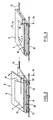
- FIGS. 4 and 5 schematically represent the centering of the primitive on the centering table 6 according to the two coordinates of the intermediate position determined with respect to the axes X and Y.
- the centering table 6 comprises an upper tilting plate 9 around hinges 10 arranged longitudinally on a lower plate 11 which slides on rails 12, 13 carried as shown in FIGS. 4, 5, 6, by an elevating structure 14 itself sliding vertically on a frame 15. Positioning according to the Y coordinate is achieved by tilting the upper plate 9 which causes the base of the primitive 1 to press against gravity against a rule 16 disposed on the tilting plate.
- Positioning according to the X coordinate is achieved by a displacement shown diagrammatically by the arrow x of the two plates 9, 11 along the rails 12, 13 until the edge of the inclined side 17 of the trapezoid intercepts the axis 18 of a detector 19, for example an optical detector such as a cell placed under the plate 11.
- Figures 4, 5 and 6 show a centering table 6 of the device according to the invention.
- the table 6 comprises a tilting upper plate 9 pivotally mounted on hinges 10 fixed along a longitudinal side of a lower plate 11, so that the upper plate 9 can tilt around an axis horizontal 20 parallel to the axis 21 of the transfer line.
- a rule 16 parallel to the axis 21 is supported on the surface 22 of the tilting plate 9.
- the two ends of the rule are fixed to the rods 23, 24 of two horizontal cylinders 25, 26 carried by the lifting structure 14, perpendicular to the 'axis of the table 6 which merges with the axis of the transfer line 21.
- These two jacks 25, 26 are capable of deviating the rule 16 of the plate 9 relative to the axis of the table in order to facilitate the subsequent gripping of the primitive 1 once positioned, by the transfer gripper 7.
- the position of the ruler on the board can be modified if necessary for other types of primitives.
- the tilting movement of the tilting plate is provided by a jack 27 with oscillating attachment 28, carried by the lower plate 11.
- This lower plate 11 is slidably mounted by means of bearings 29 on the rails 12, 13 supported by the lifting structure 14, itself vertically sliding mounted, by means of ball bushings 30, on the frame 15.
- the high position of the lifting structure 14 supporting the table 6 is used for gripping the primitive 1 from the table 6 by the transfer gripper 7, while the low position is used for centering the primitive.
- the up-down movement of the lifting structure 14 is controlled by the action of an electric motor 31 and of a transmission system 32 comprising chains, toothed wheels and vertical racks 33, integral with the lifting structure 14.
- the movement of the table 6 in a longitudinal movement along the rails 12, 13 is controlled by an electric motor 34 and a transmission system 35 which actuates the rotation of a screw 36, which causes the driving of a nut 37 integral with the table 6.
- the tilting plate 9 is pierced with orifices 38 connected to means (not shown) which can alternatively create an air cushion by blowing, or suction, according to the different phases of centering as explained below.
- the tilting plate 9 of the table 6 has a slot 39 which extends longitudinally over approximately half the length of the table.
- An optical detector 18 mounted via an arm 40 on the frame 15 under the table, in the vertical plane of the slot 39 can thus identify the passage of the inclined side 17 of the primitive in order to position the latter according to the second centering coordinate.
- the side 105 of the centering table 6 facing the pivot table is cut in a concave arc corresponding to the profile of the sides of the pivot table, which allows the pivoting of the pivot table without having to move to this the centering table.
- the device operates as follows.
- a primitive 1, of trapezoidal shape is brought by the supply conveyor 2 to the pivot table 4.
- the orientation of the primitive on the conveyor is such that the two bases of the trapezoid are substantially parallel to the axis of the conveyor 2.
- Transport belts 5 which equip the surface of the pivot table, drive the primitive on the centering table 6.
- the movement of passage from the pivot table 4 to the centering table 6 is favored by the air cushion created by blowing through the orifices 38 which is provided with the upper plate 9 of the table 6.
- the upper plate When the primitive is on the centering table 6, the upper plate is then tilted by the action of the jack 27, around the hinges 10.
- the primitive by gravity, is placed with the support of its large base against the rule 16 initially placed on the plate 9 in the desired position, parallel to the axis of the transfer line and in the desired coordinate relative to the Y axis.
- the blowing of air creating the air cushion is interrupted and it is replaced by a suction which is exerted by the same orifices 38 of the tilting plate, which keeps the pitch on the plate in the centering coordinate with respect to the axis Y.
- the plate re comes to the horizontal position and the assembly is driven by displacement of the table 6 along the rails 12, 13 along the axis of the transfer line until the passage of the inclined side 17 of the primitive directly above the axis 18 of the optical detector 19, the position of which corresponds to the desired coordinate with respect to the X axis.
- the primitive is then in the intermediate centering position also called the focusing position.
- the rule 9 is then released from the surface of the table 6, towards the outside, by the action of the two jacks 25, 26.
- the table 6 is then raised by the action of the electric motor 31 and the transmission system 32 with toothed wheels and racks, while the transfer gripper 7 arrives above it.
- the suction of the plate 9 of the table 6 is removed and it is again replaced by an air blowing while the transfer gripper exerts a suction.
- the primitive 1 passes from the upper plate 9 of the table 6 to the transfer gripper 7.
- the underside of the transfer gripper 7 is advantageously divided into several sections, for example five sections, controllable and adjustable separately for suction and blowing so as to facilitate in particular the subsequent removal of the primitive.
- the transfer gripper 7 then drives the primitive 1 by a displacement of constant stroke up to the stacking station where the lower glass sheet 8a is arranged horizontally, the glass sheet 8b being kept outside the space traversed by the transfer gripper 7.
- the suction of the transfer gripper 7 is then suppressed and the primitive then falls on the glass sheet 8a in the exact stacking position.
- the transfer gripper exerts a blowing, advantageously located in the center of the primitive 1.
- the upper glass sheet 8b is deposited on the primitive in order to complete stacking to form laminated glazing 101 which can then be driven to the next station.
- the next primitive is brought by the conveyor, then centered on the centering table 6.
Landscapes
- Chemical & Material Sciences (AREA)
- Engineering & Computer Science (AREA)
- Organic Chemistry (AREA)
- Life Sciences & Earth Sciences (AREA)
- Chemical Kinetics & Catalysis (AREA)
- General Chemical & Material Sciences (AREA)
- Geochemistry & Mineralogy (AREA)
- Materials Engineering (AREA)
- Ceramic Engineering (AREA)
- Joining Of Glass To Other Materials (AREA)
- Laminated Bodies (AREA)
- Glass Compositions (AREA)
- Magnetic Heads (AREA)
- Investigating Or Analysing Biological Materials (AREA)
- Cephalosporin Compounds (AREA)
- Turbine Rotor Nozzle Sealing (AREA)
- Containers And Plastic Fillers For Packaging (AREA)
Abstract
Description
La présente invention concerne la fabrication automatique de structures stratifiées telles des vitrages feuilletés.The present invention relates to the automatic manufacture of laminated structures such as laminated glazing.
Les vitrages feuilletés utilisés dans le bâtiment et dans les véhicules de transport, notamment en tant que pare-brise, sont formés généralement d'au moins une feuille rigide telle une feuille de verre ou une feuille de matière plastique comme le polycarbonate ou le polyméthacrylate de méthyle, et d'au moins une feuille en matière plastique souple, en polyvinylbutyral ou en polyuréthane par exemple, utilisée généralement comme feuille intercalaire dans le cas d'une structure comprenant deux feuilles rigides.Laminated glazing used in buildings and in transport vehicles, in particular as a windshield, generally consists of at least one rigid sheet such as a glass sheet or a sheet of plastic material such as polycarbonate or polymethacrylate. methyl, and at least one sheet of flexible plastic, polyvinyl butyral or polyurethane for example, generally used as an interlayer sheet in the case of a structure comprising two rigid sheets.
Pour fabriquer ces vitrages feuilletés, on découpe la ou les feuilles de matière plastique souple au préalable au format exact du vitrage ou généralement à un format géométrique légèrement plus grand que l'on désigne par primitif, on les empile avec les autres éléments constitutifs du vitrage feuilleté et on assemble tous ces éléments à l'aide d'une opération d'assemblage proprement dite généralement effectuée en deux étapes : une première étape consistant, par exemple, en une opération de calandrage fournissant un assemblage préliminaire, suivie d'une seconde étape consistant en un cycle d'autoclave mettant en oeuvre la température et la pression fournissant l'assemblage définitif.To manufacture these laminated glazings, the flexible plastic sheet or sheets are cut beforehand in the exact format of the glazing or generally in a slightly larger geometric format which is designated by primitive, they are stacked with the other constituent elements of the glazing. laminated and all these elements are assembled using an assembly operation proper generally carried out in two stages: a first stage consisting, for example, of a calendering operation providing a preliminary assembly, followed by a second stage consisting of an autoclave cycle using the temperature and pressure providing the final assembly.
L'invention concerne plus particulièrement l'empilage de la feuille souple avec les autres éléments constitutifs du vitrage feuilleté, et les opérations qui lui sont liées, notamment son centrage préalable dans une position intermédiaire voisine du poste d'empilage, son transfert au poste d'empilage et sa dépose en position correcte dans l'empilage.The invention relates more particularly to the stacking of the flexible sheet with the other constituent elements of the laminated glazing, and to the operations which are linked to it, in particular its prior centering in an intermediate position close to the stacking station, its transfer to the stacking station and its removal in the correct position in the stack.
Un des problèmes rencontrés dans l'automatisation des différentes opérations utilisées pour la fabrication des vitrages feuilletés est le positionnement correct de la feuille de matière plastique souple dans l'empilage pour former le vitrage.One of the problems encountered in the automation of the various operations used for the manufacture of laminated glazing is the correct positioning of the sheet of flexible plastic material in the stack to form the glazing.
Une solution déjà proposée consiste à disposer les feuilles de matière plastique les unes sur les autres de façon précise à un emplacement fixe et déterminé appelé poste de stockage. Dans ce cas on saisit la feuille en cet emplacement et on la transfère par une course de longueur constante jusqu'au poste d'empilage du vitrage feuilleté. Malheureusement, les feuilles de matière plastique en polyvinylbutyral ou en polyuréthane présentent à la température ambiante des ateliers d'assemblage une certaine prétension à coller entre elles et il est courant qu'au moment de la préhension de la feuille supérieure de la pile on saisisse du même coup temporairement la feuille sous-jacente qui lui est plus ou moins collée ce qui peut décaler cette deuxième feuille de sa position correcte de préhension. Le décalage de la feuille qui en résulte est ensuite transféré au poste d'empilage, et finalement, l'empilement ne sera pas correct.One solution already proposed consists in placing the plastic sheets on top of each other in a precise manner at a fixed and determined location called a storage station. In this case, the sheet is gripped at this location and transferred by a stroke of constant length to the stacking station for the laminated glazing. Unfortunately, polyvinyl butyral or polyurethane plastic sheets have a certain pretension to stick together at room temperature in assembly workshops and it is common that when gripping the upper sheet of the stack, same blow temporarily the underlying sheet which is more or less stuck to it which can shift this second sheet from its correct gripping position. The resulting sheet offset is then transferred to the stacking station, and finally, the stacking will not be correct.
L'invention propose un procédé d'assemblage automatique du vitrage feuilleté dans lequel on règle la position de chacune des feuilles souples, séparément, dans une position intermédiaire, ce qui, notamment, élimine tout risque de décalage d'une feuille à l'autre.The invention provides a method of automatically assembling laminated glazing in which the position of each of the flexible sheets is adjusted separately in an intermediate position, which in particular eliminates any risk of shifting from one sheet to the other .
Selon l'invention, la feuille souple est amenée au poste d'empilage à partir d'une position de préhension horizontale et fixe, par un transfert de course déterminée, la feuille souple étant au préalable positionnée par gravité dans au moins une des deux coordonnées du plan horizontal, déterminant la position de préhension.According to the invention, the flexible sheet is brought to the stacking station from a horizontal and fixed gripping position, by a determined stroke transfer, the flexible sheet being previously positioned by gravity in at least one of the two coordinates from the horizontal plane, determining the gripping position.
Selon une caractéristique du procédé, la feuille souple est positionnée dans la coordonnée choisie, par appui contre une règle longitudinale disposée elle-même dans une position choisie au préalable.According to a characteristic of the process, the flexible sheet is positioned in the chosen coordinate, by pressing against a longitudinal rule itself arranged in a previously chosen position.
Le positionnement de la feuille souple selon l'autre coordonnée du plan permettant son centrage, peut étre réalisé par un déplacement longitudinal et passage devant un détecteur.The positioning of the flexible sheet according to the other coordinate of the plane allowing its centering, can be achieved by a longitudinal displacement and passage in front of a detector.
Pour faciliter les opérations de positionnement, c'est-à-dire de focalisation, dans la position désirée intermédiaire, avantageusement la feuille de matière plastique est supportée par un coussin d'air au cours de l'opération de positionnement par gravité.To facilitate positioning operations, that is to say focusing operations, in the desired intermediate position, advantageously the plastic sheet is supported by an air cushion during the gravity positioning operation.
Le positionnement individuel, c'est-à-dire la focalisation, de chacune des feuilles de matière plastique souple dans une position intermédiaire déterminée présente plusieurs avantages.The individual positioning, that is to say the focusing, of each of the sheets of flexible plastic material in a determined intermediate position has several advantages.
Ainsi, il ne nécessite pas un empilage précis des primitifs à un poste de préhension, et il évite tout problème de collage des feuilles entre elles.Thus, it does not require precise stacking of the primitives at a gripping station, and it avoids any problem of sticking of the sheets together.
En outre, la focalisation individuelle autorise des différences d'orientation des feuilles amenées par le convoyeur d'alimentation.In addition, individual focusing allows differences in orientation of the sheets fed by the feed conveyor.
Cette focalisation individuelle peut encore s'appliquer à un primitif obtenu directement après sa découpe à partir d'un rouleau, sans stockage intermédiaire des primitifs. Il s'applique à tous les types de polyvinylbutyral plus ou moins rigides.This individual focusing can also be applied to a primitive obtained directly after cutting it from a roller, without intermediate storage of the primitives. It applies to all types of more or less rigid polyvinyl butyral.
L'invention concerne aussi un dispositif pour la mise en oeuvre du procédé. Le dispositif pour l'assemblage automatique selon l'invention comprend des moyens de centrage pour les feuilles rigides telles les feuilles de verre, ces moyens étant disposés au poste d'empilage du vitrage, des moyens de centrage ou focalisation dans une position intermédiaire de la feuille de matière plastique souple, ces moyens comprenant une table basculante munie d'une règle disposée selon une des deux coordonnées déterminant la position intermédiaire, généralement parallèlement à l'axe de basculement de la table, des moyens pour le transfert de la feuille de matière plastique souple de sa position de centrage intermédiaire au poste d'empilage du vitrage, un convoyeur amenant les feuilles rigides au poste d'empilage, un convoyeur annexe amenant les feuilles souples à la table pour le centrage intermédiaire.The invention also relates to a device for implementing the method. The device for automatic assembly according to the invention comprises centering means for rigid sheets such as glass sheets, these means being arranged at the glazing stacking station, centering or focusing means in an intermediate position of the sheet of flexible plastic material, these means comprising a tilting table provided with a rule arranged according to one of the two coordinates determining the intermediate position, generally parallel to the tilting axis of the table, means for transferring the sheet of material flexible plastic from its intermediate centering position to the glazing stacking station, a conveyor bringing the rigid sheets to the stacking station, an auxiliary conveyor bringing the flexible sheets to the table for intermediate centering.
D'autres caractéristiques et avantages apparaitront dans la description suivante d'un dispositif selon l'invention.
- La figure 1 représente shématiquement la ligne de transfert du primitif entre le convoyeur d'approvisionnement et le poste d'empilage avec passage sur une table de centrage pour le centrage du primitif dans une position intermédiaire.
- Les figures 2 et 3 représentent schématiquement les étapes du centrage du primitif dans la position intermédiaire.
- La figure 4 représente une vue de dessus d'une table de centrage.
- La figure 5 est une vue en élévation de la table de centrage de la figure 4.
- La figure 6 est une vue de côté de la table représentée sur la figure 5.
- Figure 1 shows schematically the transfer line of the primitive between the supply conveyor and the stacking station with passage over a centering table for centering the primitive in an intermediate position.
- Figures 2 and 3 schematically show the steps of centering the primitive in the intermediate position.
- Figure 4 shows a top view of a centering table.
- FIG. 5 is an elevation view of the centering table of FIG. 4.
- Figure 6 is a side view of the table shown on Figure 5.
La figure 1 représente la ligne de transfert du primitif 1 entre un double convoyeur d'approvisionnement 2 et le poste d'empilage 3 des éléments constitutifs du vitrage feuilleté à fabriquer 101, situé dans la ligne du convoyeur d'amenée 102 des feuilles de verre 8a, 8b, ligne dite d'assemblage, perpendiculaire à la ligne de transfert du primitif. Le convoyeur d'approvisionnement 2 perpendiculaire à la ligne de transfert amène le primitif 1 de forme trapézoïdal orienté après la découpe avec ses bases disposées sensiblement parallèles à l'axe du convoyeur 2, à une table de pivotement 4 qui fait pivoter le primitif de 90° dans le sens désiré selon l'orientation initiale du primitif sur le convoyeur 2, de façon à ce que la grande base du trapèze se présente toujours du même côté, par rapport à la table de centrage 6. La table de pivotement est équipée de moyens d'entrainement 5, par exemple des bandes de transport qui transportent le primitif du convoyeur d'approvisionnement 2 à la table de centrage ou focalisation 6. Le mouvement de transfert de la table de pivotement 4 à la table de centrage 6 est facilité par un coussin d'air dont est équipé la table de centrage 6 comme expliqué plus en détail par la suite. Les côtés 103, 104 de la table de pivotement sont découpés en arcs de cercle convexes alors que le côté 105 de la table de centrage lui faisant face est découpé suivant un arc de cercle concave, ceci afin de faciliter les manoeuvres de la table de pivotement 4 sans avoir à déplacer pour autant la table de centrage 6.FIG. 1 represents the transfer line from the primitive 1 between a
Arrivé sur la table de centrage, le primitif 1 est centré selon les deux coordonnées de centrage, déterminées par rapport à deux axes perpendiculaires X, Y comme représenté sur les figures 2 et 3. Après le centrage dans la position intermédiaire, le primitif est saisi par un préhenseur de transfert 7 qui le transfère au poste d'empilage 3 par un déplacement de course constante, où il est déposé sur la feuille de verre inférieure 8a en attente à ce poste.Arrived on the centering table, the primitive 1 is centered according to the two centering coordinates, determined with respect to two perpendicular axes X, Y as shown in Figures 2 and 3. After centering in the intermediate position, the primitive is entered by a
Les figures 2 et 3 représentent schématiquement le centrage du primitif sur la table de centrage 6 selon les deux coordonnées de la position intermédiaire déterminée par rapport aux axes X et Y. La table de centrage 6 comprend un plateau supérieur basculant 9 autour de charnières 10 disposées longitudinalement sur un plateau inférieur 11 qui coulisse sur des rails 12, 13 portés comme représentés sur les figures 4, 5, 6, par une structure élévatrice 14 elle-même coulissante verticalement sur un bâti 15. Le positionnement selon la coordonnée Y est réalisé par un basculement du plateau supérieur 9 qui provoque la mise en appui par gravité de la base du primitif 1 contre une règle 16 disposée sur la plateau basculant. Le positionnement selon la coordonnée X est réalisé par un déplacement schématisé par la flèche x des deux plateaux 9, 11 le long des rails 12, 13 jusqu'à ce que le bord du côté incliné 17 du trapèze intercepte l'axe 18 d'un détecteur 19, par exemple un détecteur optique tel une cellule disposée sous le plateau 11.Figures 2 and 3 schematically represent the centering of the primitive on the centering table 6 according to the two coordinates of the intermediate position determined with respect to the axes X and Y. The centering table 6 comprises an
Les figures 4, 5 et 6 représentent une table de centrage 6 du dispositif selon l'invention. Comme décrit précédemment, la table 6 comprend un plateau supérieur basculant 9 monté pivotant sur des charnières 10 fixées le long d'un côté longitudinal d'un plateau inférieur 11, de façon à ce que le plateau supérieur 9 puisse basculer autour d'un axe horizontal 20 parallèle à l'axe 21 de la ligne de transfert.Figures 4, 5 and 6 show a centering table 6 of the device according to the invention. As described above, the table 6 comprises a tilting
Une règle 16 parallèle à l'axe 21 prend appui sur la surface 22 du plateau basculant 9. Les deux extrémités de la règle sont fixées aux tiges 23, 24 de deux vérins horizontaux 25, 26 portés par la structure élévatrice 14, perpendiculaires à l'axe de la table 6 qui se confond avec l'axe de la ligne de transfert 21. Ces deux vérins 25, 26 sont susceptibles d'écarter la règle 16 du plateau 9 par rapport à l'axe de la table afin de faciliter la préhension ultérieure du primitif 1 une fois positionné, par le préhenseur de transfert 7.A
La position de la règle sur la plateau peut le cas échéant étre modifiée pour d'autres types de primitifs. Le mouvement de basculement du plateau basculant est procuré par un vérin 27 à attache oscillante 28, porté par le plateau inférieur 11. Ce plateau inférieur 11 est monté coulissant par l'intermédiaire de paliers 29 sur les rails 12, 13 supportés par la structure élévatrice 14, elle-même montée coulissante verticalement, par l'intermédiaire de douilles à billes 30, sur le bâti 15. La position haute de la structure élévatrice 14 supportant la table 6 est utilisée pour la préhension du primitif 1 à partir de la table 6 par le préhenseur de transfert 7, alors que la position basse est utilisée pour le centrage du primitif.The position of the ruler on the board can be modified if necessary for other types of primitives. The tilting movement of the tilting plate is provided by a
Le mouvement de montée-baisse de la structure élévatrice 14 est commandé par l'action d'un moteur électrique 31 et d'un système de transmission 32 comprenant chaines, roues dentées et crémaillères verticales 33, solidaires de la structure élévatrice 14. Le mouvement de la table 6 selon un déplacement longitudinal le long des rails 12, 13 est commandé par un moteur électrique 34 et un système de transmission 35 qui actionne la rotation d'une vis 36, ce qui provoque l'entrainement d'un écrou 37 solidaire de la table 6.The up-down movement of the
Le plateau basculant 9 est percé d'orifices 38 reliés à des moyens (non représentés) qui peuvent alternativement créer un coussin d'air par soufflage, ou une aspiration, selon les différentes phases du centrage comme expliqué par la suite. Le plateau basculant 9 de la table 6 présente une fente 39 qui s'étend longitudinalement sur approximativement la moitié de la longueur de la table. Un détecteur optique 18 monté par l'intermédiaire d'un bras 40 sur le bâti 15 sous la table, dans le plan vertical de la fente 39 peut ainsi repérer le passage du côté incliné 17 du primitif afin de positionner celui-ci selon la deuxième coordonnée du centrage.The
Le côté 105 de la table de centrage 6 faisant face à la table de pivotement est découpé suivant un arc de cercle concave correspondant au profil des côtés de la table de pivotement, ce qui permet le pivotement de la table de pivotement sans avoir à déplacer pour cela la table de centrage.The
Le dispositif fonctionne de la manière suivante.The device operates as follows.
Un primitif 1, de forme trapézoïdal est amené par le convoyeur d'approvisionnement 2 à la table de pivotement 4. L'orientation du primitif sur le convoyeur est telle que les deux bases du trapèze sont sensiblement parallèles à l'axe du convoyeur 2. Dès qu'il est sur la table de pivotement 4, celle-ci pivote dans le sens permettant de présenter la grande base du trapèze face à la règle 16 lorsque le primitif arrivera sur la table de centrage 6. Des courroies de transport 5 qui équipent la surface de la table de pivotement, entrainent le primitif sur la table de centrage 6. Le mouvement de passage de la table de pivotement 4 à la table de centrage 6 est favorisé par le coussin d'air créé par soufflage à travers les orifices 38 dont est pourvu le plateau supérieur 9 de la table 6. Lorsque le primitif est sur la table de centrage 6, le plateau supérieur est alors basculé par l'action du vérin 27, autour des charnières 10. Le primitif, par gravité, se place avec appui de sa grande base contre la règle 16 disposée initialement sur le plateau 9 dans la position désirée, parallèle à l'axe de la ligne de transfert et dans la coordonnée désirée par rapport à l'axe Y.A primitive 1, of trapezoidal shape is brought by the
Le soufflage d'air créant le coussin d'air est interrompu et il est remplacé par une aspiration qui s'exerce par les mêmes orifices 38 du plateau basculant, ce qui maintient le primitif sur le plateau dans la coordonnée de centrage par rapport à l'axe Y. Le plateau re vient à la position horizontale et l'ensemble est entrainé par déplacement de la table 6 le long des rails 12, 13 selon l'axe de la ligne de transfert jusqu'au passage du côté incliné 17 du primitif à l'aplomb de l'axe 18 du détecteur optique 19 dont la position correspond à la coordonnée désirée par rapport à l'axe X.The blowing of air creating the air cushion is interrupted and it is replaced by a suction which is exerted by the
Le primitif est alors dans la position de centrage intermédiaire dite encore position de focalisation.The primitive is then in the intermediate centering position also called the focusing position.
La règle 9 est ensuite dégagée de la surface de la table 6, vers l'extérieur, par l'action des deux vérins 25, 26.The
La table 6 est alors soulevée par l'action du moteur électrique 31 et du système de transmission 32 avec roues dentées et crémaillères, alors que le préhenseur de transfert 7 arrive au dessus d'elle. L'aspiration du plateau 9 de la table 6 est supprimée et elle est à nouveau remplacée par un soufflage d'air alors que le préhenseur de transfert exerce lui une aspiration. Par aspiration et soufflage, le primitif 1 passe du plateau supérieur 9 de la table 6 au préhenseur de transfert 7.The table 6 is then raised by the action of the
La face inférieure du préhenseur de transfert 7 est avantageusement divisée en plusieurs sections, par exemple cinq sections, controlables et réglables séparément pour l'aspiration et le soufflage de manière à faciliter notamment la dépose ultérieure du primitif.The underside of the
Le préhenseur de transfert 7 entraine ensuite le primitif 1 par un déplacement de course constante jusqu'au poste d'empilage où est disposée en attente, horizontalement, la feuille de verre inférieure 8a, la feuille de verre 8b étant maintenu en dehors de l'espace parcouru par le préhenseur de transfert 7. L'aspiration du préhenseur de transfert 7 est ensuite supprimée et le primitif tombe alors sur la feuille de verre 8a dans la position exacte d'empilage. Pour aider à la dépose du primitif 1, le préhenseur de transfert exerce un soufflage, avantageusement localisé au centre du primitif 1. Afin d'améliorer encore la dépose du primitif sur la feuille de verre, il peut être prévu des doigts éclipsables non représentés, disposés en des emplacements déterminés sur la face inférieure du préhenseur de transfert 7, par exemple disposés sur l'axe de symétrie de ladite face, qui maintiennent temporairement le primitif une fois déposé sur la feuille de verre, et qui en position de repos sont éclipsés dans le préhenseur de transfert 7.The
Après dégagement du préhenseur de transfert 7, la feuille de verre supérieure 8b est déposée sur le primitif afin de compléter l'empilage pour former le vitrage feuilleté 101 qui peut ensuite être entrainé au poste suivant.After release of the
Au cours de la dépose du primitif dans l'empilage, le primitif suivant est amené par le convoyeur, puis centré sur la table de centrage 6.During the deposition of the primitive in the stack, the next primitive is brought by the conveyor, then centered on the centering table 6.
Claims (11)
Priority Applications (1)
| Application Number | Priority Date | Filing Date | Title |
|---|---|---|---|
| AT87402676T ATE60279T1 (en) | 1986-12-02 | 1987-11-26 | METHOD AND DEVICE FOR THE AUTOMATIC ASSEMBLY OF LAMINATED GLASS PANES. |
Applications Claiming Priority (2)
| Application Number | Priority Date | Filing Date | Title |
|---|---|---|---|
| FR8616792 | 1986-12-02 | ||
| FR8616792A FR2607436B1 (en) | 1986-12-02 | 1986-12-02 | METHOD AND DEVICE FOR AUTOMATICALLY ASSEMBLING SHEET WINDOWS |
Publications (2)
| Publication Number | Publication Date |
|---|---|
| EP0274295A1 true EP0274295A1 (en) | 1988-07-13 |
| EP0274295B1 EP0274295B1 (en) | 1991-01-23 |
Family
ID=9341440
Family Applications (1)
| Application Number | Title | Priority Date | Filing Date |
|---|---|---|---|
| EP87402676A Expired - Lifetime EP0274295B1 (en) | 1986-12-02 | 1987-11-26 | Method and apparatus for automatically assembling layered-glass panes |
Country Status (12)
| Country | Link |
|---|---|
| US (1) | US4830692A (en) |
| EP (1) | EP0274295B1 (en) |
| JP (1) | JPH07100364B2 (en) |
| KR (1) | KR950012785B1 (en) |
| AT (1) | ATE60279T1 (en) |
| BR (1) | BR8706451A (en) |
| CA (1) | CA1311996C (en) |
| DE (1) | DE3767693D1 (en) |
| ES (1) | ES2021384B3 (en) |
| FI (1) | FI87323C (en) |
| FR (1) | FR2607436B1 (en) |
| YU (1) | YU46090B (en) |
Cited By (2)
| Publication number | Priority date | Publication date | Assignee | Title |
|---|---|---|---|---|
| EP0587531A2 (en) * | 1992-09-08 | 1994-03-16 | Otto Dipl.-Ing. Bay | Method and device for feeding correctly orientated sheets to a folding machine |
| EP0870602A1 (en) * | 1997-04-10 | 1998-10-14 | Saint-Gobain Vitrage | Laminated glazing and method for making same |
Families Citing this family (4)
| Publication number | Priority date | Publication date | Assignee | Title |
|---|---|---|---|---|
| US5290914A (en) * | 1988-04-28 | 1994-03-01 | Mycogen Corporation | Hybrid diphtheria-B.t. pesticidal toxins |
| FR2713627B1 (en) * | 1993-12-07 | 1997-09-12 | Saint Gobain Vitrage | METHOD AND DEVICE FOR THE MANUFACTURE OF ASYMMETRICAL LAMINATED GLAZING BY CALENDERING |
| WO2007035609A2 (en) | 2005-09-16 | 2007-03-29 | Clevx, Llc | Radio frequency identification system |
| EP3831749B1 (en) * | 2018-07-31 | 2023-12-13 | Kyoraku Co., Ltd. | Structure manufacturing method |
Citations (3)
| Publication number | Priority date | Publication date | Assignee | Title |
|---|---|---|---|---|
| DE2820103A1 (en) * | 1977-05-17 | 1978-11-23 | Schelling & Co | Sawing machine flat workpiece alignment mechanism - has table with edge stops tilted downwards during loading |
| FR2392910A1 (en) * | 1976-05-21 | 1978-12-29 | Xerox Corp | Air flow paper sheet registering mechanism - reduces vibration by air jets giving pressure differential to move sheet to compartment wall |
| US4368087A (en) * | 1981-07-28 | 1983-01-11 | Ppg Industries, Inc. | Arrangement of vacuum cups to assemble one or more bent glass sheets with a sheet of flexible interlayer material |
Family Cites Families (5)
| Publication number | Priority date | Publication date | Assignee | Title |
|---|---|---|---|---|
| US3944461A (en) * | 1974-11-18 | 1976-03-16 | Globe Glass & Trim Company | Machine for laminating glass |
| JPS5226517A (en) * | 1975-08-26 | 1977-02-28 | Central Glass Co Ltd | Apparatus for producing laminated glass |
| DE3048298C2 (en) * | 1980-12-20 | 1983-08-11 | Otto Dipl.-Ing. 4553 Subingen Solothurn Bay | Device for the transport of sheets of different rectangular formats |
| JPS5812140A (en) * | 1981-07-14 | 1983-01-24 | Matsushita Electric Ind Co Ltd | Magnetic tape transcribing system |
| US4367106A (en) * | 1981-07-28 | 1983-01-04 | Ppg Industries, Inc. | Method and apparatus for assembling sandwiches comprising hot bent glass sheets |
-
1986
- 1986-12-02 FR FR8616792A patent/FR2607436B1/en not_active Expired
-
1987
- 1987-11-25 YU YU213787A patent/YU46090B/en unknown
- 1987-11-26 AT AT87402676T patent/ATE60279T1/en not_active IP Right Cessation
- 1987-11-26 DE DE8787402676T patent/DE3767693D1/en not_active Expired - Fee Related
- 1987-11-26 ES ES87402676T patent/ES2021384B3/en not_active Expired - Lifetime
- 1987-11-26 EP EP87402676A patent/EP0274295B1/en not_active Expired - Lifetime
- 1987-11-30 BR BR8706451A patent/BR8706451A/en not_active IP Right Cessation
- 1987-12-01 CA CA000553227A patent/CA1311996C/en not_active Expired - Fee Related
- 1987-12-01 JP JP62301621A patent/JPH07100364B2/en not_active Expired - Fee Related
- 1987-12-01 FI FI875302A patent/FI87323C/en not_active IP Right Cessation
- 1987-12-01 KR KR1019870013633A patent/KR950012785B1/en not_active IP Right Cessation
- 1987-12-02 US US07/127,463 patent/US4830692A/en not_active Expired - Lifetime
Patent Citations (3)
| Publication number | Priority date | Publication date | Assignee | Title |
|---|---|---|---|---|
| FR2392910A1 (en) * | 1976-05-21 | 1978-12-29 | Xerox Corp | Air flow paper sheet registering mechanism - reduces vibration by air jets giving pressure differential to move sheet to compartment wall |
| DE2820103A1 (en) * | 1977-05-17 | 1978-11-23 | Schelling & Co | Sawing machine flat workpiece alignment mechanism - has table with edge stops tilted downwards during loading |
| US4368087A (en) * | 1981-07-28 | 1983-01-11 | Ppg Industries, Inc. | Arrangement of vacuum cups to assemble one or more bent glass sheets with a sheet of flexible interlayer material |
Cited By (4)
| Publication number | Priority date | Publication date | Assignee | Title |
|---|---|---|---|---|
| EP0587531A2 (en) * | 1992-09-08 | 1994-03-16 | Otto Dipl.-Ing. Bay | Method and device for feeding correctly orientated sheets to a folding machine |
| EP0587531A3 (en) * | 1992-09-08 | 1994-06-29 | Bay Otto | Method and device for feeding correctly orientated sheets to a folding machine |
| EP0870602A1 (en) * | 1997-04-10 | 1998-10-14 | Saint-Gobain Vitrage | Laminated glazing and method for making same |
| FR2761923A1 (en) * | 1997-04-10 | 1998-10-16 | Saint Gobain Vitrage | SHEET GLASS AND MANUFACTURING METHOD THEREOF |
Also Published As
| Publication number | Publication date |
|---|---|
| FI87323B (en) | 1992-09-15 |
| EP0274295B1 (en) | 1991-01-23 |
| JPH07100364B2 (en) | 1995-11-01 |
| CA1311996C (en) | 1992-12-29 |
| YU213787A (en) | 1989-08-31 |
| JPS63145023A (en) | 1988-06-17 |
| YU46090B (en) | 1992-12-21 |
| DE3767693D1 (en) | 1991-02-28 |
| US4830692A (en) | 1989-05-16 |
| FI875302A (en) | 1988-06-03 |
| FI87323C (en) | 1992-12-28 |
| KR950012785B1 (en) | 1995-10-21 |
| BR8706451A (en) | 1988-07-12 |
| FR2607436B1 (en) | 1989-02-10 |
| FI875302A0 (en) | 1987-12-01 |
| KR880007232A (en) | 1988-08-26 |
| FR2607436A1 (en) | 1988-06-03 |
| ES2021384B3 (en) | 1991-11-01 |
| ATE60279T1 (en) | 1991-02-15 |
Similar Documents
| Publication | Publication Date | Title |
|---|---|---|
| EP0210923B1 (en) | Process and apparatus for taking up, transporting and depositing a soft plastic sheet | |
| EP0441075B2 (en) | Making glass-sheets on a line comprising several working stations | |
| EP0069661B1 (en) | Automatic sheet folding machine | |
| EP1301444B1 (en) | Method and device for bending a glass sheet | |
| FR2679818A1 (en) | METHOD AND DEVICE FOR CUTTING PLATES OF FLAT GLASS. | |
| EP0028988B1 (en) | Process and device for separating the edges from a glass sheet bearing a closed-contour cutting line | |
| EP0474531B1 (en) | Method and apparatus for bending glass sheets | |
| CA2988786A1 (en) | Device for conveying glass sheets | |
| EP0274295B1 (en) | Method and apparatus for automatically assembling layered-glass panes | |
| LU82691A1 (en) | METHOD AND INSTALLATION FOR SEPARATING AN ELECTROLYTIC DEPOSIT FROM BOTH SIDES OF A CATHODE | |
| FR2532298A1 (en) | APPARATUS AND METHOD FOR CUTTING EDGES OF GLASS SHEET | |
| CA2512992C (en) | Tool-holder device for cooperating with glass | |
| EP0239430B1 (en) | Process and apparatus for the automatic assembling of layered glazings | |
| EP0210095B1 (en) | Apparatus for cutting plastic sheets | |
| EP2014594A1 (en) | Method and device for preparing posters | |
| FR2484974A1 (en) | APPARATUS FOR ALIGNING SHEETS | |
| FR2573334A1 (en) | WELDING PRESS WITH A LIFTING MECHANISM OF A PIECE | |
| FR2601942A1 (en) | APPARATUS FOR ALIGNING GLASS SHEETS IN A PRODUCTION LINE, ESPECIALLY A WINDSHIELD | |
| FR2742545A1 (en) | MACHINE FOR THE CONTROL OF GLASS BOTTLES | |
| EP3529187B1 (en) | Device and method for sampling and deflection for blanks | |
| JP2718877B2 (en) | Rotating transfer device for plate | |
| EP0376806A1 (en) | Method of wrapping assembled box parts, and installation for carrying out this method | |
| FR2478599A1 (en) | METHOD AND APPARATUS FOR TRANSPORTING SHEETS | |
| EP3844089B1 (en) | Depiling apparatus | |
| FR2811660A1 (en) | Bending of thin glass sheets in a device incorporating a cooling station with a frame of rollers to conserve the shape of the bent glass sheets and eliminate deformation during cooling |
Legal Events
| Date | Code | Title | Description |
|---|---|---|---|
| PUAI | Public reference made under article 153(3) epc to a published international application that has entered the european phase |
Free format text: ORIGINAL CODE: 0009012 |
|
| AK | Designated contracting states |
Kind code of ref document: A1 Designated state(s): AT BE CH DE ES FR GB IT LI LU NL SE |
|
| 17P | Request for examination filed |
Effective date: 19881230 |
|
| RAP1 | Party data changed (applicant data changed or rights of an application transferred) |
Owner name: SAINT-GOBAIN VITRAGE INTERNATIONAL |
|
| 17Q | First examination report despatched |
Effective date: 19900426 |
|
| GRAA | (expected) grant |
Free format text: ORIGINAL CODE: 0009210 |
|
| AK | Designated contracting states |
Kind code of ref document: B1 Designated state(s): AT BE CH DE ES FR GB IT LI LU NL SE |
|
| REF | Corresponds to: |
Ref document number: 60279 Country of ref document: AT Date of ref document: 19910215 Kind code of ref document: T |
|
| REF | Corresponds to: |
Ref document number: 3767693 Country of ref document: DE Date of ref document: 19910228 |
|
| ITF | It: translation for a ep patent filed |
Owner name: DR. ING. A. RACHELI & C. |
|
| GBT | Gb: translation of ep patent filed (gb section 77(6)(a)/1977) | ||
| PLBE | No opposition filed within time limit |
Free format text: ORIGINAL CODE: 0009261 |
|
| STAA | Information on the status of an ep patent application or granted ep patent |
Free format text: STATUS: NO OPPOSITION FILED WITHIN TIME LIMIT |
|
| 26N | No opposition filed | ||
| EPTA | Lu: last paid annual fee | ||
| EAL | Se: european patent in force in sweden |
Ref document number: 87402676.8 |
|
| REG | Reference to a national code |
Ref country code: GB Ref legal event code: IF02 |
|
| PGFP | Annual fee paid to national office [announced via postgrant information from national office to epo] |
Ref country code: NL Payment date: 20051106 Year of fee payment: 19 |
|
| PGFP | Annual fee paid to national office [announced via postgrant information from national office to epo] |
Ref country code: SE Payment date: 20051107 Year of fee payment: 19 |
|
| PGFP | Annual fee paid to national office [announced via postgrant information from national office to epo] |
Ref country code: FR Payment date: 20051109 Year of fee payment: 19 |
|
| PGFP | Annual fee paid to national office [announced via postgrant information from national office to epo] |
Ref country code: AT Payment date: 20051111 Year of fee payment: 19 |
|
| PGFP | Annual fee paid to national office [announced via postgrant information from national office to epo] |
Ref country code: LU Payment date: 20051115 Year of fee payment: 19 |
|
| PGFP | Annual fee paid to national office [announced via postgrant information from national office to epo] |
Ref country code: BE Payment date: 20051122 Year of fee payment: 19 |
|
| PGFP | Annual fee paid to national office [announced via postgrant information from national office to epo] |
Ref country code: GB Payment date: 20051123 Year of fee payment: 19 |
|
| PGFP | Annual fee paid to national office [announced via postgrant information from national office to epo] |
Ref country code: DE Payment date: 20051124 Year of fee payment: 19 |
|
| PGFP | Annual fee paid to national office [announced via postgrant information from national office to epo] |
Ref country code: CH Payment date: 20051129 Year of fee payment: 19 |
|
| PGFP | Annual fee paid to national office [announced via postgrant information from national office to epo] |
Ref country code: ES Payment date: 20051219 Year of fee payment: 19 |
|
| PG25 | Lapsed in a contracting state [announced via postgrant information from national office to epo] |
Ref country code: AT Free format text: LAPSE BECAUSE OF NON-PAYMENT OF DUE FEES Effective date: 20061126 |
|
| PG25 | Lapsed in a contracting state [announced via postgrant information from national office to epo] |
Ref country code: SE Free format text: LAPSE BECAUSE OF NON-PAYMENT OF DUE FEES Effective date: 20061127 |
|
| PG25 | Lapsed in a contracting state [announced via postgrant information from national office to epo] |
Ref country code: LI Free format text: LAPSE BECAUSE OF NON-PAYMENT OF DUE FEES Effective date: 20061130 Ref country code: CH Free format text: LAPSE BECAUSE OF NON-PAYMENT OF DUE FEES Effective date: 20061130 Ref country code: BE Free format text: LAPSE BECAUSE OF NON-PAYMENT OF DUE FEES Effective date: 20061130 |
|
| PGFP | Annual fee paid to national office [announced via postgrant information from national office to epo] |
Ref country code: IT Payment date: 20061130 Year of fee payment: 20 |
|
| PG25 | Lapsed in a contracting state [announced via postgrant information from national office to epo] |
Ref country code: NL Free format text: LAPSE BECAUSE OF NON-PAYMENT OF DUE FEES Effective date: 20070601 Ref country code: DE Free format text: LAPSE BECAUSE OF NON-PAYMENT OF DUE FEES Effective date: 20070601 |
|
| REG | Reference to a national code |
Ref country code: CH Ref legal event code: PL |
|
| EUG | Se: european patent has lapsed | ||
| GBPC | Gb: european patent ceased through non-payment of renewal fee |
Effective date: 20061126 |
|
| NLV4 | Nl: lapsed or anulled due to non-payment of the annual fee |
Effective date: 20070601 |
|
| REG | Reference to a national code |
Ref country code: FR Ref legal event code: ST Effective date: 20070731 |
|
| PG25 | Lapsed in a contracting state [announced via postgrant information from national office to epo] |
Ref country code: GB Free format text: LAPSE BECAUSE OF NON-PAYMENT OF DUE FEES Effective date: 20061126 |
|
| BERE | Be: lapsed |
Owner name: *SAINT-GOBAIN VITRAGE INTERNATIONAL Effective date: 20061130 |
|
| REG | Reference to a national code |
Ref country code: ES Ref legal event code: FD2A Effective date: 20061127 |
|
| PG25 | Lapsed in a contracting state [announced via postgrant information from national office to epo] |
Ref country code: FR Free format text: LAPSE BECAUSE OF NON-PAYMENT OF DUE FEES Effective date: 20061130 Ref country code: ES Free format text: LAPSE BECAUSE OF NON-PAYMENT OF DUE FEES Effective date: 20061127 |
|
| PG25 | Lapsed in a contracting state [announced via postgrant information from national office to epo] |
Ref country code: LU Free format text: LAPSE BECAUSE OF NON-PAYMENT OF DUE FEES Effective date: 20061126 |