EP0273644A2 - Combination weigher - Google Patents
Combination weigher Download PDFInfo
- Publication number
- EP0273644A2 EP0273644A2 EP87311098A EP87311098A EP0273644A2 EP 0273644 A2 EP0273644 A2 EP 0273644A2 EP 87311098 A EP87311098 A EP 87311098A EP 87311098 A EP87311098 A EP 87311098A EP 0273644 A2 EP0273644 A2 EP 0273644A2
- Authority
- EP
- European Patent Office
- Prior art keywords
- hopper
- hoppers
- auxiliary
- weigh
- chute
- Prior art date
- Legal status (The legal status is an assumption and is not a legal conclusion. Google has not performed a legal analysis and makes no representation as to the accuracy of the status listed.)
- Granted
Links
Images


Classifications
-
- G—PHYSICS
- G01—MEASURING; TESTING
- G01D—MEASURING NOT SPECIALLY ADAPTED FOR A SPECIFIC VARIABLE; ARRANGEMENTS FOR MEASURING TWO OR MORE VARIABLES NOT COVERED IN A SINGLE OTHER SUBCLASS; TARIFF METERING APPARATUS; MEASURING OR TESTING NOT OTHERWISE PROVIDED FOR
- G01D21/00—Measuring or testing not otherwise provided for
-
- G—PHYSICS
- G01—MEASURING; TESTING
- G01G—WEIGHING
- G01G13/00—Weighing apparatus with automatic feed or discharge for weighing-out batches of material
- G01G13/16—Means for automatically discharging weigh receptacles under control of the weighing mechanism
- G01G13/18—Means for automatically discharging weigh receptacles under control of the weighing mechanism by valves or flaps in the container bottom
-
- G—PHYSICS
- G01—MEASURING; TESTING
- G01G—WEIGHING
- G01G13/00—Weighing apparatus with automatic feed or discharge for weighing-out batches of material
-
- G—PHYSICS
- G01—MEASURING; TESTING
- G01G—WEIGHING
- G01G19/00—Weighing apparatus or methods adapted for special purposes not provided for in the preceding groups
- G01G19/387—Weighing apparatus or methods adapted for special purposes not provided for in the preceding groups for combinatorial weighing, i.e. selecting a combination of articles whose total weight or number is closest to a desired value
- G01G19/393—Weighing apparatus or methods adapted for special purposes not provided for in the preceding groups for combinatorial weighing, i.e. selecting a combination of articles whose total weight or number is closest to a desired value using two or more weighing units
Definitions
- This invention relates to a combination weigher and, especially, to a combination weigher having auxiliary hoppers.
- FIGS 1(a) and 1(b) show a specific arrangement of mechanical components of a prior art combination weigher, which is suggested, for example, in the Japanese patent opening gazette No. 58-41326.
- a plurality of electromagnetic feeders 4 are radially arranged around a dispersion feeder 2 and a feed hopper 6 is disposed under the distal end of each electromagnetic feeder 4.
- a weigh hopper 8 is disposed under each feed hopper 6 and an auxiliary hopper 10 is disposed under each weight hopper 8.
- the feed, weight and auxiliary hoppers 6, 8 and 10 are respectively arranged annularly in concentric fashion.
- Each weigh hopper 8 has an outer gate 12a for discharging product directly downward and an inner gate 12b for feeding product into the underlying auxiliary hopper 10. Accordingly, the auxiliary hoppers 10 are arranged annularly under the inner gates 12b. A collection chute 14 is disposed under the auxiliary hoppers 10 for collecting product discharged from weigh hoppers 8 and/or auxiliary hoppers 10. Each auxiliary hopper 10 has a discharge gate 16 adapted to open inwardly as shown in phantom 16 ⁇ and each feed hopper 6 also has a similar discharge gate 18.
- each auxiliary hopper 10 When the auxiliary hoppers 10 are arranged annularly and their gates 16 having the same width b1 as each hopper are opened inwardly as shown by 16 ⁇ , they must be positioned so that the lower edges of the opened gates 16 ⁇ never enter a corresponding regular polygon having a side length b1, in order to ensure any hopper 10 to open its gate 16 without any interference of the other gates.
- each auxiliary hopper 10 is disposed directly under the inner gate 10b of the corresponding weigh hopper 8 and, therefore, a funnel-like collection chute 14 must have a significantly large diameter sufficient for completely collecting the product discharged from the outer gates 12a of weigh hoppers 8.
- an object of this invention is to provide an improved structure of combination weigher which enables to reduce the collection chute diameter to obtain reduction of the machine occupation area and increase in the facility of maintenance service, without increase in the machine height and reduction in the machine efficiency.
- This object can be attained in accordance with this invention which provides a combination weigher having a plurality of weigh hoppers arranged on a circle and a plurality of auxiliary hoppers respectively disposed under the weigh hoppers.
- Each weigh hopper has an inner gate adapted to discharge its content inside of said circle and an outer gate adapted to discharge its content outside of said circle.
- a funnel-like common collection chute is disposed under the auxiliary hoppers for collecting product discharged from the weigh and/or auxiliary hoppers.
- each auxiliary hopper is located directly under the outer gate of the corresponding weigh hopper and, as another feature of this invention, each auxiliary hopper is provided with chute means for directing the discharged product to the center of the collection chute.
- a plurality of electromagnetic feeders 4 are ar ranged radially around a dispersion feeder 2 and a feed hopper 6 is disposed under the distal end of each electromagnetic feeder 4.
- the feed hoppers 6 are arranged annularly.
- Each feed hopper 6 has a discharge gate 18 for closing its bottom outlet.
- a weigh hopper 8 is disposed under each feed hopper 6 for receiving product therefrom when the gate 18 is opened.
- the weigh hoppers 8 are also arranged annularly.
- Each weigh hopper 8 is coupled to a load cell 30 for sensing the weight of product fed in the hopper 8.
- each weight hopper 8 has two bottom outlets respectively directed to the outside and inside of the circle formed by the weigh hoppers 8 and these outlets are respectively closed by outer and inner discharge gates 12a and 12b. Under each weigh hopper 8, disposed is an auxiliary hopper structure 20 according to this invention.
- Each auxiliary hopper structure 20 is formed as a discrete compact unit comprising a pair of triangular side plates and two slanting slide plates which form upper and lower chutes 22 and 24.
- the lower chute 24 is partitioned by a vertical gate door 16 to form an auxiliary hopper 10.
- a funnel-like collection chute 14 which may be much smaller than that of the prior art is disposed under the auxiliary hopper structures 20.
- Each auxiliary hopper structure is designed and positioned so that the content of the overhead weigh hopper 8 is fed to the auxiliary hopper 10 when the outer gate 12a opens, while it is discharged through the upper chute 22 into the collection chute 14 when the inner gate 12b opens.
- the content of the auxiliary hopper 10 is discharged through the lower chute 24 into the collection chute 14 when the gate 16 opens.
- product to be weighed is fed through the feed hoppers 6 fo the underlying weigh hoppers 8 and weighed by the associated load cells 30.
- the emptied feed hoppers 6 are reloaded by the electromagnetic feeders 4.
- the re sultant weight indicative signals from the load cells 30 are digitized by A/D convertors (not shown) and supplied to a control unit (not shown) composed of a microcomputer or the like. Then, the control unit acts to open the outer gates 12a of the corresponding weigh hoppers 8 to transfer the contents thereof to the corresponding auxiliary hoppers 10.
- the control unit Upon completion of this transference, the control unit acts to open the discharge gates 18 of the corresponding feed hoppers 6 to reload the emptied weigh hoppers 8 and the sensors 30 provide the weight informations of the new product to the control unit.
- the control unit is now keeping the weights of product contained in all weigh and auxiliary hoppers 8 and 10.
- the control unit produces various combinations of these weights and selects therefrom a combination having a total weight equal or close to a predetermined target weight.
- the control unit drives the electromagnetic feeders 4 to reload the emptied feed hoppers 6 and then drives the dispersion feeder 2 to feed new product to the electromagnetic feeders 4.
- the control unit Upon completion of the combination selecting operation, the control unit acts to open the gates 12b and/or 16 of those weigh and/or auxiliary hoppers 8 and/or 10 which contain product batches whose weights form the selected combination. The contents of these hoppers are discharged through both upper and lower chutes 22 and 24 into the collection chute 14 for delivery. Upon completion of this discharge, the control unit acts to open the outer gate 12a of weigh hopper 8 corresponding to each emptied auxiliary hopper 10 and, also, the discharge gate 18 of feed hopper 6 corresponding to each emptied weigh hopper 8, to reload these emptied hoppers. If the corresponding weigh and auxiliary hoppers 8 and 10 have been emptied at the same time, the control unit acts to reload the weigh hopper only. The above-mentioned operation is repeated in succession.
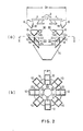
- Figures 3(a) and (b) show a second embodiment of this invention.
- the structure of the first embodiment is expanded horizontally as maintaining the outer diameter D1 of the prior art device. With this expansion, it becomes possible to increase the gate width from b1 to b2 thereby increasing the flow rate to improve the machine efficiency.
- This embodiment will not be described further since it is similar in both structure and operation to the above-described first embodiment.
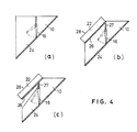
- Figure 4(a) shows a variation of the auxiliary hopper structure 20, in which the upper chute 22 of Figures 2 and 3 is removed and the lower chute 24 is used in common for the product discharged from weigh and auxiliary hopper 8 and 10.
- Figure 4(b) shows another variation of the auxiliary hopper structure 20 in which the slide plate 26 of the upper chute 22 is formed integral with the partition plate 27 of the auxiliary hopper 10 and a pair of guide walls 28 are attached thereto to form the upper chute 22.
- Figure 4(c) shows a further variation in which the slide plate 26 of the upper chute 22 covers a part of the auxiliary hopper 10 and also has a pair of guide walls 28.
- the inner and outer gates may be attached to a single bottom outlet of each weigh hopper, instead of two separate outlets.
- the improved auxiliary hopper structure contributes to substantial reduction in size of the collection chute and this reduced size of collection chute and the compact structure of the auxiliary hopper structure contribute also to easy detachment and handling thereof by a sole operator, thereby facilitating his cleaning operation and like operations for maintenance service.
Landscapes
- Physics & Mathematics (AREA)
- General Physics & Mathematics (AREA)
- Filling Or Emptying Of Bunkers, Hoppers, And Tanks (AREA)
Abstract
Description
- This invention relates to a combination weigher and, especially, to a combination weigher having auxiliary hoppers.
- Figures 1(a) and 1(b) show a specific arrangement of mechanical components of a prior art combination weigher, which is suggested, for example, in the Japanese patent opening gazette No. 58-41326. In the drawings, a plurality of electromagnetic feeders 4 are radially arranged around a dispersion feeder 2 and a
feed hopper 6 is disposed under the distal end of each electromagnetic feeder 4. Aweigh hopper 8 is disposed under eachfeed hopper 6 and anauxiliary hopper 10 is disposed under eachweight hopper 8. The feed, weight andauxiliary hoppers weigh hopper 8 has anouter gate 12a for discharging product directly downward and aninner gate 12b for feeding product into the underlyingauxiliary hopper 10. Accordingly, theauxiliary hoppers 10 are arranged annularly under theinner gates 12b. Acollection chute 14 is disposed under theauxiliary hoppers 10 for collecting product discharged fromweigh hoppers 8 and/orauxiliary hoppers 10. Eachauxiliary hopper 10 has adischarge gate 16 adapted to open inwardly as shown in phantom 16ʹ and eachfeed hopper 6 also has asimilar discharge gate 18. - However, the above-mentioned combination weigher having
auxiliary hoppers 10 arranged annularly under theinner gates 12b ofweigh hoppers 8 and each having thegate 16 opening inwardly has such a problem as follows. - When the
auxiliary hoppers 10 are arranged annularly and theirgates 16 having the same width b1 as each hopper are opened inwardly as shown by 16ʹ, they must be positioned so that the lower edges of the opened gates 16ʹ never enter a corresponding regular polygon having a side length b1, in order to ensure anyhopper 10 to open itsgate 16 without any interference of the other gates. On the other hand, eachauxiliary hopper 10 is disposed directly under the inner gate 10b of thecorresponding weigh hopper 8 and, therefore, a funnel-like collection chute 14 must have a significantly large diameter sufficient for completely collecting the product discharged from theouter gates 12a ofweigh hoppers 8. In the prior art combination weigher, such a bulky collection chute has resulted not only in an increased overall machine size and corresponding increase in the machine occupation area, but also in substantial difficulty in the maintenence service. While the gate width b1 may be reduced to remove the above-mentioned problem, this will result in reduction in the flow rate of product which causes undesirable reduction in the machine efficiency. Although the flow rate can be maintained by increasing the height of gate, this will result in undesirable increase in the machine height. - Accordingly, an object of this invention is to provide an improved structure of combination weigher which enables to reduce the collection chute diameter to obtain reduction of the machine occupation area and increase in the facility of maintenance service, without increase in the machine height and reduction in the machine efficiency.
- This object can be attained in accordance with this invention which provides a combination weigher having a plurality of weigh hoppers arranged on a circle and a plurality of auxiliary hoppers respectively disposed under the weigh hoppers. Each weigh hopper has an inner gate adapted to discharge its content inside of said circle and an outer gate adapted to discharge its content outside of said circle. A funnel-like common collection chute is disposed under the auxiliary hoppers for collecting product discharged from the weigh and/or auxiliary hoppers.
- As a feature of this invention, each auxiliary hopper is located directly under the outer gate of the corresponding weigh hopper and, as another feature of this invention, each auxiliary hopper is provided with chute means for directing the discharged product to the center of the collection chute.
- These and other objects and features of this invention will be best understood from the following description with reference to the accompanying drawings.
- In the drawings:
- Figure 1(a) is a schematic side view representing a mechanical configuration of a prior art combination weigher pertinent to this invention;
- Figure 1(b) is a sectional plan view along a line I-I of Figure 1(a);
- Figure 2(a) is a schematic side view representing, partly in section, a mechanical configuration of an embodiment of combination weigher according to this invention;
- Figure 2(b) is a sectional plan view along a line II-II of Figure 2(a);
- Figure 3(a) is a schematic side view representing, partly in section, a mechanical configuration of another embodiment of combination weigher according to this invention;
- Figure 3(b) is a sectional plan view along a line III-III of Figure 3(a); and
- Figure 4(a), (b) and (c) are sectional side views representing three variations of the auxiliary hopper structure according to this invention.
- Throughout the drawings, the same reference numerals are given to corresponding components.
- Referring to Figures 2(a) and (b) showing a first embodiment, a plurality of electromagnetic feeders 4 are ar ranged radially around a dispersion feeder 2 and a
feed hopper 6 is disposed under the distal end of each electromagnetic feeder 4. Thus, thefeed hoppers 6 are arranged annularly. Eachfeed hopper 6 has adischarge gate 18 for closing its bottom outlet. Aweigh hopper 8 is disposed under eachfeed hopper 6 for receiving product therefrom when thegate 18 is opened. Thus, theweigh hoppers 8 are also arranged annularly. Eachweigh hopper 8 is coupled to aload cell 30 for sensing the weight of product fed in thehopper 8. As in the aforementioned prior art device, eachweight hopper 8 has two bottom outlets respectively directed to the outside and inside of the circle formed by theweigh hoppers 8 and these outlets are respectively closed by outer andinner discharge gates weigh hopper 8, disposed is anauxiliary hopper structure 20 according to this invention. - Each
auxiliary hopper structure 20 is formed as a discrete compact unit comprising a pair of triangular side plates and two slanting slide plates which form upper andlower chutes lower chute 24 is partitioned by avertical gate door 16 to form anauxiliary hopper 10. A funnel-like collection chute 14 which may be much smaller than that of the prior art is disposed under theauxiliary hopper structures 20. Each auxiliary hopper structure is designed and positioned so that the content of theoverhead weigh hopper 8 is fed to theauxiliary hopper 10 when theouter gate 12a opens, while it is discharged through theupper chute 22 into thecollection chute 14 when theinner gate 12b opens. The content of theauxiliary hopper 10 is discharged through thelower chute 24 into thecollection chute 14 when thegate 16 opens. - In operation, product to be weighed is fed through the
feed hoppers 6 fo theunderlying weigh hoppers 8 and weighed by the associatedload cells 30. The emptiedfeed hoppers 6 are reloaded by the electromagnetic feeders 4. The re sultant weight indicative signals from theload cells 30 are digitized by A/D convertors (not shown) and supplied to a control unit (not shown) composed of a microcomputer or the like. Then, the control unit acts to open theouter gates 12a of thecorresponding weigh hoppers 8 to transfer the contents thereof to the correspondingauxiliary hoppers 10. Upon completion of this transference, the control unit acts to open thedischarge gates 18 of thecorresponding feed hoppers 6 to reload the emptiedweigh hoppers 8 and thesensors 30 provide the weight informations of the new product to the control unit. Thus, the control unit is now keeping the weights of product contained in all weigh andauxiliary hoppers feed hoppers 6 and then drives the dispersion feeder 2 to feed new product to the electromagnetic feeders 4. Upon completion of the combination selecting operation, the control unit acts to open thegates 12b and/or 16 of those weigh and/orauxiliary hoppers 8 and/or 10 which contain product batches whose weights form the selected combination. The contents of these hoppers are discharged through both upper andlower chutes collection chute 14 for delivery. Upon completion of this discharge, the control unit acts to open theouter gate 12a ofweigh hopper 8 corresponding to each emptiedauxiliary hopper 10 and, also, thedischarge gate 18 offeed hopper 6 corresponding to each emptiedweigh hopper 8, to reload these emptied hoppers. If the corresponding weigh andauxiliary hoppers - It can be understood from comparison of Figures 1 and 2 that the outer diameter D2 of this embodiment is less than that of the prior art device D1 though the auxiliary hopper gates of the both have the same width b1. This is because the
weigh hoppers 8 have been moved inward with respect to the original position of theauxiliary hoppers 10 though the size of polygon formed by the inner edges of thechute 24 is unchanged. Moreover, thecollection chute 14 in this embodiment has been substantially reduced in size. - Figures 3(a) and (b) show a second embodiment of this invention. In this embodiment, the structure of the first embodiment is expanded horizontally as maintaining the outer diameter D1 of the prior art device. With this expansion, it becomes possible to increase the gate width from b1 to b2 thereby increasing the flow rate to improve the machine efficiency. This embodiment will not be described further since it is similar in both structure and operation to the above-described first embodiment.
- Figure 4(a) shows a variation of the
auxiliary hopper structure 20, in which theupper chute 22 of Figures 2 and 3 is removed and thelower chute 24 is used in common for the product discharged from weigh andauxiliary hopper auxiliary hopper structure 20 in which theslide plate 26 of theupper chute 22 is formed integral with thepartition plate 27 of theauxiliary hopper 10 and a pair ofguide walls 28 are attached thereto to form theupper chute 22. Figure 4(c) shows a further variation in which theslide plate 26 of theupper chute 22 covers a part of theauxiliary hopper 10 and also has a pair ofguide walls 28. - The above description has been made only for the purpose of illustration but not for limitation. Various modifications and variations can be made within the scope of this invention. For example, the inner and outer gates may be attached to a single bottom outlet of each weigh hopper, instead of two separate outlets.
- As described above, with the structure according to this invention, it becomes possible to reduce the overall diameter of the machine, thereby reducing its occupation area. Moreover, the improved auxiliary hopper structure contributes to substantial reduction in size of the collection chute and this reduced size of collection chute and the compact structure of the auxiliary hopper structure contribute also to easy detachment and handling thereof by a sole operator, thereby facilitating his cleaning operation and like operations for maintenance service.
Claims (5)
Applications Claiming Priority (2)
| Application Number | Priority Date | Filing Date | Title |
|---|---|---|---|
| JP1986203066U JPH0452657Y2 (en) | 1986-12-26 | 1986-12-26 | |
| JP203066/86 | 1986-12-26 |
Publications (3)
| Publication Number | Publication Date |
|---|---|
| EP0273644A2 true EP0273644A2 (en) | 1988-07-06 |
| EP0273644A3 EP0273644A3 (en) | 1989-02-22 |
| EP0273644B1 EP0273644B1 (en) | 1991-04-10 |
Family
ID=16467775
Family Applications (1)
| Application Number | Title | Priority Date | Filing Date |
|---|---|---|---|
| EP87311098A Expired - Lifetime EP0273644B1 (en) | 1986-12-26 | 1987-12-16 | Combination weigher |
Country Status (5)
| Country | Link |
|---|---|
| US (1) | US4825896A (en) |
| EP (1) | EP0273644B1 (en) |
| JP (1) | JPH0452657Y2 (en) |
| KR (1) | KR910005754Y1 (en) |
| DE (1) | DE3769302D1 (en) |
Cited By (1)
| Publication number | Priority date | Publication date | Assignee | Title |
|---|---|---|---|---|
| EP1845348A1 (en) * | 2005-01-06 | 2007-10-17 | Yamato Scale Co., Ltd. | Combination balance |
Families Citing this family (7)
| Publication number | Priority date | Publication date | Assignee | Title |
|---|---|---|---|---|
| US5545856A (en) * | 1994-01-07 | 1996-08-13 | The Paxall Group, Inc. | Distribution system for a combination weigher or the like |
| IT1314842B1 (en) * | 2000-06-07 | 2003-01-16 | Sasib Packaging Italia Srl | COMBINATION SCALE FOR BULK PRODUCTS OF ELONGATED FORM AS FOOD PASTA, OR OTHER |
| JP3706331B2 (en) * | 2001-11-06 | 2005-10-12 | 大和製衡株式会社 | Positive displacement feeder for powder and granule combination balance |
| CN101061378B (en) * | 2004-11-25 | 2010-09-29 | 川西胜三 | Combination balance |
| DE102007019246A1 (en) * | 2007-04-24 | 2008-10-30 | Hastamat Verpackungstechnik Gmbh | Apparatus and method for combining a number of portions of a bar-shaped, lumpy or pourable product and for the synchronized transfer of the portions for connection to a partial combination weigher |
| US20090101478A1 (en) * | 2007-10-23 | 2009-04-23 | Christopher Dale | Inline conveyor scale |
| GB201407651D0 (en) * | 2014-05-01 | 2014-06-18 | Ishida Europ Ltd | Method and apparatus for grading food pieces |
Citations (3)
| Publication number | Priority date | Publication date | Assignee | Title |
|---|---|---|---|---|
| EP0074260A2 (en) * | 1981-09-04 | 1983-03-16 | Kabushiki Kaisha Ishida Koki Seisakusho | Combinatorial weighing apparatus |
| GB2121626A (en) * | 1982-06-01 | 1983-12-21 | Yamato Scale Co Ltd | Combination weighing machine |
| EP0140624A2 (en) * | 1983-10-15 | 1985-05-08 | Kabushiki Kaisha Ishida Koki Seisakusho | Combinatorial weighing |
Family Cites Families (1)
| Publication number | Priority date | Publication date | Assignee | Title |
|---|---|---|---|---|
| US4618012A (en) * | 1985-01-14 | 1986-10-21 | Yamato Scale Company, Limited | Combination weighing machine |
-
1986
- 1986-12-26 JP JP1986203066U patent/JPH0452657Y2/ja not_active Expired
-
1987
- 1987-12-16 DE DE8787311098T patent/DE3769302D1/en not_active Expired - Lifetime
- 1987-12-16 EP EP87311098A patent/EP0273644B1/en not_active Expired - Lifetime
- 1987-12-23 US US07/137,256 patent/US4825896A/en not_active Expired - Lifetime
- 1987-12-23 KR KR2019870022872U patent/KR910005754Y1/en not_active IP Right Cessation
Patent Citations (3)
| Publication number | Priority date | Publication date | Assignee | Title |
|---|---|---|---|---|
| EP0074260A2 (en) * | 1981-09-04 | 1983-03-16 | Kabushiki Kaisha Ishida Koki Seisakusho | Combinatorial weighing apparatus |
| GB2121626A (en) * | 1982-06-01 | 1983-12-21 | Yamato Scale Co Ltd | Combination weighing machine |
| EP0140624A2 (en) * | 1983-10-15 | 1985-05-08 | Kabushiki Kaisha Ishida Koki Seisakusho | Combinatorial weighing |
Cited By (2)
| Publication number | Priority date | Publication date | Assignee | Title |
|---|---|---|---|---|
| EP1845348A1 (en) * | 2005-01-06 | 2007-10-17 | Yamato Scale Co., Ltd. | Combination balance |
| EP1845348A4 (en) * | 2005-01-06 | 2011-02-09 | Yamato Scale Co Ltd | Combination balance |
Also Published As
| Publication number | Publication date |
|---|---|
| DE3769302D1 (en) | 1991-05-16 |
| US4825896A (en) | 1989-05-02 |
| EP0273644A3 (en) | 1989-02-22 |
| KR910005754Y1 (en) | 1991-08-02 |
| JPH0452657Y2 (en) | 1992-12-10 |
| EP0273644B1 (en) | 1991-04-10 |
| KR880012871U (en) | 1988-08-29 |
| JPS63105828U (en) | 1988-07-08 |
Similar Documents
| Publication | Publication Date | Title |
|---|---|---|
| US4538693A (en) | Weighing machine | |
| US4967856A (en) | Combination weighing machine | |
| EP0273644A2 (en) | Combination weigher | |
| EP1873502B1 (en) | Combination balance for weighing a mixture of products | |
| US4569446A (en) | Method and apparatus for feeding a product including fines | |
| EP1164365B1 (en) | Combination weighing and counting device | |
| WO1988003262A1 (en) | Combination weigher with multiple compartment weighing receptacles | |
| US4966273A (en) | Distributive supply device for combinatorial weighing apparatus | |
| JPH0217301Y2 (en) | ||
| US4537229A (en) | Automatic weighing apparatus and method | |
| US6271485B1 (en) | Article alignment device | |
| US6447235B1 (en) | Waste collection device | |
| JPH02159310A (en) | Charging device for blast furnace | |
| EP1393024B1 (en) | In-feed weighing method and apparatus | |
| EP0181738B1 (en) | Flow control apparatus | |
| JPS62175625A (en) | Goods feeder | |
| EP1363111A1 (en) | Combined weighing equipment | |
| CA2287955C (en) | Product-discharging device for a product supply system | |
| US7667147B2 (en) | Controller for a combination weigher | |
| US4766964A (en) | Apparent density measuring device | |
| RU95113963A (en) | MICRODOSING DEVICE | |
| EP3792605B1 (en) | Timing hopper and combination weighing device | |
| WO2004042335A1 (en) | Automatic combination weighing apparatus | |
| CA2212855A1 (en) | Method to maximally utilize the loading capacity of an individual wagon and the train when loading with bulk material | |
| JPS60161530A (en) | Combination balance |
Legal Events
| Date | Code | Title | Description |
|---|---|---|---|
| PUAI | Public reference made under article 153(3) epc to a published international application that has entered the european phase |
Free format text: ORIGINAL CODE: 0009012 |
|
| AK | Designated contracting states |
Kind code of ref document: A2 Designated state(s): DE FR GB |
|
| PUAL | Search report despatched |
Free format text: ORIGINAL CODE: 0009013 |
|
| AK | Designated contracting states |
Kind code of ref document: A3 Designated state(s): DE FR GB |
|
| 17P | Request for examination filed |
Effective date: 19890314 |
|
| 17Q | First examination report despatched |
Effective date: 19890727 |
|
| GRAA | (expected) grant |
Free format text: ORIGINAL CODE: 0009210 |
|
| AK | Designated contracting states |
Kind code of ref document: B1 Designated state(s): DE FR GB |
|
| REF | Corresponds to: |
Ref document number: 3769302 Country of ref document: DE Date of ref document: 19910516 |
|
| ET | Fr: translation filed | ||
| PGFP | Annual fee paid to national office [announced via postgrant information from national office to epo] |
Ref country code: FR Payment date: 19911209 Year of fee payment: 5 |
|
| PLBE | No opposition filed within time limit |
Free format text: ORIGINAL CODE: 0009261 |
|
| STAA | Information on the status of an ep patent application or granted ep patent |
Free format text: STATUS: NO OPPOSITION FILED WITHIN TIME LIMIT |
|
| 26N | No opposition filed | ||
| PG25 | Lapsed in a contracting state [announced via postgrant information from national office to epo] |
Ref country code: FR Effective date: 19930831 |
|
| REG | Reference to a national code |
Ref country code: FR Ref legal event code: ST |
|
| REG | Reference to a national code |
Ref country code: GB Ref legal event code: IF02 |
|
| PGFP | Annual fee paid to national office [announced via postgrant information from national office to epo] |
Ref country code: GB Payment date: 20061213 Year of fee payment: 20 |
|
| PGFP | Annual fee paid to national office [announced via postgrant information from national office to epo] |
Ref country code: DE Payment date: 20061214 Year of fee payment: 20 |
|
| REG | Reference to a national code |
Ref country code: GB Ref legal event code: PE20 |
|
| PG25 | Lapsed in a contracting state [announced via postgrant information from national office to epo] |
Ref country code: GB Free format text: LAPSE BECAUSE OF EXPIRATION OF PROTECTION Effective date: 20071215 |