EP0272043A2 - Diagnostic device - Google Patents
Diagnostic device Download PDFInfo
- Publication number
- EP0272043A2 EP0272043A2 EP87310827A EP87310827A EP0272043A2 EP 0272043 A2 EP0272043 A2 EP 0272043A2 EP 87310827 A EP87310827 A EP 87310827A EP 87310827 A EP87310827 A EP 87310827A EP 0272043 A2 EP0272043 A2 EP 0272043A2
- Authority
- EP
- European Patent Office
- Prior art keywords
- well
- test device
- diagnostic test
- layer
- plate
- Prior art date
- Legal status (The legal status is an assumption and is not a legal conclusion. Google has not performed a legal analysis and makes no representation as to the accuracy of the status listed.)
- Granted
Links
Images

Classifications
-
- B—PERFORMING OPERATIONS; TRANSPORTING
- B01—PHYSICAL OR CHEMICAL PROCESSES OR APPARATUS IN GENERAL
- B01L—CHEMICAL OR PHYSICAL LABORATORY APPARATUS FOR GENERAL USE
- B01L3/00—Containers or dishes for laboratory use, e.g. laboratory glassware; Droppers
- B01L3/50—Containers for the purpose of retaining a material to be analysed, e.g. test tubes
- B01L3/502—Containers for the purpose of retaining a material to be analysed, e.g. test tubes with fluid transport, e.g. in multi-compartment structures
- B01L3/5025—Containers for the purpose of retaining a material to be analysed, e.g. test tubes with fluid transport, e.g. in multi-compartment structures for parallel transport of multiple samples
- B01L3/50255—Multi-well filtration
-
- B—PERFORMING OPERATIONS; TRANSPORTING
- B01—PHYSICAL OR CHEMICAL PROCESSES OR APPARATUS IN GENERAL
- B01D—SEPARATION
- B01D61/00—Processes of separation using semi-permeable membranes, e.g. dialysis, osmosis or ultrafiltration; Apparatus, accessories or auxiliary operations specially adapted therefor
- B01D61/14—Ultrafiltration; Microfiltration
- B01D61/18—Apparatus therefor
-
- G—PHYSICS
- G01—MEASURING; TESTING
- G01N—INVESTIGATING OR ANALYSING MATERIALS BY DETERMINING THEIR CHEMICAL OR PHYSICAL PROPERTIES
- G01N33/00—Investigating or analysing materials by specific methods not covered by groups G01N1/00 - G01N31/00
- G01N33/48—Biological material, e.g. blood, urine; Haemocytometers
- G01N33/50—Chemical analysis of biological material, e.g. blood, urine; Testing involving biospecific ligand binding methods; Immunological testing
- G01N33/53—Immunoassay; Biospecific binding assay; Materials therefor
- G01N33/543—Immunoassay; Biospecific binding assay; Materials therefor with an insoluble carrier for immobilising immunochemicals
- G01N33/54366—Apparatus specially adapted for solid-phase testing
Definitions
- the present invention relates to a diagnostic device useful in chemical and particularly biological and biochemical assays.
- the invention is particularly directed to multiple well filtration devices, such as microtitration plates, able to retain fluids for extended periods of time and, under specified conditions, to remove liquid quickly and completely.
- Diagnostic devices including test plates, and, in particular, multiple well or microtitration plates, have been used for both quantitative and, especially, qualitative chemical and biological tests for decades.
- Various designs and configurations have proliferated as the area of enzyme immunoassays has expanded.
- Test devices and, particularly, plates having a plurality of wells which include microporous membrane filters have also become routinely used in clinical laboratories in recent times. This has resulted, at least in part, from development of cell and tissue culture techniques and assays in fields such as virology and immunology.
- test devices have advantages in that they provide a single test apparatus rather than multiple test apparatus and also provide side-by-side comparison of test results within a single device.
- Such plates have several significant shortcomings. Many of the materials used to form at least the bottom portion of such test devices are porous in nature and permit liquid in the wells to pass through the bottom either by gravity flow or capillary action.
- cross-talk A second common problem encountered with the use of such multiple well test plates involves a phenomenon known by some as "cross-talk". Such occurrence involves the migration of liquid, sometimes in the form of a pendant drop suspended from the bottom of one well, to an adjacent well.
- Two causes of the type of migration known as cross-talk are (1) wicking of fluid or diffusion of solutes laterally through the membrane between adjacent wells, and (2) coalescing of pendant drops suspended below the wells.
- Such migration may lead to spurious results, both when the liquid removed from the wells is to be analyzed or, possibly, when liquid flows back into an adjacent well.
- the present invention is directed to a diagnostic test device which includes a plate having at least one well, and preferably a plurality of wells, each well having an open bottom. At the bottom of the well and forming a hydrophobic, liquid-tight seal at the periphery thereof is placed a composite membrane comprising three layers which are, preferably, in intimate contact with one another. Proceeding from the top or upstream side to the bottom or downstream side of the composite membrane, in sequence, the first layer is a reaction or filtration layer formed from a thin, liquophilic microporous membrane, such as a membrane of filtration material.
- reaction layer After transfer of a test sample to a well and removal of liquid, in those situations when subsequent reactions are performed on substances retained by the composite membrane, it is the reaction layer which generally forms the site at which reaction occurs.
- a second or sealing layer Placed be onlylow the reaction layer is a second or sealing layer.
- This second, preferably porous layer functions as both a means of securing or adhering the reaction layer to a liquophobic barrier layer as well as forming a liquophobic seal at the periphery of the well where the side walls of the well contact the composite membrane. Because of the liquophobic seal, cross-talk by lateral diffusion or wicking is eliminated. Preferred is a hydrophobic material for the second layer.
- the third or downstream layer is a liquophobic barrier layer.
- This layer includes a small aperture located substantially at the center of the well.
- This barrier layer substantially eliminates dripping, enhances isolation of each well in multiple well devices, and inhibits lateral migration of a pendant liquid drop from one well to another well.
- the multiple well diagnostic plate device in accordance with the present invention permits greater or enhanced sensitivity in tests performed with the device as a result of the increased surface area afforded by the porous nature of the reaction layer.
- the substantially increased sensitivity resulting from the substantially higher surface area of the microporous membrane provides results making the difference between operability and inoperability of the particular protocol.
- the rapid and efficient removal of sample and reagent solutions only after application of a pressure differential permits the solutions to be removed rapidly and completely without the use of a pipette.
- the diagnostic plate employed in accordance with the present invention may have a variety of forms and be made from any suitable material.
- Preferred materials are thermoplastic resins including polyolefins, such as polypropylene, and polystyrene.
- the plate may contain as few as one well or as many wells as can be arranged within the plate and effectively serviced by the source of differential pressure, i.e., reduced or positive pressure, employed.
- Filtration plates currently being used typically have ninety-six wells and this number of wells is not incompatible with the present invention.
- the wells in such devices are closely spaced for efficiency and economics. As a result, the potential for cross-talk in such devices is enhanced.
- the wells themselves may be formed in the shape of cylinders projecting upwardly from a base of the plate or, as preferred, may be formed as cylinders projecting downwardly from an upper surface or plane of the plate.
- Each of the wells may have vertical or downwardly tapered side walls, the latter forming conical or tapered wells.
- each well may be varied depending upon the application of the device.
- the well will typically have a cylindrical configuration, but other configurations, such as a square or rectangle, may also be used.
- the diameter of the well may vary considerably depending upon such factors as the size of the sample to be used in each well and whether the device is to be used for diagnostic purposes, its most widespread anticipated application, or for separation and isolation of substances.
- the size of the liquid sample used and, therefore, the dimensions of the well may also depend on the sensitivity of the reaction performed in the well when the device is used for diagnostic purposes.
- the diameter of a well will be from 1 mm to 100 mm.
- the diameter of a well will be 2 mm to 25 mm.
- the height of a well is 1 mm to 75 mm, preferably 5 mm to 10 mm.
- each well has an opening formed therein.
- the well may have the configuration of an open cylinder or of a hollow truncated or frustoconical cone.
- the periphery or brim of the opening to which the composite membrane is adhered generally forms a horizontal surface.
- the composite membrane comprises at least three layers.
- the first or uppermost layer constitutes a "reaction layer" which, when the device in accordance with the present invention is used for diagnostic purposes, is the layer in or upon which reagents are added and tests are performed.
- This layer may also be used as a filtration medium to separate liquid and solid components when the material retained by the composite membrane is not intended for further characterization.
- the material from which this layer is formed like the other layers, must not react adversely with substances found in either the samples, reagents or solvents employed in the analyses.
- the reaction layer must be formed from a liquophilic, microporous membrane, typically having an absolute pore rating of 0.001 to 20 microns, preferably 0.02 to 8 microns, and most preferably 0.2 to 3 microns.
- the reaction layer preferably is also skinless. Materials which are suitable for use as the reaction layer also have voids volumes in the range of 60 to 90 percent, preferably in the range of 75 to 90 percent. Preferred materials are hydrophilic in nature and are, therefore, easily water-wettable and tend to freely pass aqueous solutions. Examples of liquophilic materials which may be used in accordance with the present invention include, but are not limited to, polyamides, such as nylon 66, polyvinylidene difluoride, cellulose esters, and nitrocellulose.
- Liquophilicity refers to the wettability of the membrane by the liquid(s) with which it is contacted.
- the wettability or liquophilicity of a solid structure is a function of that structure's critical surface energy and the surface tension of the applied liquid. If the critical surface energy is at least as high as the surface tension of the liquid, the liquid will spontaneously wet the solid structure.
- a microporous membrane having a critical surface energy of 72 dynes/cm or higher will be wetted by water which has a surface tension of 72 dynes/cm, i.e., it is hydrophilic.
- porous structure membrane
- the capability of a porous structure (membrane) to be wetted by a liquid can be determined by placing a drop of liquid on the porous structure.
- the angle of contact provides a quantitative measure of wetting. A very high angle of contact indicates poor wetting, while a zero angle of contact defines complete or perfect wetting.
- Materials used in accordance with the subject invention as the wettable or liquophilic porous layer are characterized by being readily or spontaneously wetted by the applied liquid and have a low angle of contact with the applied liquid.
- Suitable materials should also be capable of being treated with and retaining or immobilizing a substance being analyzed and/or a reactant which may be used to perform a specified test or reaction with the substance being analyzed for in a sample.
- the reactant which may be of ionic, molecular, or macromolecular nature may be immobilized on the reaction layer by strong physical forces or by being bonded in some manner, such as covalent chemical coupling, to the surface of the microporous, liquophilic reaction membrane layer.
- the term “surface” or “surface area” refers not only to the gross surface(s) of the structure but also, in those cases where a microporous structure such as a membrane is under consideration, to the surfaces of the micropores, i.e., the interior surfaces of the structure which are contacted by fluid during use.
- the exposed planar or gross area of the material is herein referred to as the "reaction layer area”, “microporous reaction layer area”, “reaction layer membrane area”, or the like.
- Wettability or liquophilicity is a requisite of the materials used for the microporous reaction layer in accordance with the present invention. It is particularly preferred that such materials be capable of being spontaneously wetted. Some of the materials which are suitable or preferred for use as the reaction layer in accordance with the present invention are intrinsically hydrophilic or water-wettable. Others may be modified to render them hydrophilic. BIODYNE® is an N66 polyamide, microporous membrane commercially available from Pall Corporation which is inherently water-wettable by virtue of its method of manufacture (see U.S. Patent 4,340,479).
- Polyvinylidene fluoride membranes are not inherently water-wettable but can be rendered such by an appropriate surface treatment.
- Microporous, polyvinylidene fluoride membranes which have been treated to render them hydrophilic are commercially available.
- wettability or liquophilicity is a function of the critical surface energy of the solid structure and the surface tension of the liquid. Wettability may also be expressed in terms of intrusion pressure which may be defined as the applied pressure required for liquid to penetrate into the pores of the membrane.
- Materials which are preferred for the reaction layer also have large surface areas. This feature permits a greater amount or higher concentration of reactant to be immobilized in the reaction layer. Accordingly, higher sensitivities may be achieved using the test plate of the present invention.
- Polyamides preferred for use in accordance with the present invention include nylons of the type described in U.S. Patent 4,340,479.
- the hydrophilic, microporous, polyamide filter membranes disclosed in U.S. Patent 4,340,479 are membranes prepared from alcohol-insoluble polyamide resins having a methylene to amide ratio in the range of 5:1 to 7:1.
- Membranes of this group include copolymers of hexamethylene diamine and adipic acid (nylon 66), copolymers of hexamethylene diamine and sebacic acid (nylon 610), homopolymers of poly- -caprolactam (nylon 6), and copolymers of hexamethylene diamine and azelaic acid (nylon 69).
- a membrane material of this description which is particularly useful for the present invention is a microporous, hydrophilic nylon membrane commerically available from Pall Corporation under the trademark BIODYNE®.
- IMMUNODYNETM is a modified CARBOXYDYNE® membrane, also available from Pall Corporation.
- CARBOXYDYNE® is a hydrophilic, microporous, skinless nylon 66 membrane with controlled surface properties formed by the cocasting process described in U.S. Patent 4,707,266, as discussed below, specifically by cocasting nylon 66 and a polymer containing an abundance of carboxyl groups to form a membrane having controlled surface properties characterized by carboxyl functional groups at its surfaces.
- IMMUNODYNETM membranes may be prepared from CARBOXYDYNE® membranes by treating them with trichloro-s-triazine in the manner described in U.S. Patent 4,693,985, discussed below.
- hydrophilic, microporous, skinless polyamide membranes with controlled surface properties of the type described in (1) U.S. Patent 4,707,266 and in (2) U.S. Patent 4,702,840.
- the hydrophilic, microporous, substantially alcohol-insoluble polyamide membranes with controlled surface properties of these patents are formed by cocasting an alcohol-insoluble polyamide resin with a water-soluble, membrane-surface-modifying polymer having functional polar groups.
- the polyamide membranes in accordance with the present invention having controlled surface properties are also skinless; that is, they are characterized by through pores extending from surface-tosurface which are of substantially uniform size and shape. If desired, however, materials having tapered through pores, i.e., pores which are larger at one surface of the sheet, narrowing as they approach the opposite surface of the sheet, may be used.
- the surface-modifying polymers used to prepare the polyamide membranes with controlled surface properties, useful in accordance with the present invention comprise polymers which contain substantial proportions of chemically functional groups, such as hydroxyl, carboxyl, amine, and imine groups.
- the membranes include, at their surfaces, high concentrations of functional groups such as hydroxyl, carboxyl, imine, or a combination of any of the above groups which do not react with one another.
- polyamide membranes having controlled surface properties have higher concentrations of carboxyl or imine groups at their surfaces than the preferred microporous, hydrophilic, skinless polyamide membranes described above which do not have controlled surface properties, i.e., those which are formed from the preferred polyamide resin but are not cocast with surface-modifying polymer.
- the reaction layer may be treated by any method known to one of skill in the art to deposit and/or bind reagents thereto.
- the reagent may be of an ionic, molecular, or macromolecular nature.
- the reagent When used as a diagnostic tool to provide a visible change, the reagent may be one or a combination of substances which is initially colorless and which, upon reaction with a suitable material, provides an optically measurable response.
- suitable labels such as the formation between the deposited reagent and the material for which testing is being conducted of a complex or compound which is appropriately labeled by any known technique, such as enzymatic/substrate labels or the like.
- the present invention is expected to have greatest application to, and a preferred embodiment includes, a composite membrane in which the reaction layer has been pretreated with at least one test reagent.
- pretreatment is conducted after the composite membrane has been sealed to the wells but before the device is shipped to a user. If the reagent(s) is not heat sensitive, the membrane may be treated before assembling the composite membrane.
- This patent describes a method for immobilizing a wide range of biologically active substances as acceptor molecules on active membranes.
- the acceptor-bound membranes described in the patent are capable of immobilizing and binding a wide variety of biologically-active compounds, specifically ligands, to the acceptor molecules.
- reaction layers or membranes permits the testing of bodily fluids, such as blood, serum, plasma, urine, saliva, and the like, and testing for particular substances by chemical assays or immunoassays, such as those where a specific label is employed, such as one indicating enzyme activity or an electromagnetic energy absorbing and/or emitting label, such as a fluoroescent label.
- the macromolecules used as reagents and bound to the reaction layer or which are assayed for using the device in accordance with the present invention generally include materials of a biological nature and are frequently proteinaceous in nature.
- the reagent or acceptor molecule bound directly to the reaction layer or the ligand being tested for include such substances as immunoglobulins or antibodies, either polyclonal or monoclonal, antigenic substances, apoproteins, receptors, glycoproteins, lectins, carbohydrates, hormones, enzymes, carrier proteins, heparin, coagulation factors, enzyme substrates, inhibitors, cofactors, nucleic acids, etc.
- a porous sealing layer Placed below, preferably in intimate contact with or, most preferably, adhered, bonded, or otherwise secured to the reaction layer, particularly at the periphery of each well, is a porous sealing layer which serves several purposes. Strongly preferred for use as a sealing layer is a very porous liquophobic structure.
- the term "liquophobic" as used herein is effectively the obverse of the term “liquophilic", that is, a liquophobic material has a critical surface energy lower than the surface tension of the applied liquid and is not readily or spontaneously wetted by the applied liquid(s). Liquophobic materials are characterized, then, by a high contact angle between a drop of liquid placed on the surface and the surface.
- the porous sealing layer assists in bonding the reaction layer to the barrier layer. It also makes it possible to form a liquophobic seal at the periphery of the well, thereby eliminating cross-talk by diffusion or wicking.
- the use of such material in the sealing layer also provides the composite membrane with the ability to withstand or maintain a pressure differential. For example, it prevents, without the application of vacuum or high pressures, penetration of liquid through the composite membrane and the concomitant loss of liquid from the well by dripping.
- a pressure differential For example, it prevents, without the application of vacuum or high pressures, penetration of liquid through the composite membrane and the concomitant loss of liquid from the well by dripping.
- Materials suitable for use as the sealing layer in addition to being liquophobic, preferably are hydrophobic and are also significantly more porous than the reaction layer. Such material may be present in sheet or fiber form, either woven or unwoven.
- Suitable materials include polyamides, linear polyesters, such as esters of ethylene glycol and terephthalic acid, polyolefins, such as polypropylene, polyethylene, polymethylpentene, and polyisobutylene, as well as copolymers formed by copolymerizing the monomers used to form the aforementioned homopolymers, such as ethylene-propylene copolymers. Mixtures or blends of such polymers can also be used.
- the polyolefins are preferred and polypropylene is particularly preferred.
- the third or downstream layer constitutes a barrier layer which, preferably, is in intimate contact with or, most preferably, is adhered, bonded, or otherwise secured to the sealing layer, particularly at the periphery of each well. It is this layer, provided with at least one, and preferably only one, aperture located substantially at the center of the well, which permits a drop of liquid to pass from the well, under application of positive or negative gauge pressure, i.e., super atmospheric pressure applied upstream of the composite membrane or reduced pressure applied downstream of the membrane, and to drop from the plate without radial migration to another well.
- the apertures can also serve as restriction means, controlling the flow rate of liquid through the composite membrane.
- the barrier layer because of the nature of the material used therein, i.e., a highly liquophobic, preferably hydrophobic, material, enhances isolation between wells and forces the liquid passing through the composite membrane to form small drops at the hole in the barrier layer.
- These drops rather than spreading radially when passing through a porous or microporous liquophilic material (such as the material of the reaction layer used alone or in conjunction with the sealing layer) and forming a small contact angle with the surface of such material, tend, when passing through the barrier layer, to form a large contact angle with the surface of liquophobic material.
- a porous or microporous liquophilic material such as the material of the reaction layer used alone or in conjunction with the sealing layer
- the size and shape of the apertures formed in the barrier layer depend on a number of variables including the porosity of the barrier layer, the number of apertures in the barrier layer, the porosity and number of apertures formed in the other layers (discussed below), the number of wells, the flow rate sought, ease of manufacturing, etc. However, when a single aperture is used in the barrier layer of each well, it may be formed in a variety of shapes. A suitable size for the aperture is 1/32 to 1/4 inch. An aperture or hole simply formed in the shape of an "X" in the barrier layer, i.e., without a corresponding aperture in the sealing layer or reaction layer, provides an operable system.
- the material used to form the barrier layer should have a greater liquophobicity than either the reaction layer or the sealing layer and may be either microporous or nonporous. Another way of expressing the suitability of a material as the barrier layer relates to the wetting resistance characteristics of the material.
- a suitable material should be capable of resisting a liquid intrusion pressure greater than the height of the column of liquid above the barrier layer, i.e., the height of the liquid placed in the well.
- Suitable materials include polyolefins, such as polypropylene, polyhalogenated polyolefins, particularly perfluorinated polyolefins, such as polytetrafluoroethylene, and polyvinylidene difluoride, as well as sulfones. Polytetrafluoroethylene is most preferred.
- the reaction layer may also be provided with at least one, and preferably no more than one, aperture.
- the diameter of the aperture may be in the range of 3 to 100 microns.
- each aperture may have a diameter of 3 to 100 microns.
- the choice of using a membrane either with or without an aperture in the reaction layer is determined by such factors as the source and type of vacuum or pressure apparatus employed to force a liquid through the composite membrane, the number of wells present in the device, the overall porosity of the composite membrane, the porosity or bubble point characteristics of the reaction layer, and the dimensions of the aperture(s) in the barrier layer. All of these factors affect the rate of fluid flow through the membrane at a given pressure drop.
- each of the layers it is desirable to initially provide each of the layers with the appropriate number of apertures.
- a needle(s) may be used to simultaneously form the apertures in each layer in alignment with each other.
- the aperture will usually not be much larger than the existing pores and when a fibrous material is used, the fibers will generally move back to the position they occupied before insertion of the needle.
- the diameters of the apertures in the reaction and barrier layers are the same. This embodiment provides for ease of manufacturing in that the apertures may be formed after the composite membrane is assembled and the layers are secured to one another.
- a vacuum manifold which is provided with a means for connection to a vacuum source, such as a projecting tube which can be inserted into vacuum tubing.
- a vacuum source such as a projecting tube which can be inserted into vacuum tubing.
- manifolds also include a means to form an air-tight seal between the well(s)-containing diagnostic plate device and the manifold, such as a pliable gasket or the like.
- manifolds commonly include a vertical wall portion, the internal surface of which configurationally conforms to the outer surface of a vertical wall portion of the plate device such that mating of the two wall surfaces occurs.
- a first test or reagent liquid is normally placed in each of the wells of the diagnostic plate device, and the device is then inserted into the vacuum manifold such that the gasket or sealing means contacts mating surfaces in both the diagnostic plate device and the manifold. Communication between a source of vacuum and the manifold is then established. As the pressure in the manifold decreases, the diagnostic plate device is drawn against the gasket, improving the seal. As this occurs, liquid is drawn through the wells into the vacuum line and to a waste trap. Solutions of samples to be tested or reagents are then introduced into each of the wells.
- a second modified form of the diagnostic plate device may be used within the vacuum manifold.
- the modified form of the plate is positioned intermediate the vacuum manifold and the diagnostic plate device in which test samples are analyzed.
- the modified form of the device is one in which the wells have solid impermeable bottoms, that is, the wells do not have open bottoms covered with the composite membrane in accordance with the present invention but rather the membrane is replaced with the same material from which the walls of the wells are made or some similar material.
- the modified plate is of unitary construction in which the side walls and bottom are formed integrally in a single step.
- the sealing means is still maintained between the diagnostic plate device in accordance with the present invention and the vacuum manifold when the device is placed into operation.
- the manifold employed includes a modified outlet means for connecting to a vacuum source.
- the outlet includes a one-way valve of a type generally known to the valve art which permits fluids to be withdrawn from the manifold but does not permit fluids to enter the manifold.
- the connection means permits a syringe tip to be inserted into the manifold so that a large syringe may be used as the vacuum source.
- Such a means for connection to a syringe tip may be a Luer locking device or the like.
- a syringe When a syringe is used as the vacuum source, this will normally be able to displace a much smaller volume of air than will a continuously operating vacuum pump. Accordingly, the vacuum manifold and diagnostic plate device adapted to be used with the manifold will be of a smaller size with fewer than 96 wells which is a typical number for such multiple well diagnostic plate devices.
- the periphery of the plate may have any suitable configuration as long as adequate mating and sealing surfaces are provided between the manifold and the diagnostic plate device.
- the periphery of the plate is preferred to have a circular configuration, such as that shown in Figure 1, the wells also preferably being arranged in a circular configuration.
- various means may be provided for the attachment of the plate to the manifold including that described above in which the well-containing plate is merely pressed into the manifold with a sealing means separating two mating surfaces.
- a preferred structure is one that is disposable in which the diagnostic plate is formed integrally with the manifold.
- the integrally formed structure also includes a means for trapping liquids in the manifold.
- Figures 1 to 3 illustrate preferred embodiments in accordance with the present invention.
- the device is formed from a multi-well diagnostic plate or plate portion 1 and a vacuum manifold or manifold portion 3.
- the elements 1 and 3 are formed as a separate multiple well diagnostic plate and vacuum manifold, one placed in the other and having a sealing surface formed therebetween, as described above.
- This embodiment is intended to be disposable.
- the diagnostic plate portion 1 is provided with an upper or top wall 5 having located therein one or more wells 7.
- the wells are defined by a wall portion 9 which is preferably vertical or substantially vertical, although the wall portion may have a downward taper.
- the well is provided with openings at both the top and bottom ends. Sealed to the bottom end 19 of the well is composite membrane 11 formed from an upper reaction layer 13, a bottom barrier layer 15 having an aperture 29 passing therethrough, and a sealing layer 17 located intermediate the reaction layer 13 and the barrier layer 15.
- a dense, somewhat compacted, liquophobic zone 21 is provided at the periphery of each well which prevents lateral flow or "cross-talk" of fluids, particularly liquids, between wells.
- the manifold portion 3 comprises a side wall or walls 23 and bottom wall 25.
- the upper plate or wall 5, side wall 23, and bottom wall 25 define a housing in which the wells are located.
- a vacuum connection means 27 is provided to communicate the housing or manifold portion with a source of vacuum (not shown).
- sealing layer 17 is to seal the barrier layer 15 to the reaction layer 13.
- Another function served by the sealing layer is to provide a liquophobic seal at the periphery or rim of each well where the composite membrane is secured to the periphery of the opening at the bottom of the well.
- Such a seal is typically accomplished by means of a heat, and preferably combined with pressure, treatment. Heat-sealing methods using radiant heat or ultrasonic sealing techniques with apparatus, such as heater blocks or welding horns, respectively, may be employed. It is the liquophobic seal formed at the periphery of the opening of each well by such treatment which prevents liquid passing through the composite membrane from diffusing or migrating radially and possibly contaminating another well.
- the embodiment in accordance with the present invention illustrated in Figure 3 permits liquid which has passed through a well of a diagnostic plate in accordance with the present invention, such as that described above, to be isolated from a test sample and retained.
- the reference numerals common to Figure 3, and Figures 1 and 2 describe substantially the same elements.
- the major distinction to be drawn between the embodiment in accordance with the present invention illustrated in Figures 1 and 2 and that of Figure 3 is the inclusion within the manifold portion 3 of a second or receiving plate 31 having a plate portion 35 with one or more wells 37 located therein, each well defined by a wall portion 39.
- top wall 35, wells 37, and wall portion 39 are preferably the same or similar to those of the corresponding top wall 5, wells 7, and wall portions 9 of the diagnostic plate portion 1.
- the major difference between the upper diagnostic plate portion 1 and the second plate or receptacle 31 is that the latter substitutes a solid impermeable bottom 41 for the composite membrane 11 of the former.
- the receptacle plate 31 is arranged within the manifold 3 in such a manner that the second plate (and particularly the well(s) 37 located therein) is aligned with and in liquid receiving relationship to the first plate (and particularly the wells 7 located in the diagnostic plate 1).
- the composite membrane in accordance with the present invention may be assembled by a variety of techniques.
- each of the separate layers may be overlaid and the separate layers sealed to one another and to the bottom of each well in a single heat-sealing procedure.
- This may be accomplished by superposing the individual layers, i.e., the reaction layer, the sealing layer, and the barrier layer, over the open bottom ends of the wells such that the apertures in the barrier layer and, where appropriate, other layers are located substantially at the centers of each well.
- Heat is then applied from the barrier layer side of the membrane to secure the separate layers to one another and also to form a hydrophobic seal between the composite membrane and the bottom edge surface of the wall of each well.
- Heat is applied either directly in the form of radiant heat by a heater block or as ultrasonic energy using a welding horn.
- the reaction layer is sealed to the edges of each of the wells and, simultaneously, the sealing layer fuses the reaction layer to the barrier layer.
- edges of the sheets of material forming the layers may be welded or tacked to one another to provide a preliminary composite membrane.
- the three layers may be secured to one another to form the composite membrane in a first step and the formation of a liquid-tight seal to the bottom of the wells may be achieved in a second step.
- Other alternatives include bonding the sealing layer to the reaction layer in a first step, such as that described in U.S. Patent Application Serial Number 685,042, filed December 21, 1984, and incorporated herein by reference. According to this method, microfibers are directed in a stream toward a sheet of the reaction layer, generally after the fibers are extruded from a fiberizing die and attenuated in one or more gas streams.
- microfibers are extruded at an elevated temperature and after contacting the microporous reaction layer are cooled to form a composite, two layer membrane containing a web of microfibers as a sealing layer secured to the reaction layer.
- a similar procedure may be employed in which the sealing layer is formed as a sheet and, while at an elevated temperature, is placed in contact with a sheet of the microporous reaction layer.
- the hydrophobic barrier layer is then applied to the two layer composite membrane by a heat bonding procedure.
- a solution containing the sample to be analyzed and one or more reagent solutions may be added simultaneously or, in most instances, prefer strictlyably, sequentially to each well of the multiple well diagnostic plate.
- the solutions are added to and removed from each well, in timed sequence to allow sufficient time for reactions to take place in solution or on the surface of the reaction layer before the addition or removal, as appropriate, of a solution.
- molecular species particularly macromolecular species, such as nucleic acids, antibodies, antigens, or enzyme-labelled conjugates are adsorbed. Weakly or non-adsorbed molecules are removed from the surface of the composite membrane by washing between steps with suitable buffers.
- a labelled product such as a visible colored or fluorescent product, remains or is formed on the surface of the membrane within the well.
- the well(s)-containing plates are placed in a suitable reading device, typically containing a source and a detector of radiation.
- a suitable reading device typically containing a source and a detector of radiation.
- the colored or light emitting product may then be quantitatively measured using either transmitted or reflected light.
- Solutions may be introduced to the well using a pipette. However, after a suitable period for reaction to occur, the solutions may be removed by application of vacuum or elevated pressure. Furthermore, in some instances, it may be unnecessary to remove one solution completely before the addition of another solution. Rather, one solution may be added as the previous solution is being removed or, in some instances, a second solution may be added while the first is still present and the two solutions allowed to mix before removal.
Abstract
Description
- The present invention relates to a diagnostic device useful in chemical and particularly biological and biochemical assays. The invention is particularly directed to multiple well filtration devices, such as microtitration plates, able to retain fluids for extended periods of time and, under specified conditions, to remove liquid quickly and completely.
- Diagnostic devices, including test plates, and, in particular, multiple well or microtitration plates, have been used for both quantitative and, especially, qualitative chemical and biological tests for decades. Various designs and configurations have proliferated as the area of enzyme immunoassays has expanded. Test devices and, particularly, plates having a plurality of wells which include microporous membrane filters, have also become routinely used in clinical laboratories in recent times. This has resulted, at least in part, from development of cell and tissue culture techniques and assays in fields such as virology and immunology.
- It is common in the clinical assay to simultaneously run a number of different tests on the same liquid sample, to run duplicate tests, or to perform the same test procedure on a number of different samples. In such instances, it is preferred to employ a multiple well filtration plate, such as a ninety-six well plate. Such test devices have advantages in that they provide a single test apparatus rather than multiple test apparatus and also provide side-by-side comparison of test results within a single device. Such plates, however, have several significant shortcomings. Many of the materials used to form at least the bottom portion of such test devices are porous in nature and permit liquid in the wells to pass through the bottom either by gravity flow or capillary action. Although such liquid loss may be permissible and even desirable in many instances, uncontrolled loss of fluid in many assays leads to inaccurate or unreliable results. This is particularly true in treating or conducting tests on living cells or tissues. In such applications, the biological material is frequently grown or maintained in media of specified composition for periods of from several hours to several days. Losses of even small volumes of liquid can in some instances alter the results drastically.
- A second common problem encountered with the use of such multiple well test plates involves a phenomenon known by some as "cross-talk". Such occurrence involves the migration of liquid, sometimes in the form of a pendant drop suspended from the bottom of one well, to an adjacent well. Two causes of the type of migration known as cross-talk are (1) wicking of fluid or diffusion of solutes laterally through the membrane between adjacent wells, and (2) coalescing of pendant drops suspended below the wells. Such migration may lead to spurious results, both when the liquid removed from the wells is to be analyzed or, possibly, when liquid flows back into an adjacent well.
- The present invention is directed to a diagnostic test device which includes a plate having at least one well, and preferably a plurality of wells, each well having an open bottom. At the bottom of the well and forming a hydrophobic, liquid-tight seal at the periphery thereof is placed a composite membrane comprising three layers which are, preferably, in intimate contact with one another. Proceeding from the top or upstream side to the bottom or downstream side of the composite membrane, in sequence, the first layer is a reaction or filtration layer formed from a thin, liquophilic microporous membrane, such as a membrane of filtration material. After transfer of a test sample to a well and removal of liquid, in those situations when subsequent reactions are performed on substances retained by the composite membrane, it is the reaction layer which generally forms the site at which reaction occurs. Placed below the reaction layer is a second or sealing layer. This second, preferably porous layer functions as both a means of securing or adhering the reaction layer to a liquophobic barrier layer as well as forming a liquophobic seal at the periphery of the well where the side walls of the well contact the composite membrane. Because of the liquophobic seal, cross-talk by lateral diffusion or wicking is eliminated. Preferred is a hydrophobic material for the second layer. The third or downstream layer is a liquophobic barrier layer. This layer includes a small aperture located substantially at the center of the well. This barrier layer substantially eliminates dripping, enhances isolation of each well in multiple well devices, and inhibits lateral migration of a pendant liquid drop from one well to another well.
- In addition to the aforementioned advantages, the multiple well diagnostic plate device in accordance with the present invention permits greater or enhanced sensitivity in tests performed with the device as a result of the increased surface area afforded by the porous nature of the reaction layer. In some instances, the substantially increased sensitivity resulting from the substantially higher surface area of the microporous membrane provides results making the difference between operability and inoperability of the particular protocol. Furthermore, the rapid and efficient removal of sample and reagent solutions only after application of a pressure differential permits the solutions to be removed rapidly and completely without the use of a pipette.
- Figure 1 illustrates a preferred embodiment in accordance with the present invention in combination with a manifold.
- Figure 2 is a sectional view of Figure 1 taken along line II-II.
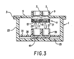
- Figure 3 is a sectional view of an embodiment in accordance with the present invention which includes an upper well-containing plate portion having a composite membrane at the bottom opening of each well and a lower receptacle portion.
- The diagnostic plate employed in accordance with the present invention may have a variety of forms and be made from any suitable material. Preferred materials are thermoplastic resins including polyolefins, such as polypropylene, and polystyrene. The plate may contain as few as one well or as many wells as can be arranged within the plate and effectively serviced by the source of differential pressure, i.e., reduced or positive pressure, employed. Filtration plates currently being used typically have ninety-six wells and this number of wells is not incompatible with the present invention. Typically, the wells in such devices are closely spaced for efficiency and economics. As a result, the potential for cross-talk in such devices is enhanced.
- The wells themselves may be formed in the shape of cylinders projecting upwardly from a base of the plate or, as preferred, may be formed as cylinders projecting downwardly from an upper surface or plane of the plate. Each of the wells may have vertical or downwardly tapered side walls, the latter forming conical or tapered wells.
- The dimensions and shape of each well may be varied depending upon the application of the device. Thus, the well will typically have a cylindrical configuration, but other configurations, such as a square or rectangle, may also be used. Likewise, the diameter of the well may vary considerably depending upon such factors as the size of the sample to be used in each well and whether the device is to be used for diagnostic purposes, its most widespread anticipated application, or for separation and isolation of substances.
- The size of the liquid sample used and, therefore, the dimensions of the well may also depend on the sensitivity of the reaction performed in the well when the device is used for diagnostic purposes. Typically, the diameter of a well will be from 1 mm to 100 mm. Preferably, the diameter of a well will be 2 mm to 25 mm. Typically, the height of a well is 1 mm to 75 mm, preferably 5 mm to 10 mm.
- The bottom of each well has an opening formed therein. For example, the well may have the configuration of an open cylinder or of a hollow truncated or frustoconical cone. The periphery or brim of the opening to which the composite membrane is adhered generally forms a horizontal surface.
- Across the bottom of the well and sealed in liquid-tight relationship to the periphery of the well is a composite membrane. The composite membrane comprises at least three layers. The first or uppermost layer constitutes a "reaction layer" which, when the device in accordance with the present invention is used for diagnostic purposes, is the layer in or upon which reagents are added and tests are performed. This layer may also be used as a filtration medium to separate liquid and solid components when the material retained by the composite membrane is not intended for further characterization. The material from which this layer is formed, like the other layers, must not react adversely with substances found in either the samples, reagents or solvents employed in the analyses. In addition, the reaction layer must be formed from a liquophilic, microporous membrane, typically having an absolute pore rating of 0.001 to 20 microns, preferably 0.02 to 8 microns, and most preferably 0.2 to 3 microns. The reaction layer preferably is also skinless. Materials which are suitable for use as the reaction layer also have voids volumes in the range of 60 to 90 percent, preferably in the range of 75 to 90 percent. Preferred materials are hydrophilic in nature and are, therefore, easily water-wettable and tend to freely pass aqueous solutions. Examples of liquophilic materials which may be used in accordance with the present invention include, but are not limited to, polyamides, such as nylon 66, polyvinylidene difluoride, cellulose esters, and nitrocellulose.
- Liquophilicity, as used herein, refers to the wettability of the membrane by the liquid(s) with which it is contacted. The wettability or liquophilicity of a solid structure, e.g., a membrane, is a function of that structure's critical surface energy and the surface tension of the applied liquid. If the critical surface energy is at least as high as the surface tension of the liquid, the liquid will spontaneously wet the solid structure. For example, a microporous membrane having a critical surface energy of 72 dynes/cm or higher will be wetted by water which has a surface tension of 72 dynes/cm, i.e., it is hydrophilic.
- The capability of a porous structure (membrane) to be wetted by a liquid can be determined by placing a drop of liquid on the porous structure. The angle of contact provides a quantitative measure of wetting. A very high angle of contact indicates poor wetting, while a zero angle of contact defines complete or perfect wetting. Materials used in accordance with the subject invention as the wettable or liquophilic porous layer are characterized by being readily or spontaneously wetted by the applied liquid and have a low angle of contact with the applied liquid. Indeed, when a drop of a test liquid(s) is placed on a spontaneously wettable or liquophilic microporous membrane layer, the drop of liquid penetrates the layer and wets the membrane, effectively providing a zero angle of contact therewith.
- Suitable materials should also be capable of being treated with and retaining or immobilizing a substance being analyzed and/or a reactant which may be used to perform a specified test or reaction with the substance being analyzed for in a sample. The reactant, which may be of ionic, molecular, or macromolecular nature may be immobilized on the reaction layer by strong physical forces or by being bonded in some manner, such as covalent chemical coupling, to the surface of the microporous, liquophilic reaction membrane layer. As employed herein, the term "surface" or "surface area" refers not only to the gross surface(s) of the structure but also, in those cases where a microporous structure such as a membrane is under consideration, to the surfaces of the micropores, i.e., the interior surfaces of the structure which are contacted by fluid during use. As distinguished from "surface area" or "surface", the exposed planar or gross area of the material is herein referred to as the "reaction layer area", "microporous reaction layer area", "reaction layer membrane area", or the like.
- Wettability or liquophilicity is a requisite of the materials used for the microporous reaction layer in accordance with the present invention. It is particularly preferred that such materials be capable of being spontaneously wetted. Some of the materials which are suitable or preferred for use as the reaction layer in accordance with the present invention are intrinsically hydrophilic or water-wettable. Others may be modified to render them hydrophilic. BIODYNE® is an N66 polyamide, microporous membrane commercially available from Pall Corporation which is inherently water-wettable by virtue of its method of manufacture (see U.S. Patent 4,340,479).
- Polyvinylidene fluoride membranes are not inherently water-wettable but can be rendered such by an appropriate surface treatment. Microporous, polyvinylidene fluoride membranes which have been treated to render them hydrophilic are commercially available. As discussed above, wettability or liquophilicity is a function of the critical surface energy of the solid structure and the surface tension of the liquid. Wettability may also be expressed in terms of intrusion pressure which may be defined as the applied pressure required for liquid to penetrate into the pores of the membrane. Although a function of the properties of the liquid used, such as surface tension, materials which are particularly preferred for the reaction layer of the composite membrane have intrusion pressures of or close to zero.
- Materials which are preferred for the reaction layer also have large surface areas. This feature permits a greater amount or higher concentration of reactant to be immobilized in the reaction layer. Accordingly, higher sensitivities may be achieved using the test plate of the present invention.
- Polyamides preferred for use in accordance with the present invention include nylons of the type described in U.S. Patent 4,340,479. Basically, the hydrophilic, microporous, polyamide filter membranes disclosed in U.S. Patent 4,340,479 are membranes prepared from alcohol-insoluble polyamide resins having a methylene to amide ratio in the range of 5:1 to 7:1. Membranes of this group include copolymers of hexamethylene diamine and adipic acid (nylon 66), copolymers of hexamethylene diamine and sebacic acid (nylon 610), homopolymers of poly- -caprolactam (nylon 6), and copolymers of hexamethylene diamine and azelaic acid (nylon 69). As noted above, a membrane material of this description which is particularly useful for the present invention is a microporous, hydrophilic nylon membrane commerically available from Pall Corporation under the trademark BIODYNE®.
- Another preferred membrane useful as the reaction layer is IMMUNODYNE™, available from Pall Corporation. IMMUNODYNE™ is a modified CARBOXYDYNE® membrane, also available from Pall Corporation. CARBOXYDYNE® is a hydrophilic, microporous, skinless nylon 66 membrane with controlled surface properties formed by the cocasting process described in U.S. Patent 4,707,266, as discussed below, specifically by cocasting nylon 66 and a polymer containing an abundance of carboxyl groups to form a membrane having controlled surface properties characterized by carboxyl functional groups at its surfaces. IMMUNODYNE™ membranes may be prepared from CARBOXYDYNE® membranes by treating them with trichloro-s-triazine in the manner described in U.S. Patent 4,693,985, discussed below.
- Also included among the preferred polyamide membranes useful in accordance with the present invention are hydrophilic, microporous, skinless polyamide membranes with controlled surface properties of the type described in (1) U.S. Patent 4,707,266 and in (2) U.S. Patent 4,702,840.
- The hydrophilic, microporous, substantially alcohol-insoluble polyamide membranes with controlled surface properties of these patents are formed by cocasting an alcohol-insoluble polyamide resin with a water-soluble, membrane-surface-modifying polymer having functional polar groups. Like the preferred hydrophilic, microporous nylon membranes which do not have controlled surface-modified polar groups present, the polyamide membranes in accordance with the present invention having controlled surface properties are also skinless; that is, they are characterized by through pores extending from surface-tosurface which are of substantially uniform size and shape. If desired, however, materials having tapered through pores, i.e., pores which are larger at one surface of the sheet, narrowing as they approach the opposite surface of the sheet, may be used.
- The surface-modifying polymers used to prepare the polyamide membranes with controlled surface properties, useful in accordance with the present invention, comprise polymers which contain substantial proportions of chemically functional groups, such as hydroxyl, carboxyl, amine, and imine groups. As a result, the membranes include, at their surfaces, high concentrations of functional groups such as hydroxyl, carboxyl, imine, or a combination of any of the above groups which do not react with one another. These polyamide membranes having controlled surface properties have higher concentrations of carboxyl or imine groups at their surfaces than the preferred microporous, hydrophilic, skinless polyamide membranes described above which do not have controlled surface properties, i.e., those which are formed from the preferred polyamide resin but are not cocast with surface-modifying polymer.
- The reaction layer may be treated by any method known to one of skill in the art to deposit and/or bind reagents thereto. As indicated above, the reagent may be of an ionic, molecular, or macromolecular nature. When used as a diagnostic tool to provide a visible change, the reagent may be one or a combination of substances which is initially colorless and which, upon reaction with a suitable material, provides an optically measurable response. Other possible variations include the use of suitable labels, such as the formation between the deposited reagent and the material for which testing is being conducted of a complex or compound which is appropriately labeled by any known technique, such as enzymatic/substrate labels or the like.
- Although treatment of the reaction layer with a suitable reagent(s) may be performed at the time at which diagnostic tests are to be performed, including addition of the test reagent(s) both immediately preceding and following introduction of the sample containing the analyte to the well(s), the present invention is expected to have greatest application to, and a preferred embodiment includes, a composite membrane in which the reaction layer has been pretreated with at least one test reagent. Typically, pretreatment is conducted after the composite membrane has been sealed to the wells but before the device is shipped to a user. If the reagent(s) is not heat sensitive, the membrane may be treated before assembling the composite membrane.
- A useful method of binding reagents of a molecular nature, especially macromolecules, and particularly those of a biological nature, is disclosed in U.S. Patent 4,693,985. This patent describes a method for immobilizing a wide range of biologically active substances as acceptor molecules on active membranes. The acceptor-bound membranes described in the patent are capable of immobilizing and binding a wide variety of biologically-active compounds, specifically ligands, to the acceptor molecules. Using such reaction layers or membranes permits the testing of bodily fluids, such as blood, serum, plasma, urine, saliva, and the like, and testing for particular substances by chemical assays or immunoassays, such as those where a specific label is employed, such as one indicating enzyme activity or an electromagnetic energy absorbing and/or emitting label, such as a fluoroescent label. The macromolecules used as reagents and bound to the reaction layer or which are assayed for using the device in accordance with the present invention generally include materials of a biological nature and are frequently proteinaceous in nature. The reagent or acceptor molecule bound directly to the reaction layer or the ligand being tested for include such substances as immunoglobulins or antibodies, either polyclonal or monoclonal, antigenic substances, apoproteins, receptors, glycoproteins, lectins, carbohydrates, hormones, enzymes, carrier proteins, heparin, coagulation factors, enzyme substrates, inhibitors, cofactors, nucleic acids, etc.
- Placed below, preferably in intimate contact with or, most preferably, adhered, bonded, or otherwise secured to the reaction layer, particularly at the periphery of each well, is a porous sealing layer which serves several purposes. Strongly preferred for use as a sealing layer is a very porous liquophobic structure. The term "liquophobic" as used herein is effectively the obverse of the term "liquophilic", that is, a liquophobic material has a critical surface energy lower than the surface tension of the applied liquid and is not readily or spontaneously wetted by the applied liquid(s). Liquophobic materials are characterized, then, by a high contact angle between a drop of liquid placed on the surface and the surface. Such a high contact angle indicates poor wetting. The porous sealing layer assists in bonding the reaction layer to the barrier layer. It also makes it possible to form a liquophobic seal at the periphery of the well, thereby eliminating cross-talk by diffusion or wicking. The use of such material in the sealing layer also provides the composite membrane with the ability to withstand or maintain a pressure differential. For example, it prevents, without the application of vacuum or high pressures, penetration of liquid through the composite membrane and the concomitant loss of liquid from the well by dripping. Thus, at specified pressure conditions, generally close to or at atmospheric pressure, liquid is retained within a well. However, when reduced pressure is applied to the downstream side of the composite membrane or super atmospheric pressure is applied to the upstream side of the membrane, liquid readily drains from the well.
- Materials suitable for use as the sealing layer, in addition to being liquophobic, preferably are hydrophobic and are also significantly more porous than the reaction layer. Such material may be present in sheet or fiber form, either woven or unwoven. Suitable materials include polyamides, linear polyesters, such as esters of ethylene glycol and terephthalic acid, polyolefins, such as polypropylene, polyethylene, polymethylpentene, and polyisobutylene, as well as copolymers formed by copolymerizing the monomers used to form the aforementioned homopolymers, such as ethylene-propylene copolymers. Mixtures or blends of such polymers can also be used. The polyolefins are preferred and polypropylene is particularly preferred.
- The third or downstream layer constitutes a barrier layer which, preferably, is in intimate contact with or, most preferably, is adhered, bonded, or otherwise secured to the sealing layer, particularly at the periphery of each well. It is this layer, provided with at least one, and preferably only one, aperture located substantially at the center of the well, which permits a drop of liquid to pass from the well, under application of positive or negative gauge pressure, i.e., super atmospheric pressure applied upstream of the composite membrane or reduced pressure applied downstream of the membrane, and to drop from the plate without radial migration to another well. The apertures can also serve as restriction means, controlling the flow rate of liquid through the composite membrane. Thus, the barrier layer, because of the nature of the material used therein, i.e., a highly liquophobic, preferably hydrophobic, material, enhances isolation between wells and forces the liquid passing through the composite membrane to form small drops at the hole in the barrier layer. These drops, rather than spreading radially when passing through a porous or microporous liquophilic material (such as the material of the reaction layer used alone or in conjunction with the sealing layer) and forming a small contact angle with the surface of such material, tend, when passing through the barrier layer, to form a large contact angle with the surface of liquophobic material. Thus, even if the device is raised at one end so that the bottom surface is not completely horizontal, liquid drops passing through each well tend to drop from the device rather than rolling to one side and potentially contaminating fluid in an adjacent well.
- The size and shape of the apertures formed in the barrier layer depend on a number of variables including the porosity of the barrier layer, the number of apertures in the barrier layer, the porosity and number of apertures formed in the other layers (discussed below), the number of wells, the flow rate sought, ease of manufacturing, etc. However, when a single aperture is used in the barrier layer of each well, it may be formed in a variety of shapes. A suitable size for the aperture is 1/32 to 1/4 inch. An aperture or hole simply formed in the shape of an "X" in the barrier layer, i.e., without a corresponding aperture in the sealing layer or reaction layer, provides an operable system.
- The material used to form the barrier layer should have a greater liquophobicity than either the reaction layer or the sealing layer and may be either microporous or nonporous. Another way of expressing the suitability of a material as the barrier layer relates to the wetting resistance characteristics of the material. A suitable material should be capable of resisting a liquid intrusion pressure greater than the height of the column of liquid above the barrier layer, i.e., the height of the liquid placed in the well. Suitable materials include polyolefins, such as polypropylene, polyhalogenated polyolefins, particularly perfluorinated polyolefins, such as polytetrafluoroethylene, and polyvinylidene difluoride, as well as sulfones. Polytetrafluoroethylene is most preferred.
- In addition to the aperture formed in the liquophobic barrier layer, the reaction layer may also be provided with at least one, and preferably no more than one, aperture. When a single aperture is provided in the reaction layer, the diameter of the aperture may be in the range of 3 to 100 microns. When present as a plurality of apertures, each aperture may have a diameter of 3 to 100 microns. The choice of using a membrane either with or without an aperture in the reaction layer is determined by such factors as the source and type of vacuum or pressure apparatus employed to force a liquid through the composite membrane, the number of wells present in the device, the overall porosity of the composite membrane, the porosity or bubble point characteristics of the reaction layer, and the dimensions of the aperture(s) in the barrier layer. All of these factors affect the rate of fluid flow through the membrane at a given pressure drop.
- The provision of one or more apertures in the reaction layer of the composite membrane in each well assures total voiding of liquid through the composite membrane when positive or negative gauge pressures are employed. When the reaction layer is provided with an aperture, a continuous, rather than an intermittent, application of positive or reduced pressure is necessary since the vacuum or positive pressure will be continuously bleeding away. However, depending on the factors listed above, when a reaction layer having no apertures passing therethrough is provided in the composite membrane, a continuous application of positive or reduced pressure, preferably the latter or a single or intermittent application of positive or negative gauge pressures using, for instance, a syringe and check valve combination may be employed. These latter alternatives are generally preferred.
- In some instances when manufacturing the composite membrane in accordance with the present invention, it is desirable to initially provide each of the layers with the appropriate number of apertures. Thus, a needle(s) may be used to simultaneously form the apertures in each layer in alignment with each other. However, with the porous sealing layer, the aperture will usually not be much larger than the existing pores and when a fibrous material is used, the fibers will generally move back to the position they occupied before insertion of the needle. In this embodiment, the diameters of the apertures in the reaction and barrier layers are the same. This embodiment provides for ease of manufacturing in that the apertures may be formed after the composite membrane is assembled and the layers are secured to one another.
- Typically, reduced pressure or vacuum-assisted fluid flow is accomplished in accordance with the present invention by means of a vacuum manifold which is provided with a means for connection to a vacuum source, such as a projecting tube which can be inserted into vacuum tubing. Such manifolds also include a means to form an air-tight seal between the well(s)-containing diagnostic plate device and the manifold, such as a pliable gasket or the like. Such manifolds commonly include a vertical wall portion, the internal surface of which configurationally conforms to the outer surface of a vertical wall portion of the plate device such that mating of the two wall surfaces occurs. Other designs, however, may be employed, such as the diagnostic plate device being provided with an internal wall surface which mates with an external wall surface of the manifold. Alternative structures in which mating surfaces of the manifold and diagnostic plate device are provided and in which an air-tight seal may be established may also be employed in accordance with the present invention.
- In use, a first test or reagent liquid is normally placed in each of the wells of the diagnostic plate device, and the device is then inserted into the vacuum manifold such that the gasket or sealing means contacts mating surfaces in both the diagnostic plate device and the manifold. Communication between a source of vacuum and the manifold is then established. As the pressure in the manifold decreases, the diagnostic plate device is drawn against the gasket, improving the seal. As this occurs, liquid is drawn through the wells into the vacuum line and to a waste trap. Solutions of samples to be tested or reagents are then introduced into each of the wells.
- To provide a means for isolating and retaining fluids passing through the diagnostic plate device in accordance with the present invention for those situations in which it is desirable to conduct further tests on the liquid, a second modified form of the diagnostic plate device may be used within the vacuum manifold. The modified form of the plate is positioned intermediate the vacuum manifold and the diagnostic plate device in which test samples are analyzed. The modified form of the device is one in which the wells have solid impermeable bottoms, that is, the wells do not have open bottoms covered with the composite membrane in accordance with the present invention but rather the membrane is replaced with the same material from which the walls of the wells are made or some similar material. In most cases, the modified plate is of unitary construction in which the side walls and bottom are formed integrally in a single step. The sealing means is still maintained between the diagnostic plate device in accordance with the present invention and the vacuum manifold when the device is placed into operation.
- In some situations, it may be desirable to use the diagnostic plate device in accordance with the present invention in situations where a vacuum line connected to a centralized source of vacuum or a vacuum pump is not available. An embodiment in accordance with the present invention, nevertheless, permits analysis in such instances. The manifold employed includes a modified outlet means for connecting to a vacuum source. Specifically, the outlet includes a one-way valve of a type generally known to the valve art which permits fluids to be withdrawn from the manifold but does not permit fluids to enter the manifold. In addition, the connection means permits a syringe tip to be inserted into the manifold so that a large syringe may be used as the vacuum source. Such a means for connection to a syringe tip may be a Luer locking device or the like. When a syringe is used as the vacuum source, this will normally be able to displace a much smaller volume of air than will a continuously operating vacuum pump. Accordingly, the vacuum manifold and diagnostic plate device adapted to be used with the manifold will be of a smaller size with fewer than 96 wells which is a typical number for such multiple well diagnostic plate devices.
- As with the larger diagnostic plate device described above, the periphery of the plate may have any suitable configuration as long as adequate mating and sealing surfaces are provided between the manifold and the diagnostic plate device. To sufficiently reduce the volume of the manifold when the device is to be used with a syringe as the source of vacuum, the periphery of the plate is preferred to have a circular configuration, such as that shown in Figure 1, the wells also preferably being arranged in a circular configuration. With such a configuration, various means may be provided for the attachment of the plate to the manifold including that described above in which the well-containing plate is merely pressed into the manifold with a sealing means separating two mating surfaces. Alternatively, in addition to sealing means, threading or bayonet mounts may be provided on corresponding mating surfaces of the plate and manifold. However, a preferred structure is one that is disposable in which the diagnostic plate is formed integrally with the manifold. Preferably, the integrally formed structure also includes a means for trapping liquids in the manifold. With this structure, possibly contaminated fluids are trapped within the device, and the entire article, including trapped liquids, could be disposed of while minimizing risks associated with contamination.
- Figures 1 to 3 illustrate preferred embodiments in accordance with the present invention. As shown in Figures 1 and 2, the device is formed from a multi-well diagnostic plate or
plate portion 1 and a vacuum manifold ormanifold portion 3. In one of the preferred embodiments in accordance with the present invention, theelements diagnostic plate portion 1 is not detachable from themanifold portion 3. This embodiment is intended to be disposable. Other than this feature and the vacuum connecting means, the embodiments are substantially similar in most respects. Thus, thediagnostic plate portion 1 is provided with an upper ortop wall 5 having located therein one or more wells 7. The wells are defined by awall portion 9 which is preferably vertical or substantially vertical, although the wall portion may have a downward taper. The well is provided with openings at both the top and bottom ends. Sealed to the bottom end 19 of the well iscomposite membrane 11 formed from anupper reaction layer 13, abottom barrier layer 15 having anaperture 29 passing therethrough, and asealing layer 17 located intermediate thereaction layer 13 and thebarrier layer 15. As a result of the heat process used, a dense, somewhat compacted,liquophobic zone 21 is provided at the periphery of each well which prevents lateral flow or "cross-talk" of fluids, particularly liquids, between wells. - The
manifold portion 3 comprises a side wall orwalls 23 andbottom wall 25. The upper plate orwall 5,side wall 23, andbottom wall 25 define a housing in which the wells are located. A vacuum connection means 27 is provided to communicate the housing or manifold portion with a source of vacuum (not shown). - One preferred purpose of the
sealing layer 17 is to seal thebarrier layer 15 to thereaction layer 13. Another function served by the sealing layer is to provide a liquophobic seal at the periphery or rim of each well where the composite membrane is secured to the periphery of the opening at the bottom of the well. Such a seal is typically accomplished by means of a heat, and preferably combined with pressure, treatment. Heat-sealing methods using radiant heat or ultrasonic sealing techniques with apparatus, such as heater blocks or welding horns, respectively, may be employed. It is the liquophobic seal formed at the periphery of the opening of each well by such treatment which prevents liquid passing through the composite membrane from diffusing or migrating radially and possibly contaminating another well. - The embodiment in accordance with the present invention illustrated in Figure 3 permits liquid which has passed through a well of a diagnostic plate in accordance with the present invention, such as that described above, to be isolated from a test sample and retained. In this embodiment, the reference numerals common to Figure 3, and Figures 1 and 2, describe substantially the same elements. The major distinction to be drawn between the embodiment in accordance with the present invention illustrated in Figures 1 and 2 and that of Figure 3 is the inclusion within the
manifold portion 3 of a second or receivingplate 31 having aplate portion 35 with one ormore wells 37 located therein, each well defined by awall portion 39. The dimensions and configurations of theplate portion 31,top wall 35,wells 37, andwall portion 39 are preferably the same or similar to those of the correspondingtop wall 5, wells 7, andwall portions 9 of thediagnostic plate portion 1. The major difference between the upperdiagnostic plate portion 1 and the second plate orreceptacle 31 is that the latter substitutes a solid impermeable bottom 41 for thecomposite membrane 11 of the former. Thereceptacle plate 31 is arranged within themanifold 3 in such a manner that the second plate (and particularly the well(s) 37 located therein) is aligned with and in liquid receiving relationship to the first plate (and particularly the wells 7 located in the diagnostic plate 1). This permits liquid passing through each one of the wells 7 in the diagnostic plate to be isolated from an adjacent well and, after passing through thecomposite membrane 11, to be retained in a solid bottom well 41 of thesecond plate 31 corresponding to the well in the upper plate through which it just passed. - The composite membrane in accordance with the present invention may be assembled by a variety of techniques. Thus, each of the separate layers may be overlaid and the separate layers sealed to one another and to the bottom of each well in a single heat-sealing procedure. This may be accomplished by superposing the individual layers, i.e., the reaction layer, the sealing layer, and the barrier layer, over the open bottom ends of the wells such that the apertures in the barrier layer and, where appropriate, other layers are located substantially at the centers of each well. Heat is then applied from the barrier layer side of the membrane to secure the separate layers to one another and also to form a hydrophobic seal between the composite membrane and the bottom edge surface of the wall of each well. Heat is applied either directly in the form of radiant heat by a heater block or as ultrasonic energy using a welding horn. In this manner, the reaction layer is sealed to the edges of each of the wells and, simultaneously, the sealing layer fuses the reaction layer to the barrier layer.
- To facilitate handling of the layers of material forming the composite membrane, rather than superpose each layer individually over the bottoms of the wells, it is preferred that the edges of the sheets of material forming the layers may be welded or tacked to one another to provide a preliminary composite membrane. The sealing of the composite structure to the bottom edge surfaces of the wells and possibly of the layers to each other occurring, as indicated above, when heat is applied to the layers of material superposed on the plate.
- Alternatively, although less preferred, rather than adhering the edges of the separate sheets such as by tacking or the like, the three layers may be secured to one another to form the composite membrane in a first step and the formation of a liquid-tight seal to the bottom of the wells may be achieved in a second step. Other alternatives include bonding the sealing layer to the reaction layer in a first step, such as that described in U.S. Patent Application Serial Number 685,042, filed December 21, 1984, and incorporated herein by reference. According to this method, microfibers are directed in a stream toward a sheet of the reaction layer, generally after the fibers are extruded from a fiberizing die and attenuated in one or more gas streams. The microfibers are extruded at an elevated temperature and after contacting the microporous reaction layer are cooled to form a composite, two layer membrane containing a web of microfibers as a sealing layer secured to the reaction layer. A similar procedure may be employed in which the sealing layer is formed as a sheet and, while at an elevated temperature, is placed in contact with a sheet of the microporous reaction layer. The hydrophobic barrier layer is then applied to the two layer composite membrane by a heat bonding procedure.
- In use, a solution containing the sample to be analyzed and one or more reagent solutions may be added simultaneously or, in most instances, preferably, sequentially to each well of the multiple well diagnostic plate. Under appropriate temperature conditions, the solutions are added to and removed from each well, in timed sequence to allow sufficient time for reactions to take place in solution or on the surface of the reaction layer before the addition or removal, as appropriate, of a solution. In many instances, molecular species, particularly macromolecular species, such as nucleic acids, antibodies, antigens, or enzyme-labelled conjugates are adsorbed. Weakly or non-adsorbed molecules are removed from the surface of the composite membrane by washing between steps with suitable buffers. When the reaction sequence is completed, a labelled product, such as a visible colored or fluorescent product, remains or is formed on the surface of the membrane within the well.
- To perform quantitative assays, the well(s)-containing plates are placed in a suitable reading device, typically containing a source and a detector of radiation. The colored or light emitting product may then be quantitatively measured using either transmitted or reflected light.
- Solutions may be introduced to the well using a pipette. However, after a suitable period for reaction to occur, the solutions may be removed by application of vacuum or elevated pressure. Furthermore, in some instances, it may be unnecessary to remove one solution completely before the addition of another solution. Rather, one solution may be added as the previous solution is being removed or, in some instances, a second solution may be added while the first is still present and the two solutions allowed to mix before removal.
Claims (13)
Applications Claiming Priority (2)
| Application Number | Priority Date | Filing Date | Title |
|---|---|---|---|
| US06/941,386 US4797259A (en) | 1986-12-15 | 1986-12-15 | Well-type diagnostic plate device |
| US941386 | 1997-09-30 |
Publications (3)
| Publication Number | Publication Date |
|---|---|
| EP0272043A2 true EP0272043A2 (en) | 1988-06-22 |
| EP0272043A3 EP0272043A3 (en) | 1989-04-05 |
| EP0272043B1 EP0272043B1 (en) | 1992-06-24 |
Family
ID=25476389
Family Applications (1)
| Application Number | Title | Priority Date | Filing Date |
|---|---|---|---|
| EP87310827A Expired EP0272043B1 (en) | 1986-12-15 | 1987-12-09 | Diagnostic device |
Country Status (6)
| Country | Link |
|---|---|
| US (1) | US4797259A (en) |
| EP (1) | EP0272043B1 (en) |
| JP (1) | JPH0664062B2 (en) |
| CA (1) | CA1312265C (en) |
| DE (1) | DE3780012T2 (en) |
| GB (1) | GB2198847B (en) |
Cited By (16)
| Publication number | Priority date | Publication date | Assignee | Title |
|---|---|---|---|---|
| EP0310406A2 (en) * | 1987-10-01 | 1989-04-05 | E-Y Laboratories, Inc. | Directed flow diagnostic device and method |
| WO1990009588A1 (en) * | 1989-02-09 | 1990-08-23 | Eastman Kodak Company | Immunoassay kit containing multiple level filter |
| EP0418765A2 (en) * | 1989-09-21 | 1991-03-27 | Becton, Dickinson and Company | Test device including flow control means |
| DE19514521A1 (en) * | 1995-04-12 | 1996-10-17 | Schulz Hans Joachim Dr | Laboratory equipment for simultaneous manual performance of chemical reactions |
| WO1996039250A1 (en) * | 1995-06-05 | 1996-12-12 | Millipore Investment Holdings Limited | Multiple sample filtration device |
| WO2000066268A2 (en) * | 1999-05-05 | 2000-11-09 | Millipore Corporation | Well(s) containing filtration devices |
| WO2001019504A2 (en) * | 1999-09-17 | 2001-03-22 | Millipore Corporation | Three dimensional patterned porous structures |
| WO2001019502A2 (en) * | 1999-09-17 | 2001-03-22 | Millipore Corporation | High throughput screening card |
| WO2001019505A2 (en) * | 1999-09-17 | 2001-03-22 | Millipore Corporation | Patterned porous structures |
| WO2001096018A2 (en) * | 2000-06-13 | 2001-12-20 | Symyx Technologies, Inc. | Apparatus and method for evaluating a test fluid |
| EP1333282A2 (en) * | 2002-02-01 | 2003-08-06 | Fuji Photo Film Co., Ltd. | Method and reactor for conducting receptor-ligand association reactions |
| US6662635B2 (en) | 2000-06-13 | 2003-12-16 | Symyx Technologies, Inc. | Method for evaluating a test fluid |
| EP1439897A2 (en) * | 2001-10-11 | 2004-07-28 | Aviva Biosciences Corporation | Methods, compositions, and automated systems for separating rare cells from fluid samples |
| US6878344B2 (en) | 2000-06-13 | 2005-04-12 | Symyx Technologies, Inc. | Apparatus for testing compositions in contact with a porous medium |
| FR2868046A1 (en) * | 2004-03-24 | 2005-09-30 | Rexam Pharma Soc Par Actions S | Liquid container and dispenser has hydrophile and hydrophobe filtration membranes inside neck or container |
| WO2009006660A1 (en) * | 2007-07-06 | 2009-01-15 | Technoclone Gesellschaft M.B.H. | Plasma filtration |
Families Citing this family (103)
| Publication number | Priority date | Publication date | Assignee | Title |
|---|---|---|---|---|
| US5137691A (en) * | 1987-01-27 | 1992-08-11 | V-Tech, Inc. | Antibody testing system with removable air gap |
| US5419870A (en) * | 1987-01-27 | 1995-05-30 | V-Tech, Inc. | Antibody testing system |
| US4902481A (en) * | 1987-12-11 | 1990-02-20 | Millipore Corporation | Multi-well filtration test apparatus |
| US5035866A (en) * | 1988-02-16 | 1991-07-30 | Wannlund Jon C | Luminescence reaction test apparatus |
| US4908319A (en) * | 1988-03-16 | 1990-03-13 | Smyczek Peter J | Laboratory apparatus |
| US5100775A (en) * | 1988-03-16 | 1992-03-31 | Smyczek Peter J | Method for conducting nucleic acid hybridization in chamber with precise fluid delivery |
| US5281540A (en) * | 1988-08-02 | 1994-01-25 | Abbott Laboratories | Test array for performing assays |
| US4959197A (en) * | 1988-09-07 | 1990-09-25 | Bio-Rad Laboratories, Inc. | Filter canister for immunoassays |
| JPH062142Y2 (en) * | 1988-11-22 | 1994-01-19 | 株式会社ニッショー | Urine collection test equipment |
| US4927604A (en) * | 1988-12-05 | 1990-05-22 | Costar Corporation | Multiwell filter plate vacuum manifold assembly |
| US5200312A (en) * | 1989-01-30 | 1993-04-06 | The United States Of America As Represented By The Secretary Of The Navy | Membrane based dot immunoassay and method of use |
| US5219101A (en) * | 1989-06-01 | 1993-06-15 | Pall Corporation | Contamination-resistant dispensing and metering drop forming device |
| US5265770A (en) * | 1989-06-01 | 1993-11-30 | Pall Corporation | Contamination-resistant dispensing and metering device |
| US5085986A (en) * | 1989-06-14 | 1992-02-04 | Eastman Kodak Company | Diagnostic test kit and method for determination of chlamydial antigen using a membrane having surface hydroxy groups |
| GB2243446B (en) * | 1990-04-25 | 1994-05-25 | Pfizer Ltd | An assay tray and assembly |
| US5039493A (en) * | 1990-05-04 | 1991-08-13 | The United States Of America As Represented By The Secretary Of The Navy | Positive pressure blotting apparatus with hydropholic filter means |
| US5116496A (en) * | 1991-03-19 | 1992-05-26 | Minnesota Mining And Manufacturing Company | Membrane-containing wells for microtitration and microfiltration |
| US5227137A (en) * | 1991-04-04 | 1993-07-13 | Nicholson Precision Instruments Inc. | Vacuum clamped multi-sample filtration apparatus |
| EP0582638A1 (en) * | 1991-04-04 | 1994-02-16 | Nicholson Precision Instruments; Inc. | A vacuum clamped multi-sample filtration apparatus and method |
| US5188733A (en) * | 1992-02-26 | 1993-02-23 | Trustees Of Boston University | Apparatus and process for effecting sequential peptide syntheses |
| US20030211555A1 (en) * | 1992-07-10 | 2003-11-13 | Jaffe Russell M. | Assay for evaluation of cellular response to allergens |
| US5543047A (en) | 1992-11-06 | 1996-08-06 | Pall Corporation | Filter with over-laid pleats in intimate contact |
| US5462874A (en) * | 1993-06-23 | 1995-10-31 | Wolf; Martin L. | Dialyzed multiple well tissue culture plate |
| US6893816B1 (en) * | 1993-10-28 | 2005-05-17 | Houston Advanced Research Center | Microfabricated, flowthrough porous apparatus for discrete detection of binding reactions |
| US5487872A (en) * | 1994-04-15 | 1996-01-30 | Molecular Device Corporation | Ultraviolet radiation transparent multi-assay plates |
| US5514343A (en) * | 1994-06-22 | 1996-05-07 | Nunc, As | Microtitration system |
| US7166470B2 (en) * | 1994-10-18 | 2007-01-23 | Symyx Technologies, Inc. | Formation of combinatorial arrays of materials using solution-based methodologies |
| US6171555B1 (en) | 1995-04-17 | 2001-01-09 | Ontogen Corporation | Reaction block docking station |
| US5609826A (en) * | 1995-04-17 | 1997-03-11 | Ontogen Corporation | Methods and apparatus for the generation of chemical libraries |
| US5833860A (en) * | 1995-08-28 | 1998-11-10 | Millipore Investment Holdings Limited | Centrifugal adsorptive sample preparation device and method |
| US6852289B2 (en) * | 1996-10-02 | 2005-02-08 | Saftest, Inc. | Methods and apparatus for determining analytes in various matrices |
| US5958714A (en) * | 1996-10-02 | 1999-09-28 | Safety Associates, Inc. | Test kits for determining at least two specific analytes in foods and other complex matrices |
| US6274094B1 (en) | 1997-01-13 | 2001-08-14 | Weller, Iii Harold Norris | Nestable, modular apparatus for synthesis of multiple organic compounds |
| US6057165A (en) * | 1997-02-07 | 2000-05-02 | Becton, Dickinson And Company | Quality control procedure for membrane flow-through diagnostic assay devices |
| US6426050B1 (en) | 1997-05-16 | 2002-07-30 | Aurora Biosciences Corporation | Multi-well platforms, caddies, lids and combinations thereof |
| US6063338A (en) | 1997-06-02 | 2000-05-16 | Aurora Biosciences Corporation | Low background multi-well plates and platforms for spectroscopic measurements |
| US6171780B1 (en) | 1997-06-02 | 2001-01-09 | Aurora Biosciences Corporation | Low fluorescence assay platforms and related methods for drug discovery |
| US5910287A (en) * | 1997-06-03 | 1999-06-08 | Aurora Biosciences Corporation | Low background multi-well plates with greater than 864 wells for fluorescence measurements of biological and biochemical samples |
| US6229603B1 (en) | 1997-06-02 | 2001-05-08 | Aurora Biosciences Corporation | Low background multi-well plates with greater than 864 wells for spectroscopic measurements |
| US6517781B1 (en) | 1997-06-02 | 2003-02-11 | Aurora Biosciences Corporation | Low fluorescence assay platforms and related methods for drug discovery |
| US6194160B1 (en) * | 1998-03-19 | 2001-02-27 | Immunetics, Inc. | Systems and methods for rapid blot screening |
| US5961925A (en) | 1997-09-22 | 1999-10-05 | Bristol-Myers Squibb Company | Apparatus for synthesis of multiple organic compounds with pinch valve block |
| GB9800933D0 (en) * | 1998-01-17 | 1998-03-11 | Central Research Lab Ltd | A dispenser |
| US6565813B1 (en) * | 1998-02-04 | 2003-05-20 | Merck & Co., Inc. | Virtual wells for use in high throughput screening assays |
| US6184040B1 (en) | 1998-02-12 | 2001-02-06 | Polaroid Corporation | Diagnostic assay system and method |
| US6861035B2 (en) | 1998-02-24 | 2005-03-01 | Aurora Discovery, Inc. | Multi-well platforms, caddies, lids and combinations thereof |
| US6825042B1 (en) * | 1998-02-24 | 2004-11-30 | Vertex Pharmaceuticals (San Diego) Llc | Microplate lid |
| ATE308383T1 (en) * | 1998-02-27 | 2005-11-15 | Pall Corp | DEVICES FOR SAMPLE PREPARATION |
| US6331715B1 (en) | 1998-10-14 | 2001-12-18 | Polaroid Corporation | Diagnostic assay system and method having a luminescent readout signal |
| US6495373B1 (en) | 1998-10-14 | 2002-12-17 | Polaroid Corporation | Method and apparatus for performing diagnostic tests |
| US6555060B1 (en) | 1998-10-14 | 2003-04-29 | Polaroid Corporation | Apparatus for performing diagnostic testing |
| US6432358B2 (en) | 1999-01-27 | 2002-08-13 | Polaroid Corporation | Diagnostic assay device |
| US6328930B1 (en) | 1999-02-11 | 2001-12-11 | Polaroid Corporation | Apparatus for performing diagnostic testing |
| US6635430B1 (en) * | 1999-07-16 | 2003-10-21 | Dupont Pharmaceuticals Company | Filtrate plate device and reversible-well plate device |
| US6869572B1 (en) * | 1999-09-13 | 2005-03-22 | Millipore Corporation | High density cast-in-place sample preparation card |
| US6383748B1 (en) * | 1999-09-14 | 2002-05-07 | Pamgene B.V. | Analytical test device with substrate having oriented through going channels and improved methods and apparatus for using same |
| US6893562B2 (en) * | 2000-05-05 | 2005-05-17 | Millipore Corporation | Underdrain for filtration membrane |
| ES2331108T3 (en) * | 2000-05-18 | 2009-12-22 | Millipore Corporation | MULTIPLE WELL PLATE WITH ADHESIVE ADHESIVE FILTER. |
| US6676904B1 (en) * | 2000-07-12 | 2004-01-13 | Us Gov Sec Navy | Nanoporous membrane immunosensor |
| US6641782B1 (en) | 2000-11-15 | 2003-11-04 | Polaroid Corporation | Apparatus for performing diagnostic testing |
| US6521188B1 (en) * | 2000-11-22 | 2003-02-18 | Industrial Technology Research Institute | Microfluidic actuator |
| EP1346208A2 (en) * | 2000-11-28 | 2003-09-24 | Nanogen, Inc. | Microtiter plate format device and methods for separating differently charged molecules using an electric field |
| SE0102921D0 (en) * | 2001-08-30 | 2001-08-30 | Astrazeneca Ab | Pharmaceutically useful compounds |
| EP1217375A1 (en) * | 2000-12-20 | 2002-06-26 | Direvo Biotech AG | Solid phase substrate for structured reaction substrates |
| US6491873B2 (en) * | 2001-01-23 | 2002-12-10 | Varian, Inc. | Multi-well filtration apparatus |
| US7413910B2 (en) * | 2001-03-08 | 2008-08-19 | Exelixis, Inc. | Multi-well apparatus |
| KR20040068467A (en) * | 2001-05-31 | 2004-07-31 | 폴 코포레이션 | Well for processing a fluid |
| EP1427515B1 (en) * | 2001-09-20 | 2007-08-08 | Millipore Corporation | Process for making a fluid processing module |
| JP4117249B2 (en) * | 2001-10-15 | 2008-07-16 | バイオセプト インコーポレイテッド | Microwell biochip |
| US6716350B2 (en) | 2002-05-03 | 2004-04-06 | Millipore Corporation | Microplate protective tray undercover |
| US7211224B2 (en) * | 2002-05-23 | 2007-05-01 | Millipore Corporation | One piece filtration plate |
| US7122155B2 (en) * | 2002-07-16 | 2006-10-17 | Mcgill University | Electron microscopy cell fraction sample preparation robot |
| US7128878B2 (en) * | 2002-10-04 | 2006-10-31 | Becton, Dickinson And Company | Multiwell plate |
| US20040210036A1 (en) * | 2003-04-15 | 2004-10-21 | Nanogen, Inc. | Peptide substrate libraries |
| DE102008050750A1 (en) * | 2008-10-06 | 2010-04-08 | Universtität Leipzig Forschungskontaktstelle | Modular system for method-oriented assembly of functional units for mixing, processing and / or separating samples for use in biological / medical research and for diagnostics |
| US8986404B2 (en) | 2009-11-03 | 2015-03-24 | Societe Bic | Gas generator with starter mechanism and catalyst shield |
| JP5631324B2 (en) * | 2008-11-03 | 2014-11-26 | ソシエテ ビックSociete Bic | Gas generator |
| US8636826B2 (en) * | 2009-11-03 | 2014-01-28 | Societe Bic | Hydrogen membrane separator |
| CN102365239B (en) * | 2009-03-27 | 2014-05-28 | Pur水纯化产品公司 | Droplet forming fluid treatment devices and methods of forming filtered droplets in a fluid treatment device |
| GB0913258D0 (en) | 2009-07-29 | 2009-09-02 | Dynex Technologies Inc | Reagent dispenser |
| US9523701B2 (en) | 2009-07-29 | 2016-12-20 | Dynex Technologies, Inc. | Sample plate systems and methods |
| JP5515636B2 (en) * | 2009-10-30 | 2014-06-11 | Tdk株式会社 | Collection instrument, detection device, and collection method |
| US20110104026A1 (en) * | 2009-11-05 | 2011-05-05 | Seongjun Yoon | Apparatus for extracting biochemical materials from biological samples |
| US20110143378A1 (en) * | 2009-11-12 | 2011-06-16 | CyVek LLC. | Microfluidic method and apparatus for high performance biological assays |
| US9651568B2 (en) | 2009-11-23 | 2017-05-16 | Cyvek, Inc. | Methods and systems for epi-fluorescent monitoring and scanning for microfluidic assays |
| US9700889B2 (en) | 2009-11-23 | 2017-07-11 | Cyvek, Inc. | Methods and systems for manufacture of microarray assay systems, conducting microfluidic assays, and monitoring and scanning to obtain microfluidic assay results |
| JP5701894B2 (en) | 2009-11-23 | 2015-04-15 | サイヴェク・インコーポレイテッド | Method and apparatus for performing an assay |
| US10065403B2 (en) | 2009-11-23 | 2018-09-04 | Cyvek, Inc. | Microfluidic assay assemblies and methods of manufacture |
| US9759718B2 (en) | 2009-11-23 | 2017-09-12 | Cyvek, Inc. | PDMS membrane-confined nucleic acid and antibody/antigen-functionalized microlength tube capture elements, and systems employing them, and methods of their use |
| US9855735B2 (en) | 2009-11-23 | 2018-01-02 | Cyvek, Inc. | Portable microfluidic assay devices and methods of manufacture and use |
| US9500645B2 (en) | 2009-11-23 | 2016-11-22 | Cyvek, Inc. | Micro-tube particles for microfluidic assays and methods of manufacture |
| WO2012092242A2 (en) | 2010-12-29 | 2012-07-05 | 3M Innovative Properties Company | Microbial detection article having a water-absorbent filter assembly |
| US9372148B2 (en) | 2011-02-09 | 2016-06-21 | The Boeing Company | Bond surface testing apparatus and method |
| US8616050B1 (en) * | 2011-02-09 | 2013-12-31 | The Boeing Company | Bond surface testing apparatus and method |
| CN106552682B (en) | 2011-03-22 | 2020-06-19 | 西维克公司 | Microfluidic device and methods of manufacture and use |
| JP5659960B2 (en) * | 2011-06-09 | 2015-01-28 | コニカミノルタ株式会社 | Cell plane development method |
| EP2604342B1 (en) * | 2011-12-12 | 2014-06-25 | ibidi GmbH | Sample chamber with partition board |
| KR102114734B1 (en) | 2012-03-08 | 2020-05-25 | 싸이벡, 아이엔씨 | Micro-tube particles for microfluidic assays and methods of manufacture |
| FR2991689B1 (en) | 2012-06-11 | 2018-04-20 | Diagast | IMMUNO-HEMATOLOGICAL DIAGNOSTIC DEVICE AND USES |
| US9568404B2 (en) | 2014-05-16 | 2017-02-14 | Junyu Mai | Method and apparatus for biomolecule analysis |
| US10228367B2 (en) | 2015-12-01 | 2019-03-12 | ProteinSimple | Segmented multi-use automated assay cartridge |
| CN112204398A (en) | 2018-02-16 | 2021-01-08 | 迪亚加斯特公司 | In vitro diagnostic device comprising beads and uses thereof |
| FR3093651A1 (en) | 2019-03-15 | 2020-09-18 | Seigniory Chemical Products Ltd. - Produits Chimiques Seigneurie Ltee | SYSTEM AND METHOD FOR FILTERING SAMPLES FROM CONTAINERS |
Citations (8)
| Publication number | Priority date | Publication date | Assignee | Title |
|---|---|---|---|---|
| WO1982003690A1 (en) * | 1981-04-10 | 1982-10-28 | Bjoerkman Rune | Apparatus for carrying out separation step in analyses,eg.in radioimmunoassays |
| EP0098534A1 (en) * | 1982-07-01 | 1984-01-18 | Millipore Corporation | Filter apparatus |
| US4427415A (en) * | 1979-01-05 | 1984-01-24 | Cleveland Patrick H | Manifold vacuum biochemical test method and device |
| US4493815A (en) * | 1983-07-28 | 1985-01-15 | Bio-Rad Laboratories, Inc. | Supporting and filtering biochemical test plate assembly |
| EP0131934A2 (en) * | 1983-07-15 | 1985-01-23 | Baxter Diagnostics Inc. | An assay cartridge |
| EP0154839A2 (en) * | 1984-02-29 | 1985-09-18 | Bayer Ag | Test device and method for the detection of a component of a fluid sample |
| EP0185373A2 (en) * | 1984-12-21 | 1986-06-25 | Pall Corporation | Supported microporous membrane and method of making |
| WO1987006608A1 (en) * | 1986-04-25 | 1987-11-05 | Digital Diagnostics | Manifold vacuum device for chemical, biochemical, and immunological uses |
Family Cites Families (6)
| Publication number | Priority date | Publication date | Assignee | Title |
|---|---|---|---|---|
| CA1056746A (en) * | 1974-09-06 | 1979-06-19 | Chung J. Lai | Biologically active membrane material |
| US4090850A (en) * | 1976-11-01 | 1978-05-23 | E. R. Squibb & Sons, Inc. | Apparatus for use in radioimmunoassays |
| US4407943A (en) * | 1976-12-16 | 1983-10-04 | Millipore Corporation | Immobilized antibody or antigen for immunoassay |
| US4246339A (en) * | 1978-11-01 | 1981-01-20 | Millipore Corporation | Test device |
| US4317726A (en) * | 1981-02-12 | 1982-03-02 | The United States Of America As Represented By The Secretary Of The Army | Microbial filter assembly |
| US4948442A (en) * | 1985-06-18 | 1990-08-14 | Polyfiltronics, Inc. | Method of making a multiwell test plate |
-
1986
- 1986-12-15 US US06/941,386 patent/US4797259A/en not_active Expired - Lifetime
-
1987
- 1987-12-09 GB GB8728754A patent/GB2198847B/en not_active Expired - Fee Related
- 1987-12-09 DE DE8787310827T patent/DE3780012T2/en not_active Expired - Fee Related
- 1987-12-09 EP EP87310827A patent/EP0272043B1/en not_active Expired
- 1987-12-14 CA CA000554231A patent/CA1312265C/en not_active Expired - Fee Related
- 1987-12-15 JP JP62317291A patent/JPH0664062B2/en not_active Expired - Lifetime
Patent Citations (8)
| Publication number | Priority date | Publication date | Assignee | Title |
|---|---|---|---|---|
| US4427415A (en) * | 1979-01-05 | 1984-01-24 | Cleveland Patrick H | Manifold vacuum biochemical test method and device |
| WO1982003690A1 (en) * | 1981-04-10 | 1982-10-28 | Bjoerkman Rune | Apparatus for carrying out separation step in analyses,eg.in radioimmunoassays |
| EP0098534A1 (en) * | 1982-07-01 | 1984-01-18 | Millipore Corporation | Filter apparatus |
| EP0131934A2 (en) * | 1983-07-15 | 1985-01-23 | Baxter Diagnostics Inc. | An assay cartridge |
| US4493815A (en) * | 1983-07-28 | 1985-01-15 | Bio-Rad Laboratories, Inc. | Supporting and filtering biochemical test plate assembly |
| EP0154839A2 (en) * | 1984-02-29 | 1985-09-18 | Bayer Ag | Test device and method for the detection of a component of a fluid sample |
| EP0185373A2 (en) * | 1984-12-21 | 1986-06-25 | Pall Corporation | Supported microporous membrane and method of making |
| WO1987006608A1 (en) * | 1986-04-25 | 1987-11-05 | Digital Diagnostics | Manifold vacuum device for chemical, biochemical, and immunological uses |
Cited By (28)
| Publication number | Priority date | Publication date | Assignee | Title |
|---|---|---|---|---|
| EP0310406A3 (en) * | 1987-10-01 | 1990-11-22 | E-Y Laboratories, Inc. | Directed flow diagnostic device and method |
| EP0310406A2 (en) * | 1987-10-01 | 1989-04-05 | E-Y Laboratories, Inc. | Directed flow diagnostic device and method |
| WO1990009588A1 (en) * | 1989-02-09 | 1990-08-23 | Eastman Kodak Company | Immunoassay kit containing multiple level filter |
| EP0418765A2 (en) * | 1989-09-21 | 1991-03-27 | Becton, Dickinson and Company | Test device including flow control means |
| EP0418765A3 (en) * | 1989-09-21 | 1992-08-19 | Becton Dickinson And Company | Test device including flow control means |
| DE19514521A1 (en) * | 1995-04-12 | 1996-10-17 | Schulz Hans Joachim Dr | Laboratory equipment for simultaneous manual performance of chemical reactions |
| WO1996039250A1 (en) * | 1995-06-05 | 1996-12-12 | Millipore Investment Holdings Limited | Multiple sample filtration device |
| WO2000066268A3 (en) * | 1999-05-05 | 2001-08-02 | Millipore Corp | Well(s) containing filtration devices |
| WO2000066268A2 (en) * | 1999-05-05 | 2000-11-09 | Millipore Corporation | Well(s) containing filtration devices |
| US6309605B1 (en) | 1999-05-05 | 2001-10-30 | Millipore Corporation | Well(s) containing filtration devices |
| WO2001019505A3 (en) * | 1999-09-17 | 2001-08-09 | Millipore Corp | Patterned porous structures |
| US6627291B1 (en) | 1999-09-17 | 2003-09-30 | Millipore Corporation | Three dimensional patterned porous structures |
| WO2001019504A3 (en) * | 1999-09-17 | 2001-08-02 | Millipore Corp | Three dimensional patterned porous structures |
| WO2001019502A3 (en) * | 1999-09-17 | 2001-08-09 | Millipore Corp | High throughput screening card |
| WO2001019502A2 (en) * | 1999-09-17 | 2001-03-22 | Millipore Corporation | High throughput screening card |
| WO2001019504A2 (en) * | 1999-09-17 | 2001-03-22 | Millipore Corporation | Three dimensional patterned porous structures |
| WO2001019505A2 (en) * | 1999-09-17 | 2001-03-22 | Millipore Corporation | Patterned porous structures |
| WO2001096018A3 (en) * | 2000-06-13 | 2002-08-29 | Symyx Technologies Inc | Apparatus and method for evaluating a test fluid |
| WO2001096018A2 (en) * | 2000-06-13 | 2001-12-20 | Symyx Technologies, Inc. | Apparatus and method for evaluating a test fluid |
| US6662635B2 (en) | 2000-06-13 | 2003-12-16 | Symyx Technologies, Inc. | Method for evaluating a test fluid |
| US6878344B2 (en) | 2000-06-13 | 2005-04-12 | Symyx Technologies, Inc. | Apparatus for testing compositions in contact with a porous medium |
| EP1439897A2 (en) * | 2001-10-11 | 2004-07-28 | Aviva Biosciences Corporation | Methods, compositions, and automated systems for separating rare cells from fluid samples |
| EP1439897A4 (en) * | 2001-10-11 | 2006-03-08 | Aviva Biosciences Corp | Methods, compositions, and automated systems for separating rare cells from fluid samples |
| EP2156879A3 (en) * | 2001-10-11 | 2010-07-07 | Aviva Biosciences Corporation | Methods, compositions and automated systems for separating rare cells from fluid samples |
| EP1333282A2 (en) * | 2002-02-01 | 2003-08-06 | Fuji Photo Film Co., Ltd. | Method and reactor for conducting receptor-ligand association reactions |
| EP1333282A3 (en) * | 2002-02-01 | 2003-12-03 | Fuji Photo Film Co., Ltd. | Method and reactor for conducting receptor-ligand association reactions |
| FR2868046A1 (en) * | 2004-03-24 | 2005-09-30 | Rexam Pharma Soc Par Actions S | Liquid container and dispenser has hydrophile and hydrophobe filtration membranes inside neck or container |
| WO2009006660A1 (en) * | 2007-07-06 | 2009-01-15 | Technoclone Gesellschaft M.B.H. | Plasma filtration |
Also Published As
| Publication number | Publication date |
|---|---|
| EP0272043A3 (en) | 1989-04-05 |
| EP0272043B1 (en) | 1992-06-24 |
| DE3780012T2 (en) | 1993-01-21 |
| JPH0664062B2 (en) | 1994-08-22 |
| US4797259A (en) | 1989-01-10 |
| GB8728754D0 (en) | 1988-01-27 |
| CA1312265C (en) | 1993-01-05 |
| JPS63167267A (en) | 1988-07-11 |
| GB2198847A (en) | 1988-06-22 |
| GB2198847B (en) | 1990-10-10 |
| DE3780012D1 (en) | 1992-07-30 |
Similar Documents
| Publication | Publication Date | Title |
|---|---|---|
| US4797259A (en) | Well-type diagnostic plate device | |
| US4777021A (en) | Manifold vacuum device for biochemical and immunological uses | |
| EP0118735B1 (en) | Method and apparatus for nucleic acid quantification | |
| EP0679195B1 (en) | Multiple-site chemotactic test apparatus and method | |
| US7871813B2 (en) | Diagnostic device and method | |
| EP0272044B1 (en) | Vacuum diagnostic device | |
| US6632681B1 (en) | Reagent delivery device and method of use | |
| JP5479417B2 (en) | Controlled flow assay apparatus and method | |
| EP0296415B1 (en) | Multiwell plates containing membrane inserts | |
| FI87279C (en) | Means for testing the presence of an analyte in a liquid | |
| WO2012015926A2 (en) | Devices and methods for filtering blood plasma | |
| EP0263978B1 (en) | Method and apparatus for assaying whole blood | |
| US7629165B2 (en) | Diagnostic device and method | |
| FI90694B (en) | Analyzers for a biological fluid | |
| EP0321145A2 (en) | Immunodiagnostic device | |
| US20030235920A1 (en) | Diagnostic device and method | |
| CA2017084A1 (en) | Filter applicator | |
| US6024919A (en) | Sonic treatment to selectively reduce the void volume of sintered polymers | |
| JPH11285607A (en) | Blood plasma and serum separating filter | |
| WO2004020983A2 (en) | Ultrafiltration device for drug binding studies |
Legal Events
| Date | Code | Title | Description |
|---|---|---|---|
| PUAI | Public reference made under article 153(3) epc to a published international application that has entered the european phase |
Free format text: ORIGINAL CODE: 0009012 |
|
| AK | Designated contracting states |
Kind code of ref document: A2 Designated state(s): DE FR IT SE |
|
| PUAL | Search report despatched |
Free format text: ORIGINAL CODE: 0009013 |
|
| AK | Designated contracting states |
Kind code of ref document: A3 Designated state(s): DE FR IT SE |
|
| 17P | Request for examination filed |
Effective date: 19890906 |
|
| 17Q | First examination report despatched |
Effective date: 19901213 |
|
| GRAA | (expected) grant |
Free format text: ORIGINAL CODE: 0009210 |
|
| ITF | It: translation for a ep patent filed |
Owner name: ING. ZINI MARANESI & C. S.R.L. |
|
| AK | Designated contracting states |
Kind code of ref document: B1 Designated state(s): DE FR IT SE |
|
| REF | Corresponds to: |
Ref document number: 3780012 Country of ref document: DE Date of ref document: 19920730 |
|
| ET | Fr: translation filed | ||
| PLBE | No opposition filed within time limit |
Free format text: ORIGINAL CODE: 0009261 |
|
| STAA | Information on the status of an ep patent application or granted ep patent |
Free format text: STATUS: NO OPPOSITION FILED WITHIN TIME LIMIT |
|
| 26N | No opposition filed | ||
| EAL | Se: european patent in force in sweden |
Ref document number: 87310827.8 |
|
| PGFP | Annual fee paid to national office [announced via postgrant information from national office to epo] |
Ref country code: SE Payment date: 19991207 Year of fee payment: 13 |
|
| PGFP | Annual fee paid to national office [announced via postgrant information from national office to epo] |
Ref country code: FR Payment date: 19991208 Year of fee payment: 13 |
|
| PGFP | Annual fee paid to national office [announced via postgrant information from national office to epo] |
Ref country code: DE Payment date: 19991210 Year of fee payment: 13 |
|
| PG25 | Lapsed in a contracting state [announced via postgrant information from national office to epo] |
Ref country code: SE Free format text: LAPSE BECAUSE OF NON-PAYMENT OF DUE FEES Effective date: 20001210 |
|
| EUG | Se: european patent has lapsed |
Ref document number: 87310827.8 |
|
| PG25 | Lapsed in a contracting state [announced via postgrant information from national office to epo] |
Ref country code: FR Free format text: LAPSE BECAUSE OF NON-PAYMENT OF DUE FEES Effective date: 20010831 |
|
| REG | Reference to a national code |
Ref country code: FR Ref legal event code: ST |
|
| PG25 | Lapsed in a contracting state [announced via postgrant information from national office to epo] |
Ref country code: DE Free format text: LAPSE BECAUSE OF NON-PAYMENT OF DUE FEES Effective date: 20011002 |
|
| PG25 | Lapsed in a contracting state [announced via postgrant information from national office to epo] |
Ref country code: IT Free format text: LAPSE BECAUSE OF NON-PAYMENT OF DUE FEES Effective date: 20051209 |