EP0271973B1 - An armature - Google Patents
An armature Download PDFInfo
- Publication number
- EP0271973B1 EP0271973B1 EP87306146A EP87306146A EP0271973B1 EP 0271973 B1 EP0271973 B1 EP 0271973B1 EP 87306146 A EP87306146 A EP 87306146A EP 87306146 A EP87306146 A EP 87306146A EP 0271973 B1 EP0271973 B1 EP 0271973B1
- Authority
- EP
- European Patent Office
- Prior art keywords
- armature
- terminal
- connector portion
- termination
- slot
- Prior art date
- Legal status (The legal status is an assumption and is not a legal conclusion. Google has not performed a legal analysis and makes no representation as to the accuracy of the status listed.)
- Expired - Lifetime
Links
Images

Classifications
-
- H—ELECTRICITY
- H01—ELECTRIC ELEMENTS
- H01R—ELECTRICALLY-CONDUCTIVE CONNECTIONS; STRUCTURAL ASSOCIATIONS OF A PLURALITY OF MUTUALLY-INSULATED ELECTRICAL CONNECTING ELEMENTS; COUPLING DEVICES; CURRENT COLLECTORS
- H01R39/00—Rotary current collectors, distributors or interrupters
- H01R39/02—Details for dynamo electric machines
- H01R39/32—Connections of conductor to commutator segment
Landscapes
- Motor Or Generator Current Collectors (AREA)
- Manufacture Of Motors, Generators (AREA)
Description
- This invention relates to an armature for an electrical device and to a method of connecting an armature winding to an armature termination, the armature termination being connectable to an external circuit.
- In the manufacture of an armature for an electrical device it is necessary to provide an electrical connection between the armature and the commutator or slip ring which is used for effecting electrical contact between the armature winding and an external circuit.
- In our British Patent GB-A-2128818B (corresponding to EP-A-0106444) we describe a connection between the armature winding and armature termination which avoids the application of heat to effect the connection and which utilises the principle of insulation displacement in which a wire having an insulating cover is forced into a slot narrower than the wire diameter to form a clean metal to metal contact between the wire and a terminal portion of the armature termination.
- When a commutator is employed it is sometimes advantageous to assemble the commutator before making the connections between the armature winding and the commutator as the commutator can then be ground in isolation from the armature.
- Whilst the connection described in our aforementioned British Patent has many advantages over previously used armature termination connections it does not allow assembly of a commutator prior to connection to the armature.
- With a view to mitigating this drawback, the present invention provides, in a first aspect, an armature comprising a winding having a connector portion coated with insulation, an armature termination, and a support on which said termination is mounted, said termination having an integral terminal provided with a slot which straddles and grips said connector portion, the slot having an open end which faces away from said armature for receiving a connector portion of said armature winding after the armature termination has been mounted on said support and two cutting edges for cutting through the insulation of the connector portion as it is drawn into the slot to establish electrical contact between the connector portion and the terminal, the slot maintaining said electrical contact as it straddles and grips said connector portion.
- According to a second aspect of the invention there is provided a method of connecting an armature winding to an armature termination, the armature termination being connectable to an external circuit, comprising the steps of providing the termination with an integral terminal, the terminal having a slot open at one end facing away from the armature and two cutting edges, mounting the termination on a support, and subsequently winding the armature, wherein the winding includes a connector portion coated with insulation and wherein said connector portion is drawn into the slot during winding of the armature so that the cutting edges cut through the insulation of the connector portion and the slot straddles and grips the connector portion to maintain electrical contact between the connector portion and the terminal.
- The invention will now be more particularly described, by way of example, with reference to the accompanying drawings, in which:-
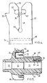
- Figure 1 is an exploded perspective view of a termination and a termination support of one embodiment of an armature according to the invention, the termination being in the form of a commutator segment,
- Figure 2 is a plan view of the termination support of Figure 1, partially sectioned to illustrate the configuration of one of the housings of the termination support,
- Figure 3 is a plan view of one of the terminations of Figure 1 in blank form,
- Figure 4 is an enlarged view of a portion of the termination shown in Figure 2, and
- Figure 5 is a sectional view of the termination support of Figure 1 with a termination mounted thereon and with an armature winding connected thereto.
- Figures 1, 2 and 5 show a unitary plastics moulded
termination support 10. Thesupport 10 has three sections, 12, 14 and 16, and is essentially a hollow cylinder with additional structures provided on its external surface, in itsmiddle section 14. The shaft of an armature (not shown) passes through thesupport 10 and theportion 16 is a spacer which spaces themiddle section 14 of thesupport 10 from the base of the armature stacks (not shown). - The
middle portion 14 of thesupport 10 has fivehousings 18 equally spaced around the circumferance of thesupport 10. -
Section 12 of thesupport 10 provides support for the commutator segments - One of the
housings 18 is best shown in section in figures 2 and 5. Thehousing 18 hasside walls 20, anend wall 22 and acover 24. Theend wall 22 is adjacent thespacer 16 and anopening 26 which faces thecommutator support 12 is provided by thewalls cover 24. Theside walls 20 are parallel with the longitudinal axis of thesupport 10. Eachside wall 20 of thehousing 18 has aslot 30 which extends parallel to the longitudinal axis of thesupport 10, from the commutator end of thehousing 18. - A combined
commutator segment 34 andterminal 36 are illustrated in figure 3 in the form of a blank. Thecommutator segment 34 has abase 38 which carries anoverlay 40. Alug 42 of reduced width is provided at the front end of thebase 38 and thelug 42 has a central struck-uptag 44. Twolugs 42 could be provided, if desired, adjacent opposite edges of thecommutator segment 34. - At its rear end, the base of the
commutator segment 34 is connected to theterminal 36. Theterminal 36 is rectangular with its minor axis coincident with the longitudinal axis of thecommutator segment 34. Theterminal 36 has two key hole shapedslots 48 extending from opposite ends of theterminal 36 along the major axis thereof. Atriangular barb 50 is provided on either side of the minor axis of theterminal 36 along the edge furthest from thecommutator segment 34. - As can be seen from figure 1, the
base 38 and theoverlay 40 of thecommutator segment 34 are of arcuate form which conforms to the external radius of thecommutator support section 12 of thesupport 10. Thelug 42 extends below thebase 38 and back along the length of thecommutator section 34 with thetag 44 projecting below thelug 42.Terminal 36 is bent upright from thecommutator segment 34 and thearms 52 of theterminal 36, which include the respective key hole shapedslots 48, are bent at 90° to thecentral portion 54 of the terminal. Thearms 52 therefore extend parallel to each other and to the longitudinal axis of thecommutator segment 34, and forward along the length thereof. - Figure 4 shows one half of the
terminal 36 of figure 3, on an enlarged scale.Areas 58 are shown in which bending occurs between thecentral portion 54 and thearm 52. However, the main purpose of figure 4 is to illustrate the detailed structure of the key hole shapedslots 48. It is this feature which ensures contact with anarmature winding portion 32, seen in Figure 5. Thetapered mouth 56 provides a funnel for guiding thewinding portion 32 into theslot 48. A short distance into theslot 48 there are located twocutters 62 which havesharp edges 64 projecting into theslot 48. Preferably, thecutters 62 are formed by a precise stamping operation. Alternatively, as shown, thecutters 62 are formed from thearm 52 and partially severed therefrom such that thesharp edges 64 are resiliently urged into theslot 48. Along theslot 48, behind thecutters 62, there is a further small reduction in width.Circular end 66 ofslot 48 ensures that the edges of theslot 48 have a certain resilience to separation by thewinding portion 32. - Figure 5 shows shaped
commutator segment 34 and theterminal 36 in position on thesupport 10. Theterminal 36 is received in and supported by thehousing 18. - The
barb 50 grips thecover 24 of thehousing 18 and therefore retains theterminal 36 within thehousing 18. Further retention is provided if the width of theterminal 36 is a close fit to the internal dimensions of thehousing 18. - The front end of the
support 10 is provided with fivelongitudinal recesses 70 which are cut away at the forward ends so as to meet the curved external surface of thecommutator supporting section 12.Lug 42 ofcommutator segment 34 enters therecess 70 as theterminal 36 enters thehousing 18.Tag 44 oflug 42 is forced into the material of thesupport 10 so as to rigidly restrain thelug 42 withinrecess 70.Commutator segment 34 is rigidly held in position on the supportingsection 12 by interaction ofterminal 36 andhousing 18 at one end and by interaction oflug 42 andtag 44 withrecess 70 at its other end. Thecommutator segment 34 is rigidly held on supportingsection 12 and there is no fear of displacement even during high rotational accelarations. All fivecommutator segments 34 are mounted on thesupport 10 in this way. Thesupport 10 together with thecommutator segments 34 can then be mounted in a jig and thecommutator segments 34 ground down to provide a right cylindrical surface for presentation in use to brush gear. - The
support 10 is then mounted on an armature shaft (not shown) with thespacer 16 pushed against an armature stack. The armature is then placed in a winding jig and the armature coils wound using, for example, enamel coated copper wire. The lead wire of the armature winding is inserted in theslots 48 andslots 30 in one of theterminals 36 and itsrespective housing 18. As the lead wire is drawn intoslots 48, thesharp edges 64 of thecutters 62 sever the insulation on thewire 32 which is deformed as the wire is drawn further into theslots 48, theslots 48 being narrower than the diameter of the wire. Theslots 30 terminate short of the ends ofslots 48 to prevent thewire 32 from entering thecircular ends 66 of theslots 48. Thus intimate metal to metal contact is maintained between thewire 32 and theterminal 36, thearms 52 of theterminal 36 acting as double cantilever springs and exerting a continuous pressure on thewire 32. - From this start, the first armature coil is wound. At the end of the first coil winding the armature is indexed and the
wire 32 is drawn intoslots 48 andslots 30 in thenext terminal 36 andhousing 18 without breaking the continuity of the wire. The winding machine is arranged to do this automatically. - The process is repeated until all coils have been wound and the tail end of the winding is drawn into the
slots 48 andslots 30 of the first terminal and housing until it is adjacent to the lead end. Thewire 32 is then cut and the armature removed from the winding machine. - The material of the
base 38 of thecommutator segment 34 is brass or other metal having similar properties for providing the resilience required for the terminal 36 andlug 42. The overlay is formed of copper which provides the properties necessary for its commutation function. In operation theoverlay 40 will be directly contacted by the brushes of the electric motor. - The invention provides a simple and cheap connection between the armature winding and the commutator. No application of heat is required and the associated risk of distorting the
support 10 is therefore avoided. No embrittlement of the winding wire is caused and problems associated with oxidation are also avoided. The use of flux is negated and there is no chemical reaction or consequent corrosion resulting from the connection. - The
housings 18 are by no means essential, although some support for the terminal 36 is necessary. If thehousings 18 are omitted either the circular ends 66 of theslots 48 must be omitted or some means must be provided to prevent thewire 32 from entering these circular ends 66. - The terminal 36 may be designed with only one
arm 52. Thecommutator segments 34 need not be bimetallic. The commutator segments could be bonded to thecommutator support section 12 and thespacer 16 may include formations co-operating with complementary formations on the winding stacks, so as to prevent angular displacement between thesupport 10 and the armature stacks. The wire of the armature may be formed of a material such as aluminium instead of copper and various sizes of wire can be accommodated. Thesupport 10 could be of metal, e.g. aluminium, provided with an insulating layer of metal oxide. Moreover, instead ofcutters 62 the edges of theslots 48 could be serrated. Also instead of the barrel commutator shown, the commutator may be a face commutator with the commutator segments arranged in a single plane perpendicular to the axis of the armature. - Furthermore, the armature terminations could be in the form of slip rings rather than commutator segments.
Claims (7)
- An armature comprising a winding having a connector portion (32) coated with insulation, an armature termination (34), and a support (10) on which said termination is mounted, said termination (34) having an integral terminal (36) provided with a slot (48) which straddles and grips said connector portion (32), the slot (48) having an open end which faces away from said armature for receiving a connector portion (32) of said winding after the armature termination (34) has been mounted on said support (10) and two cutting edges (64) for cutting through the insulation of the connector portion (32) as it is drawn into the slot (48) to establish electrical contact between the connector portion (32) and the terminal (36), the slot (48) maintaining said electrical contact as it straddles and grips said connector portion (32).
- An armature as claimed in claim 1, wherein said terminal (36) has at least two parallel arms (52) each having a slot (48) which straddles and grips said connector portion (32).
- An armature as claimed in claim 2, wherein said two arms (52) are connected by a transverse portion (54).
- An armature as claimed in any one of the preceding claims, wherein the support (10) includes a housing (18) for said terminal (36).
- An armature as claimed in claim 4, wherein said terminal (36) is provided with a barb (50) for retaining said terminal in said housing (18).
- An armature as claimed in any one of the preceding claims, wherein there are three or more armature terminations in the form of commutator segments (34) fixed to said support (10).
- A method of connecting an armature winding to an armature termination (34), the armature termination (34) being connectable to an external circuit, comprising the steps of providing the termination (34) with an integral terminal (36), the terminal having a slot (48) open at one end facing away from the armature and two cutting edges (64), mounting the termination (34) on a support (10), and subsequently winding the armature, wherein the winding includes a connector portion (32) coated with insultion and wherein said connector portion (32) is drawn into the slot (48) during winding of the armature so that the cutting edges (64) cut through the insulation of the connector portion (32) and the slot (48) straddles and grips the connector portion (32) to maintain electrical contact between the connector portion (32) and the terminal.
Priority Applications (1)
| Application Number | Priority Date | Filing Date | Title |
|---|---|---|---|
| EP87306146A EP0271973B1 (en) | 1986-12-11 | 1987-07-10 | An armature |
Applications Claiming Priority (3)
| Application Number | Priority Date | Filing Date | Title |
|---|---|---|---|
| GB8629624 | 1986-12-11 | ||
| GB8629624A GB2198892B (en) | 1986-12-11 | 1986-12-11 | Armature winding connections. |
| EP87306146A EP0271973B1 (en) | 1986-12-11 | 1987-07-10 | An armature |
Publications (2)
| Publication Number | Publication Date |
|---|---|
| EP0271973A1 EP0271973A1 (en) | 1988-06-22 |
| EP0271973B1 true EP0271973B1 (en) | 1993-04-07 |
Family
ID=26110557
Family Applications (1)
| Application Number | Title | Priority Date | Filing Date |
|---|---|---|---|
| EP87306146A Expired - Lifetime EP0271973B1 (en) | 1986-12-11 | 1987-07-10 | An armature |
Country Status (1)
| Country | Link |
|---|---|
| EP (1) | EP0271973B1 (en) |
Family Cites Families (2)
| Publication number | Priority date | Publication date | Assignee | Title |
|---|---|---|---|---|
| GB2128818B (en) * | 1982-10-11 | 1986-02-12 | Johnson Electric Ind Mfg | An armature |
| JPS59107574U (en) * | 1982-12-29 | 1984-07-19 | マブチモ−タ−株式会社 | Commutator device for small motors |
-
1987
- 1987-07-10 EP EP87306146A patent/EP0271973B1/en not_active Expired - Lifetime
Also Published As
| Publication number | Publication date |
|---|---|
| EP0271973A1 (en) | 1988-06-22 |
Similar Documents
| Publication | Publication Date | Title |
|---|---|---|
| US4584498A (en) | Commutator with winding connections | |
| US4769627A (en) | Armature coil commutator connector | |
| EP0282670B1 (en) | An armature for an electric motor | |
| EP0571072B1 (en) | An assembled commutator | |
| EP0271175B1 (en) | A commutator | |
| EP0350193B1 (en) | An armature | |
| US4983871A (en) | Commutator with base alignment interlock | |
| GB2223888A (en) | Assembled commutator for electric motor | |
| GB2199195A (en) | A disc-type armature having insulating cutting correctors | |
| EP0271973B1 (en) | An armature | |
| EP0282671A1 (en) | A method of connecting an armature winding to a commutator segment | |
| EP0349142A1 (en) | An armature | |
| GB2202384A (en) | Connecting armature winding to commutator segments of an electric motor | |
| GB2204453A (en) | Connections between armature windings and commutator segments for an electric motor | |
| KR970006107B1 (en) | An armature for an electrical device and a method of connecting an armature winding to an armature termination | |
| KR970006108B1 (en) | Armature | |
| GB2203596A (en) | Winding connections retention in an armature for an electric motor |
Legal Events
| Date | Code | Title | Description |
|---|---|---|---|
| PUAI | Public reference made under article 153(3) epc to a published international application that has entered the european phase |
Free format text: ORIGINAL CODE: 0009012 |
|
| AK | Designated contracting states |
Kind code of ref document: A1 Designated state(s): DE FR GB IT |
|
| EL | Fr: translation of claims filed | ||
| DET | De: translation of patent claims | ||
| 17P | Request for examination filed |
Effective date: 19881028 |
|
| RAP1 | Party data changed (applicant data changed or rights of an application transferred) |
Owner name: JOHNSON ELECTRIC S.A. |
|
| 17Q | First examination report despatched |
Effective date: 19910709 |
|
| GRAA | (expected) grant |
Free format text: ORIGINAL CODE: 0009210 |
|
| AK | Designated contracting states |
Kind code of ref document: B1 Designated state(s): DE FR GB IT |
|
| ITF | It: translation for a ep patent filed |
Owner name: BUGNION S.P.A. |
|
| REF | Corresponds to: |
Ref document number: 3785314 Country of ref document: DE Date of ref document: 19930513 |
|
| ET | Fr: translation filed | ||
| PLBE | No opposition filed within time limit |
Free format text: ORIGINAL CODE: 0009261 |
|
| STAA | Information on the status of an ep patent application or granted ep patent |
Free format text: STATUS: NO OPPOSITION FILED WITHIN TIME LIMIT |
|
| 26N | No opposition filed | ||
| REG | Reference to a national code |
Ref country code: GB Ref legal event code: IF02 |
|
| PGFP | Annual fee paid to national office [announced via postgrant information from national office to epo] |
Ref country code: GB Payment date: 20060705 Year of fee payment: 20 |
|
| PGFP | Annual fee paid to national office [announced via postgrant information from national office to epo] |
Ref country code: DE Payment date: 20060706 Year of fee payment: 20 |
|
| PGFP | Annual fee paid to national office [announced via postgrant information from national office to epo] |
Ref country code: FR Payment date: 20060719 Year of fee payment: 20 |
|
| PGFP | Annual fee paid to national office [announced via postgrant information from national office to epo] |
Ref country code: IT Payment date: 20060731 Year of fee payment: 20 |
|
| REG | Reference to a national code |
Ref country code: GB Ref legal event code: PE20 |
|
| PG25 | Lapsed in a contracting state [announced via postgrant information from national office to epo] |
Ref country code: GB Free format text: LAPSE BECAUSE OF EXPIRATION OF PROTECTION Effective date: 20070709 |