EP0271859B1 - Compact coiled coil incandescent filament using pitch for sag control - Google Patents
Compact coiled coil incandescent filament using pitch for sag control Download PDFInfo
- Publication number
- EP0271859B1 EP0271859B1 EP87118491A EP87118491A EP0271859B1 EP 0271859 B1 EP0271859 B1 EP 0271859B1 EP 87118491 A EP87118491 A EP 87118491A EP 87118491 A EP87118491 A EP 87118491A EP 0271859 B1 EP0271859 B1 EP 0271859B1
- Authority
- EP
- European Patent Office
- Prior art keywords
- filament
- lamp
- diameter
- pitch
- coil
- Prior art date
- Legal status (The legal status is an assumption and is not a legal conclusion. Google has not performed a legal analysis and makes no representation as to the accuracy of the status listed.)
- Expired - Lifetime
Links
- 238000004804 winding Methods 0.000 claims description 21
- 229910052736 halogen Inorganic materials 0.000 claims description 16
- 238000000034 method Methods 0.000 claims description 10
- 229910052721 tungsten Inorganic materials 0.000 claims description 10
- 239000010937 tungsten Substances 0.000 claims description 10
- 150000002367 halogens Chemical class 0.000 claims description 9
- -1 tungsten halogen Chemical class 0.000 claims description 7
- 150000004820 halides Chemical class 0.000 claims description 4
- 239000003870 refractory metal Substances 0.000 claims description 4
- WFKWXMTUELFFGS-UHFFFAOYSA-N tungsten Chemical compound [W] WFKWXMTUELFFGS-UHFFFAOYSA-N 0.000 claims description 4
- 238000004519 manufacturing process Methods 0.000 claims description 3
- 239000011248 coating agent Substances 0.000 claims 1
- 238000000576 coating method Methods 0.000 claims 1
- 239000002775 capsule Substances 0.000 description 14
- 239000011521 glass Substances 0.000 description 5
- 239000007789 gas Substances 0.000 description 4
- 239000000463 material Substances 0.000 description 4
- XKRFYHLGVUSROY-UHFFFAOYSA-N Argon Chemical compound [Ar] XKRFYHLGVUSROY-UHFFFAOYSA-N 0.000 description 2
- IJGRMHOSHXDMSA-UHFFFAOYSA-N Atomic nitrogen Chemical compound N#N IJGRMHOSHXDMSA-UHFFFAOYSA-N 0.000 description 2
- 230000003247 decreasing effect Effects 0.000 description 2
- 239000011261 inert gas Substances 0.000 description 2
- 230000003287 optical effect Effects 0.000 description 2
- 239000010453 quartz Substances 0.000 description 2
- VYPSYNLAJGMNEJ-UHFFFAOYSA-N silicon dioxide Inorganic materials O=[Si]=O VYPSYNLAJGMNEJ-UHFFFAOYSA-N 0.000 description 2
- ZOKXTWBITQBERF-UHFFFAOYSA-N Molybdenum Chemical compound [Mo] ZOKXTWBITQBERF-UHFFFAOYSA-N 0.000 description 1
- 239000005354 aluminosilicate glass Substances 0.000 description 1
- 238000013459 approach Methods 0.000 description 1
- 229910052786 argon Inorganic materials 0.000 description 1
- 230000015572 biosynthetic process Effects 0.000 description 1
- 238000005034 decoration Methods 0.000 description 1
- 230000001627 detrimental effect Effects 0.000 description 1
- 239000006185 dispersion Substances 0.000 description 1
- 238000009826 distribution Methods 0.000 description 1
- 230000008030 elimination Effects 0.000 description 1
- 238000003379 elimination reaction Methods 0.000 description 1
- 238000009730 filament winding Methods 0.000 description 1
- 238000007689 inspection Methods 0.000 description 1
- 230000003993 interaction Effects 0.000 description 1
- 230000002452 interceptive effect Effects 0.000 description 1
- 229910052743 krypton Inorganic materials 0.000 description 1
- DNNSSWSSYDEUBZ-UHFFFAOYSA-N krypton atom Chemical compound [Kr] DNNSSWSSYDEUBZ-UHFFFAOYSA-N 0.000 description 1
- 229910052750 molybdenum Inorganic materials 0.000 description 1
- 239000011733 molybdenum Substances 0.000 description 1
- 229910052757 nitrogen Inorganic materials 0.000 description 1
- 230000008569 process Effects 0.000 description 1
- 230000009467 reduction Effects 0.000 description 1
- 230000007480 spreading Effects 0.000 description 1
- 238000003892 spreading Methods 0.000 description 1
- 229910052724 xenon Inorganic materials 0.000 description 1
- FHNFHKCVQCLJFQ-UHFFFAOYSA-N xenon atom Chemical compound [Xe] FHNFHKCVQCLJFQ-UHFFFAOYSA-N 0.000 description 1
Images

Classifications
-
- H—ELECTRICITY
- H01—ELECTRIC ELEMENTS
- H01K—ELECTRIC INCANDESCENT LAMPS
- H01K1/00—Details
- H01K1/18—Mountings or supports for the incandescent body
-
- H—ELECTRICITY
- H01—ELECTRIC ELEMENTS
- H01K—ELECTRIC INCANDESCENT LAMPS
- H01K1/00—Details
- H01K1/02—Incandescent bodies
- H01K1/14—Incandescent bodies characterised by the shape
Definitions
- the present invention is directed to a unique coiled coil incandescent filament and supports therefor, especially useful in a European version of Sylvania's Capsylite lamps.
- Both PAR and A-line versions of these lamps are commercially available in the United States.
- the U.S. versions of these lamps are characterized by a low-wattage, tungsten - halogen, hard glass light-source capsule, mounted within a heavy outer envelope. See, for example, U.S. Patent No. 4,598,225.
- EP-A-0 241 911 (falling within the terms of Article 54(3) EPC) and GB-A-1 147 140 disclose filaments of the first part of present Claim 1.
- parabolic aluminized reflector (PAR), elliptical reflector (ER), or reflector (R) lamps for general spot, downlighting, and/or flood lighting applications is well established.
- PAR, ER type lamps have been accepted as the lamps of choice for short to medium distance outdoor uses, as well as for indoor display, decoration, accent, and inspection applications of down lighting.
- incandescent PAR-type lamps particularly Sylvania's PAR38, have used a filament mounted transversely in the reflector, that is, perpendicular to its axis of symmetry, because this was the simplest configuration to manufacture.
- Capsylite lamps operating under United States type electrical systems i.e., 120-130V; 60 Hertz
- such compact filaments are made possible by the use of a halfwave rectifying diode which effectively reduces the capsule voltage from 120V to about 84V.
- the lamp need not be hermetic and bonded beam lamps have appeared.
- Coiled filaments are known, see for example, U.S. Patent Nos. 1,180,159; 1,247,068; 2,142,865; 2,306,925; 2,774,918; 4,208,609; and 4,316,116. However, none of these coiled filaments provides the unique features of the filament of the present invention.
- Filament supports typically cause shadowing and scattering of light. Examples of typical filament supports may be found in U.S. Patent Nos. 4,359,665; 4,208,606; 3,780,333; 3,736,455; 3,678,319; 3,634,722; 3,335,312; and 3,173,051.
- quartz halogen capsules in the 220-250V range have been made, they are generally inefficient and complicated affairs with zig-zagged" filaments and multiple coil supports.
- quartz capsules are not well suited for use in PAR lamps since they are lacking both in luminous efficiency and in optical efficiency. They are also more expensive to produce than hard glass capsules due to the high cost of materials and processes involved and the amount of labor required.
- the present invention overcomes the difficulties mentioned above with respect to European type PAR and A-line lamps by providing a unique filament and non-interfering supports therefor.
- the present invention is directed to a low wattage ( ⁇ 150W) high voltage (120-250V) halogen coil filament particularly well suited for use in European type PAR and A-line lamps.
- the present invention provides a method of making a coiled coil incandescent filament, said method comprising the steps of:
- Such filaments may be used in incandescent lamps, in particular ones with a halogen or halide gas fill.
- an improved halogen coil lamp including a compact high efficiency filament mounted axially in a single ended hard glass capsule with a unique system of supports sufficient to prevent significant coil sag over the useful life thereof.
- the parameters of the filament of the present invention are new.
- a filament prepared in accordance with these parameters demonstrates improved compactness and structural rigidity which, together with the unique supplementary supports therefor, provides a suitable light-source for lamps operating under European electrical systems (220-250 volts and 50 Hertz).
- Figure 1 illustrates one embodiment of an incandescent lamp, particularly of the tungsten halogen variety, made in accordance with the teachings of the present invention.
- Figure 2 illustrates a filament wire which was wound to form a coiled filament.
- Figure 3 illustrates a filament wire which was wound to form a coiled coil filament.
- Figure 4 illustrates a filament wire wound around a primary mandrel to form a primary coil.
- Figure 5 illustrates a primary coil which is wound around a secondary mandrel to form the coiled coil filament.
- Figure 6 illustrates the various parameters related to determining the outer diameter of a coiled coil filament of the present invention.
- This invention relates to a multiple coiled filament and system of supports.
- the filament consists of a single strand wire, coreless, coiled coil filament for an incandescent lamp.
- the supports allow a simple, inexpensive and efficient coil to be constructed.
- Figure 1 represents an example of an incandescent lamp 10, in this embodiment being of the tungsten halogen variety, prepared in accordance with the teachings of this invention.
- lamp 10 comprises a tubular envelope 12, prepared from a suitable light transmissive material, such as aluminosilicate glass.
- a pair of lead in wires 14 and 16, portions of which serve as mounting means, are press sealed in envelope 12 at press seal 18.
- Lead in wires 14 and 16 can be formed from any suitable material, for example, molybdenum, which will form a relatively strain free hermetic seal with glass envelope 12.
- a refractory metal such as tungsten, is used to form the coiled coil filament 20 in accordance with the teachings of this invention.
- Coiled coil filament 20 is provided with legs 21 at each end thereof during its formation.
- envelope 12 is filled with a fill gas, comprising an inert gas and a suitable halogen or halide.
- a fill gas comprising an inert gas and a suitable halogen or halide.
- fill gases include the inert gases; argon, krypton, xenon, and/or nitrogen; plus the halogen or halide.
- FIGS 2 and 3 illustrate enlarged views of the preferred tungsten filament of the present invention and its coiled and coiled coiled stages, respectively.
- Each stage has a pitch or percent pitch, which is equal to S, the center to center spacing of the turns, divided by d, the diameter of the wire or coil, multiplied by 100.
- Figure 2 illustrates the primary pitch of a filament 20A having a center to center spacing of S 1 , wire diameter d 1 , and outer diameter D 1 .
- the primary pitch P 1 is equal to S 1 /d 1 and the secondary pitch P 2 is equal to S 2 /d 2 .
- d 2 D 1 .
- P 1 has a value that does not exceed 1.70 (or 170%).
- S 2 is the center to center spacing of the coiled coil filament
- BL is the body length of the coiled coil (or secondary) filament.
- the secondary pitch of the filament is in the range of from 1.40 to 1.60.
- the present method comprises the steps of (1) providing a strand of fibrous filament wire 19 having a particular length L and a diameter d (for a particular wattage, voltage and efficiency) and (2) winding filament wire 19 around a primary mandrel 30 having a diameter of M 1 to produce a primary coil 20A.
- the method of the present invention further includes the step (3) of winding the primary coil 20A around a secondary mandrel 40 having a secondary mandrel diameter of M 2 to produce a coiled coil filament configuration, where B ⁇ A.
- the method of the present invention further includes the step (4) of removing substantially all of the core of the coiled coil filament 20 except for the core in legs 21.
- the core in legs 21 is preferably left intact in order to preserve the structural integrity of filament 20 when it is mounted within the envelope and crimped or attached by the legs to a mounting means.
- Figure 6 illustrates the outer diameter D 2 of the filament winding illustrated in Figure 5, wherein the primary mandrel diameter M 1 is greater than the diameter of filament wire 19 and the secondary mandrel diameter M 2 is greater than the diameter of the primary filament coil 20A.
- the most preferred coil configuration is centered in the bulb (CC8 configuration) to equalize bulb wall temperature. At the higher wattages, this allows bulb wall loading to be minimized. At the lower wattages, this allows the minimum bulb wall temperature (required for operation of the tungsten halogen cycle) to be achieved without cold spots.
- Centering the coil in the bulb is also important for filaments focussed in reflectors since this equalizes the light distribution about the central axis of the reflector.
- the resulting body length is about 14 mm.
- Improved windings # 1, 2, and 3 represent length reductions of about 39%, 57% and 67% respectively, compared to the sample filament.
- filaments designed to operate at line voltage such as 120 or 130 volts also require starting with a long filament wire.
- the improved method for reducing focus loss and improving collection efficiency will provide for winding a filament wire into a compact coil which is especially useful for these applications and can lead to enhanced operation at high voltages since typical winding techniques has led to extremely long filaments requiring larger envelopes, more complex mounting arrangements and a greater dispersion of light.
- the aforementioned filament design can also lead to operation without voltage reducing or rectifying means (e.g., a diode) which eliminates the modulation of the light and power fluctuations that result from the use of such rectifying means. Elimination of the rectifying means is particularly important in the 225 to 245 volt range since the small filament mass leads to greater thermal fluctuations and useful where small reflector lamp designs are sought due to the heat generated by the lamp capsule that the rectifier is exposed to.
- voltage reducing or rectifying means e.g., a diode
Landscapes
- Resistance Heating (AREA)
Description
- The present invention is directed to a unique coiled coil incandescent filament and supports therefor, especially useful in a European version of Sylvania's Capsylite lamps. Both PAR and A-line versions of these lamps are commercially available in the United States. The U.S. versions of these lamps are characterized by a low-wattage, tungsten - halogen, hard glass light-source capsule, mounted within a heavy outer envelope. See, for example, U.S. Patent No. 4,598,225. EP-A-0 241 911 (falling within the terms of Article 54(3) EPC) and GB-A-1 147 140 disclose filaments of the first part of present Claim 1.
- The use of parabolic aluminized reflector (PAR), elliptical reflector (ER), or reflector (R) lamps for general spot, downlighting, and/or flood lighting applications is well established. In particular, R, PAR, and ER type lamps have been accepted as the lamps of choice for short to medium distance outdoor uses, as well as for indoor display, decoration, accent, and inspection applications of down lighting.
- Traditionally, incandescent PAR-type lamps, particularly Sylvania's PAR38, have used a filament mounted transversely in the reflector, that is, perpendicular to its axis of symmetry, because this was the simplest configuration to manufacture.
- The result of this configuration is an asymmetric beam pattern and the spreading of stray light outside of the useful beam. Additionally, the necessity of maintaining the proper atmosphere in the outer jacket required that the lamp be hermetically sealed with the lens flame-sealed to the reflector.
- With the introduction of Sylvania's Capsylite PAR lamps, which use a halogen capsule as a light source, came lamps with axially mounted filaments which yield a more symmetric beam pattern and more efficient collection of light by the reflector into a useful beam.
- Part of this gain in optical efficiency is due to the fact that the Capsylite lamps use a compact filament which more nearly approaches the theoretically ideal "point" source.
- In Capsylite lamps operating under United States type electrical systems (i.e., 120-130V; 60 Hertz) such compact filaments are made possible by the use of a halfwave rectifying diode which effectively reduces the capsule voltage from 120V to about 84V. Furthermore, since the atmosphere in the outer envelope is no longer critical because of the capsule, the lamp need not be hermetic and bonded beam lamps have appeared.
- In European line voltage PAR lamps, typically of 220 to 250V, halogen capsules have not been used because of the exceedingly fine wire that is required at this high voltage.
- Low wattage (<150W), line voltage filaments tend to be long and flimsy, prone to sag and requiring multiple supports which reduce efficiency. Voltage reducing diodes cannot be used because they produce objectionable flickering of the filament when run on the 50 cycle AC which is standard in Europe.
- "Folded" filaments tend to have detrimental interactions between adjacent sections of the filament which will reduce life.
- Coiled filaments are known, see for example, U.S. Patent Nos. 1,180,159; 1,247,068; 2,142,865; 2,306,925; 2,774,918; 4,208,609; and 4,316,116. However, none of these coiled filaments provides the unique features of the filament of the present invention.
- Filament supports typically cause shadowing and scattering of light. Examples of typical filament supports may be found in U.S. Patent Nos. 4,359,665; 4,208,606; 3,780,333; 3,736,455; 3,678,319; 3,634,722; 3,335,312; and 3,173,051.
- While quartz halogen capsules in the 220-250V range have been made, they are generally inefficient and complicated affairs with zig-zagged" filaments and multiple coil supports.
- Thus, conventional quartz capsules are not well suited for use in PAR lamps since they are lacking both in luminous efficiency and in optical efficiency. They are also more expensive to produce than hard glass capsules due to the high cost of materials and processes involved and the amount of labor required.
- The present invention overcomes the difficulties mentioned above with respect to European type PAR and A-line lamps by providing a unique filament and non-interfering supports therefor.
- The present invention is directed to a low wattage (<150W) high voltage (120-250V) halogen coil filament particularly well suited for use in European type PAR and A-line lamps.
- Viewed from one aspect the present invention provides an incandescent filament comprising a coiled coil of refractory metal wire having a diameter d, wherein the primary winding diameter D1 and the secondary winding diameter D2 of said filament are defined by the equations:


- Viewed from another aspect the present invention provides a method of making a coiled coil incandescent filament, said method comprising the steps of:
- winding a filament wire having a diameter d, around a primary mandrel having a diameter M1 to produce a primary coil having a primary winding diameter D1 and winding said primary coil around a secondary mandrel having a diameter M2, to produce a coiled coil filament having a secondary winding diameter D2 which satisfy the equations:


- Such filaments may be used in incandescent lamps, in particular ones with a halogen or halide gas fill.
- Thus in at least preferred embodiments there is provided an improved halogen coil lamp, the improvements including a compact high efficiency filament mounted axially in a single ended hard glass capsule with a unique system of supports sufficient to prevent significant coil sag over the useful life thereof.
- The parameters of the filament of the present invention are new. A filament prepared in accordance with these parameters demonstrates improved compactness and structural rigidity which, together with the unique supplementary supports therefor, provides a suitable light-source for lamps operating under European electrical systems (220-250 volts and 50 Hertz).
- Figure 1 illustrates one embodiment of an incandescent lamp, particularly of the tungsten halogen variety, made in accordance with the teachings of the present invention.
- Figure 2 illustrates a filament wire which was wound to form a coiled filament.
- Figure 3 illustrates a filament wire which was wound to form a coiled coil filament.
- Figure 4 illustrates a filament wire wound around a primary mandrel to form a primary coil.
- Figure 5 illustrates a primary coil which is wound around a secondary mandrel to form the coiled coil filament.
- Figure 6 illustrates the various parameters related to determining the outer diameter of a coiled coil filament of the present invention.
- This invention relates to a multiple coiled filament and system of supports. The filament consists of a single strand wire, coreless, coiled coil filament for an incandescent lamp. The supports allow a simple, inexpensive and efficient coil to be constructed.
- Figure 1 represents an example of an
incandescent lamp 10, in this embodiment being of the tungsten halogen variety, prepared in accordance with the teachings of this invention. - As illustrated,
lamp 10 comprises atubular envelope 12, prepared from a suitable light transmissive material, such as aluminosilicate glass. A pair of lead inwires 14 and 16, portions of which serve as mounting means, are press sealed inenvelope 12 atpress seal 18. - Lead in
wires 14 and 16 can be formed from any suitable material, for example, molybdenum, which will form a relatively strain free hermetic seal withglass envelope 12. A refractory metal, such as tungsten, is used to form thecoiled coil filament 20 in accordance with the teachings of this invention. Coiledcoil filament 20 is provided withlegs 21 at each end thereof during its formation. - In this embodiment,
envelope 12 is filled with a fill gas, comprising an inert gas and a suitable halogen or halide. Preferred examples of fill gases useful herein include the inert gases; argon, krypton, xenon, and/or nitrogen; plus the halogen or halide. - Figures 2 and 3 illustrate enlarged views of the preferred tungsten filament of the present invention and its coiled and coiled coiled stages, respectively. Each stage has a pitch or percent pitch, which is equal to S, the center to center spacing of the turns, divided by d, the diameter of the wire or coil, multiplied by 100.
- Specifically, Figure 2 illustrates the primary pitch of a
filament 20A having a center to center spacing of S1, wire diameter d1, and outer diameter D1. In the present invention, the primary pitch P1 is equal to S1/d1 and the secondary pitch P2 is equal to S2/d2. Note: d2 = D1.P1 has a value that does not exceed 1.70 (or 170%). - In Figure 3, S2 is the center to center spacing of the coiled coil filament, d2 (d2 = D1) is the primary coil diameter, and BL is the body length of the coiled coil (or secondary) filament. The secondary pitch of the filament is in the range of from 1.40 to 1.60.
- The method of forming the coiled coil filament of the present invention is represented by Figures 4-6.
- With reference to Figure 4, the present method comprises the steps of (1) providing a strand of
fibrous filament wire 19 having a particular length L and a diameter d (for a particular wattage, voltage and efficiency) and (2) windingfilament wire 19 around aprimary mandrel 30 having a diameter of M1 to produce aprimary coil 20A. - With reference to Figure 5, the method of the present invention further includes the step (3) of winding the
primary coil 20A around a secondary mandrel 40 having a secondary mandrel diameter of M2 to produce a coiled coil filament configuration, where B ≥ A. - As illustrated in Figures 4 and 5, respectively, the primary winding diameter D1 and the secondary winding diameter D2 of the filament are:

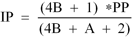
such that the filament exhibits an increase in compactness and retains or exhibits an increase in structural rigidity. - Surprisingly it has been discovered that B can range from about 3.0 to about 10.0 (when A satisfies the equation 1.40 ≤ A ≤ 3.0) and when the primary pitch is decreased so that the inner pitch (IP) satisfies the condition 1.08 ≤ IP ≤ 1.35, and where:

- The method of the present invention further includes the step (4) of removing substantially all of the core of the coiled
coil filament 20 except for the core inlegs 21. The core inlegs 21 is preferably left intact in order to preserve the structural integrity offilament 20 when it is mounted within the envelope and crimped or attached by the legs to a mounting means. - Figure 6 illustrates the outer diameter D2 of the filament winding illustrated in Figure 5, wherein the primary mandrel diameter M1 is greater than the diameter of
filament wire 19 and the secondary mandrel diameter M2 is greater than the diameter of theprimary filament coil 20A. - The most preferred coil configuration is centered in the bulb (CC8 configuration) to equalize bulb wall temperature. At the higher wattages, this allows bulb wall loading to be minimized. At the lower wattages, this allows the minimum bulb wall temperature (required for operation of the tungsten halogen cycle) to be achieved without cold spots.
- Centering the coil in the bulb is also important for filaments focussed in reflectors since this equalizes the light distribution about the central axis of the reflector.
- An example of a filament improved by the present invention follows:

- In the sample winding, where the mandrel ratios are low, the resulting body length is about 14 mm. Improved windings # 1, 2, and 3 represent length reductions of about 39%, 57% and 67% respectively, compared to the sample filament.
- With respect to lamps designing reflector type lamps for operating at high voltages, especially for overseas operation at 225 and 245 volts, such lamps typically require starting off with extremely long filament wires.
- In addition, filaments designed to operate at line voltage such as 120 or 130 volts also require starting with a long filament wire. The improved method for reducing focus loss and improving collection efficiency will provide for winding a filament wire into a compact coil which is especially useful for these applications and can lead to enhanced operation at high voltages since typical winding techniques has led to extremely long filaments requiring larger envelopes, more complex mounting arrangements and a greater dispersion of light.
- Furthermore, the aforementioned filament design can also lead to operation without voltage reducing or rectifying means (e.g., a diode) which eliminates the modulation of the light and power fluctuations that result from the use of such rectifying means. Elimination of the rectifying means is particularly important in the 225 to 245 volt range since the small filament mass leads to greater thermal fluctuations and useful where small reflector lamp designs are sought due to the heat generated by the lamp capsule that the rectifier is exposed to.
- The more compact coil that results herein also leads to a smaller capsule size which provides the following heretofore unavailable advantages:
- 1. Allows for the operation of lower wattage tungsten halogen capsules at higher voltages since the bulb wall loading is increased;
- 2. Allows for the use of high pressure tungsten halogen capsules, which in turn leads to lower capsule energy and thus improved containment during lamp arc-out during lamp failure; and
- 3. Allows for lower overall material costs for lamp parts such as glass, fill gas, and outer jacket.
Claims (12)
- An incandescent filament comprising a coiled coil (20) of refractory metal wire (19) having a diameter d, wherein the primary winding diameter D1 and the secondary winding diameter D2 of said filament (20) are defined by the equations:


characterised in that the inner pitch, IP, of said coiled coil filament (20) satisfies the condition:
- A filament as claimed in claim 1, wherein the primary pitch, PP, ranges from 1.55 to 1.25.
- A filament as claimed in claim 1 or 2, wherein the refractory metal wire (19) comprises tungsten.
- An incandescent lamp having a filament as claimed in any preceding claim.
- A lamp as claimed in claim 4, wherein said lamp is a tungsten halogen lamp having a halogen or a halide as a part of a fill gas.
- A lamp as claimed in claim 4 or 5, wherein the filament coil configuration (20) is centered in the bulb.
- A lamp as claimed in any of claims 4 to 6, wherein said lamp includes a pair of lead-in wires (14,16), press sealed in said envelope (12) and extending therefrom.
- A lamp as claimed in any of claims 4 to 7, which further comprises a reflector.
- A lamp as claimed in any of claims 7 or 8, wherein said lamp further includes rectifying or other voltage reducing means electrically coupled to one of said lead-in wires (14,16), in series with said filament (20), and coupled to a voltage source thereby reducing the voltage across said filament (20).
- A lamp as claimed in any of claims 4 to 9, wherein said envelope (12) includes an infrared reflective coating such that infrared light is reflected back to said filament (20).
- A method of making a coiled coil incandescent filament, said method comprising the steps of:winding a filament wire (19) having a diameter d, around a primary mandrel (30) having a diameter M1 to produce a primary coil (20A) having a primary winding diameter D1 and winding said primary coil (20A) around a secondary mandrel having a diameter M2, to produce a coiled coil filament (20) having a secondary winding diameter D2 which satisfy the equations:


- A method as claimed in claim 11, further comprising the step of removing substantially all of the core of said coiled coil filament (20), except at the legs (21) thereof.
Applications Claiming Priority (2)
| Application Number | Priority Date | Filing Date | Title |
|---|---|---|---|
| US94233286A | 1986-12-16 | 1986-12-16 | |
| US942332 | 2001-08-28 |
Publications (3)
| Publication Number | Publication Date |
|---|---|
| EP0271859A2 EP0271859A2 (en) | 1988-06-22 |
| EP0271859A3 EP0271859A3 (en) | 1990-05-09 |
| EP0271859B1 true EP0271859B1 (en) | 1997-04-02 |
Family
ID=25477937
Family Applications (1)
| Application Number | Title | Priority Date | Filing Date |
|---|---|---|---|
| EP87118491A Expired - Lifetime EP0271859B1 (en) | 1986-12-16 | 1987-12-14 | Compact coiled coil incandescent filament using pitch for sag control |
Country Status (2)
| Country | Link |
|---|---|
| EP (1) | EP0271859B1 (en) |
| DE (1) | DE3752040T2 (en) |
Cited By (1)
| Publication number | Priority date | Publication date | Assignee | Title |
|---|---|---|---|---|
| US7932665B2 (en) | 2008-12-02 | 2011-04-26 | Osram Sylvania Inc. | Dual filament lamp for rapid temperature processing |
Citations (2)
| Publication number | Priority date | Publication date | Assignee | Title |
|---|---|---|---|---|
| GB1147140A (en) * | 1967-03-10 | 1969-04-02 | Sylvania Electric Prod | Incandescent lamp |
| EP0241911A2 (en) * | 1986-04-14 | 1987-10-21 | GTE Products Corporation | An improved reflector-type lamp having reduced focus loss |
Family Cites Families (8)
| Publication number | Priority date | Publication date | Assignee | Title |
|---|---|---|---|---|
| GB441207A (en) * | 1934-07-18 | 1936-01-15 | Gen Electric Co Ltd | Improvements in the manufacture of coiled coil filaments for electric incandescent lamps |
| US2359302A (en) * | 1942-06-11 | 1944-10-03 | Tung Sol Lamp Works Inc | Incandescent lamp and method of manufacture |
| US3383539A (en) * | 1967-02-06 | 1968-05-14 | Sylvania Electric Prod | Projection lamp |
| US4012659A (en) * | 1975-12-31 | 1977-03-15 | Gte Sylvania Incorporated | Method of flashing tungsten filament |
| US4316116A (en) * | 1979-12-19 | 1982-02-16 | General Electric Company | Triple-coil incandescent filament |
| US4598225A (en) * | 1983-02-25 | 1986-07-01 | Gte Products Corporation | Electric lamp with high outer-envelope to inner-envelope wall-thickness ratio |
| US4499401A (en) * | 1983-03-03 | 1985-02-12 | General Electric Company | Triple coil incandescent filament |
| US4547704A (en) * | 1983-08-01 | 1985-10-15 | General Electric Company | Higher efficiency incandescent lighting units |
-
1987
- 1987-12-14 DE DE19873752040 patent/DE3752040T2/en not_active Expired - Fee Related
- 1987-12-14 EP EP87118491A patent/EP0271859B1/en not_active Expired - Lifetime
Patent Citations (2)
| Publication number | Priority date | Publication date | Assignee | Title |
|---|---|---|---|---|
| GB1147140A (en) * | 1967-03-10 | 1969-04-02 | Sylvania Electric Prod | Incandescent lamp |
| EP0241911A2 (en) * | 1986-04-14 | 1987-10-21 | GTE Products Corporation | An improved reflector-type lamp having reduced focus loss |
Cited By (1)
| Publication number | Priority date | Publication date | Assignee | Title |
|---|---|---|---|---|
| US7932665B2 (en) | 2008-12-02 | 2011-04-26 | Osram Sylvania Inc. | Dual filament lamp for rapid temperature processing |
Also Published As
| Publication number | Publication date |
|---|---|
| EP0271859A2 (en) | 1988-06-22 |
| DE3752040D1 (en) | 1997-05-07 |
| EP0271859A3 (en) | 1990-05-09 |
| DE3752040T2 (en) | 1997-10-30 |
Similar Documents
| Publication | Publication Date | Title |
|---|---|---|
| EP0241911B1 (en) | An improved reflector-type lamp having reduced focus loss | |
| US4298822A (en) | Folded fluorescent lamp and socket | |
| US4480212A (en) | Extended life incandescent lamp with self contained diode and reflector | |
| CA2015563C (en) | Filament alignment spud for incandescent lamps | |
| US4918354A (en) | Compact coiled coil incandescent filament with supports and pitch control | |
| US4683397A (en) | Compact incandescent coiled coil filament | |
| EP0364831B1 (en) | Electric incandescent lamp and method of manufacture therefor | |
| CA2178307A1 (en) | Halogen incandescent lamp with filament positioning arrangement | |
| EP0271857B1 (en) | Compact coiled coil incandescent filament with supports | |
| EP0429256B1 (en) | Improved mount structure for double ended lamp | |
| US6639364B1 (en) | Halogen incandescent capsule having filament leg clamped in press seal | |
| US7468576B2 (en) | Multi-segment filament high output halogen lamp | |
| US6225731B1 (en) | Glass halogen lamp with internal ellipsoidal shroud | |
| US4835443A (en) | High voltage hard glass halogen capsule | |
| EP0271859A2 (en) | Compact coiled coil incandescent filament using pitch for sag control | |
| EP0271858B1 (en) | High voltage hard glass halogen capsule | |
| EP0465198A2 (en) | Reflector lamp | |
| JPS63174263A (en) | Incandescent lamp with improved coil construction | |
| WO2005059950A2 (en) | Electric incandescent lamp and method for fabrication thereof | |
| EP0801417A2 (en) | Double-ended type halogen lamp and method of making the same | |
| JPH08124523A (en) | Fluorescent lamp, discharge lamp lighting device and lighting device | |
| CA1218691A (en) | Incandescent lamp source utilizing an integral cylindrical transparent heat mirror | |
| CA1280151C (en) | Compact incandescent coiled coil filament | |
| JP3523377B2 (en) | End-filled incandescent lamp and method of manufacturing the same |
Legal Events
| Date | Code | Title | Description |
|---|---|---|---|
| PUAI | Public reference made under article 153(3) epc to a published international application that has entered the european phase |
Free format text: ORIGINAL CODE: 0009012 |
|
| 17P | Request for examination filed |
Effective date: 19880112 |
|
| AK | Designated contracting states |
Kind code of ref document: A2 Designated state(s): BE DE FR GB NL |
|
| PUAL | Search report despatched |
Free format text: ORIGINAL CODE: 0009013 |
|
| AK | Designated contracting states |
Kind code of ref document: A3 Designated state(s): BE DE FR GB NL |
|
| 17Q | First examination report despatched |
Effective date: 19921223 |
|
| GRAG | Despatch of communication of intention to grant |
Free format text: ORIGINAL CODE: EPIDOS AGRA |
|
| GRAH | Despatch of communication of intention to grant a patent |
Free format text: ORIGINAL CODE: EPIDOS IGRA |
|
| GRAH | Despatch of communication of intention to grant a patent |
Free format text: ORIGINAL CODE: EPIDOS IGRA |
|
| GRAA | (expected) grant |
Free format text: ORIGINAL CODE: 0009210 |
|
| AK | Designated contracting states |
Kind code of ref document: B1 Designated state(s): BE DE FR GB NL |
|
| REF | Corresponds to: |
Ref document number: 3752040 Country of ref document: DE Date of ref document: 19970507 |
|
| ET | Fr: translation filed | ||
| PLBE | No opposition filed within time limit |
Free format text: ORIGINAL CODE: 0009261 |
|
| STAA | Information on the status of an ep patent application or granted ep patent |
Free format text: STATUS: NO OPPOSITION FILED WITHIN TIME LIMIT |
|
| 26N | No opposition filed | ||
| REG | Reference to a national code |
Ref country code: GB Ref legal event code: 732E |
|
| REG | Reference to a national code |
Ref country code: GB Ref legal event code: IF02 |
|
| PGFP | Annual fee paid to national office [announced via postgrant information from national office to epo] |
Ref country code: GB Payment date: 20060621 Year of fee payment: 19 |
|
| PGFP | Annual fee paid to national office [announced via postgrant information from national office to epo] |
Ref country code: BE Payment date: 20060622 Year of fee payment: 19 |
|
| PGFP | Annual fee paid to national office [announced via postgrant information from national office to epo] |
Ref country code: DE Payment date: 20060623 Year of fee payment: 19 |
|
| PGFP | Annual fee paid to national office [announced via postgrant information from national office to epo] |
Ref country code: NL Payment date: 20060627 Year of fee payment: 19 |
|
| PGFP | Annual fee paid to national office [announced via postgrant information from national office to epo] |
Ref country code: FR Payment date: 20060629 Year of fee payment: 20 |
|
| PG25 | Lapsed in a contracting state [announced via postgrant information from national office to epo] |
Ref country code: FR Free format text: LAPSE BECAUSE OF NON-PAYMENT OF DUE FEES Effective date: 20060831 |
|
| REG | Reference to a national code |
Ref country code: FR Ref legal event code: ST Effective date: 20060831 |
|
| PG25 | Lapsed in a contracting state [announced via postgrant information from national office to epo] |
Ref country code: BE Free format text: LAPSE BECAUSE OF NON-PAYMENT OF DUE FEES Effective date: 20061231 |
|
| REG | Reference to a national code |
Ref country code: FR Ref legal event code: RN |
|
| REG | Reference to a national code |
Ref country code: FR Ref legal event code: D5 |
|
| PG25 | Lapsed in a contracting state [announced via postgrant information from national office to epo] |
Ref country code: NL Free format text: LAPSE BECAUSE OF NON-PAYMENT OF DUE FEES Effective date: 20070701 |
|
| PG25 | Lapsed in a contracting state [announced via postgrant information from national office to epo] |
Ref country code: DE Free format text: LAPSE BECAUSE OF NON-PAYMENT OF DUE FEES Effective date: 20070703 |
|
| GBPC | Gb: european patent ceased through non-payment of renewal fee |
Effective date: 20061214 |
|
| NLV4 | Nl: lapsed or anulled due to non-payment of the annual fee |
Effective date: 20070701 |
|
| PG25 | Lapsed in a contracting state [announced via postgrant information from national office to epo] |
Ref country code: GB Free format text: LAPSE BECAUSE OF NON-PAYMENT OF DUE FEES Effective date: 20061214 |
|
| BERE | Be: lapsed |
Owner name: *GTE PRODUCTS CORP. Effective date: 20061231 |