EP0271771B1 - Hot water valve - Google Patents
Hot water valve Download PDFInfo
- Publication number
- EP0271771B1 EP0271771B1 EP87117807A EP87117807A EP0271771B1 EP 0271771 B1 EP0271771 B1 EP 0271771B1 EP 87117807 A EP87117807 A EP 87117807A EP 87117807 A EP87117807 A EP 87117807A EP 0271771 B1 EP0271771 B1 EP 0271771B1
- Authority
- EP
- European Patent Office
- Prior art keywords
- valve
- hot water
- discharge pipe
- throttle
- sleeve
- Prior art date
- Legal status (The legal status is an assumption and is not a legal conclusion. Google has not performed a legal analysis and makes no representation as to the accuracy of the status listed.)
- Expired - Lifetime
Links
Images
Classifications
-
- F—MECHANICAL ENGINEERING; LIGHTING; HEATING; WEAPONS; BLASTING
- F16—ENGINEERING ELEMENTS AND UNITS; GENERAL MEASURES FOR PRODUCING AND MAINTAINING EFFECTIVE FUNCTIONING OF MACHINES OR INSTALLATIONS; THERMAL INSULATION IN GENERAL
- F16K—VALVES; TAPS; COCKS; ACTUATING-FLOATS; DEVICES FOR VENTING OR AERATING
- F16K41/00—Spindle sealings
- F16K41/10—Spindle sealings with diaphragm, e.g. shaped as bellows or tube
-
- F—MECHANICAL ENGINEERING; LIGHTING; HEATING; WEAPONS; BLASTING
- F16—ENGINEERING ELEMENTS AND UNITS; GENERAL MEASURES FOR PRODUCING AND MAINTAINING EFFECTIVE FUNCTIONING OF MACHINES OR INSTALLATIONS; THERMAL INSULATION IN GENERAL
- F16K—VALVES; TAPS; COCKS; ACTUATING-FLOATS; DEVICES FOR VENTING OR AERATING
- F16K1/00—Lift valves or globe valves, i.e. cut-off apparatus with closure members having at least a component of their opening and closing motion perpendicular to the closing faces
- F16K1/32—Details
- F16K1/52—Means for additional adjustment of the rate of flow
- F16K1/526—Means for additional adjustment of the rate of flow for limiting the maximum flow rate, using a second valve
-
- F—MECHANICAL ENGINEERING; LIGHTING; HEATING; WEAPONS; BLASTING
- F16—ENGINEERING ELEMENTS AND UNITS; GENERAL MEASURES FOR PRODUCING AND MAINTAINING EFFECTIVE FUNCTIONING OF MACHINES OR INSTALLATIONS; THERMAL INSULATION IN GENERAL
- F16K—VALVES; TAPS; COCKS; ACTUATING-FLOATS; DEVICES FOR VENTING OR AERATING
- F16K47/00—Means in valves for absorbing fluid energy
- F16K47/08—Means in valves for absorbing fluid energy for decreasing pressure or noise level and having a throttling member separate from the closure member, e.g. screens, slots, labyrinths
Definitions
- the invention relates to a hot water valve for attachment to a hot water supply line, in particular for use in vending machines, according to the preamble of claim 1.
- Hot water valves of the required type are known in practice in various embodiments. Especially when used on or in vending machines, such a valve must be adjustable to different flow rates.
- the invention is therefore based on the object to provide a hot water valve of the type required in the preamble of claim 1, which is relatively simple in construction and relatively easy to install, characterized mainly by the fact that its essential parts are largely or even completely independent of limescale deposits.
- the area of the valve cone / valve seat and the throttling device are particularly prone to increased limescale deposits.
- the valve tappet together with its valve cone, is surrounded by a sealing collar made of flexible, rubber-elastic sealing material, which is thickened in the region of the valve cone.
- the part of the sealing sleeve surrounding the valve cone thus simultaneously forms the seat seal with respect to the valve seat within the valve housing. Due to the significant thickening of material in the area of the valve cone, when the valve is closed there is an increased elastic deformation, which leads to a possible build-up of limescale in this area.
- the throttle device according to the invention is formed by a tubular throttle collar made of rubber-elastic material, which is fitted in the middle section of its length and its flow cross-section can be changed using axial compression forces.
- This waist design according to the invention leads in practice to the fact that when this throttle collar is axially compressed, its flow cross-section is narrowed symmetrically approximately in the form of a Venturi nozzle, i.e. this throttle collar, which in its relaxed state has an approximately cylindrical, tubular shape, can be a function of the axial compression forces applied to them can be changed continuously and continuously from their full flow cross-section to an almost or completely closed flow cross-section.
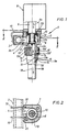
- the hot water valve 1 is attached to a hot water supply line 2 in a manner to be explained in more detail, wherein this hot water supply line 2 can be part of a conventional vending machine or part of a so-called distribution strip in vending machines.
- This hot water valve 1 contains a valve housing 3 with a hot water inlet 4, which is connected to the hot water supply line 2, as well as with a drain pipe 5 connected approximately vertically downwards to this valve housing 3. At the upper end of this drain pipe 5 is in the transition area from the interior 6 of the valve housing 3 a valve seat 7 is formed in the drain pipe 5.
- valve housing 3 On top of the valve housing 3 is an electrical actuating device 8 with a magnet armature which can be moved up and down in the direction of the double arrow 9a 9 attached, the lower end of which is designed in the form of a valve tappet 10, projects downward into the interior 6 of the valve housing 3 and carries a type of valve cone 11 at its free end.
- This valve cone 11 is designed such that it can be moved within the valve housing 3 with the aid of the actuating device 8 (and via magnet armature 9 and valve tappet 10) into a lower closed position against the valve seat 7.
- valve tappet 10 passing through the interior 6 of the valve housing 3, together with the valve cone 11, is surrounded by a sealing collar 12 made of resilient, rubber-elastic sealing material, the lower part 12a of this sealing collar 12 surrounding the valve cone 11 being significantly thickened in material compared to the material of the collar 12b.
- a throttle device in the form of a throttle collar 13 is arranged within the drain pipe 5 and is used to adjust the flow cross section of this drain pipe 5.
- the tubular throttle collar 13 is also made of rubber-elastic material, and it is designed in the middle section of its length - as can be seen in the drawing - in such a way that it can be changed using axial compression forces in its flow cross-section, whereby it then narrowed in the form of a Laval nozzle (with a variable free cross-section).
- the drain pipe 5 is divided into an upper pipe part 5a and a lower pipe part 5b, these two pipe parts 5a, 5b lying coaxially with each other.
- the throttle collar 13 is arranged as a type of connecting pipe piece, the two drain pipe parts 5a and 5b being connected to one another by a union nut 14, by this union nut 14 engaging under an upper, flange-like collar 5b ⁇ of the lower pipe part 5b and onto an external thread 5a ⁇ is screwed onto the lower end of the upper tube part 5a.
- the two drain pipe parts 5a and 5b can be adjusted in their axial relative position to one another in such a way that they exert axial compression forces on the two ends of the throttle collar 13, so that the flow cross section of the latter, as explained above, can be changed in the desired manner.
- the throttle collar 13 preferably has an inner diameter in the relaxed state which is approximately equal to the inner diameter of the drain pipe 5. Furthermore, in the mutually facing ends of the two drain pipe parts 5a and 5b - as indicated at 5c and 5d in Fig. 1 - machined recesses, in which the correspondingly shaped ends of the throttle collar 13 are received and held reliably.
- Fig. 1 it can also be seen that the upper The connecting end 5e of the lower drain pipe part 5b is expanded in its inner diameter and is designed such that it surrounds the throttle collar 13 to form an annular space 15.
- the throttle collar 13 has in the area of its waist 13a, preferably somewhat below this waist 13a, but in the area of the annular space 15 at least one, preferably a plurality of ventilation holes 16 distributed over the circumference.
- at least one (preferably several) axial ventilation channel 17 connecting the annular space 15 to the valve outside is provided on the outer peripheral side at the lower end of the upper drain pipe part 5a and within the region of the union nut 14 (i.e. on the part on which the external thread 5a ⁇ is provided) .
- the valve is emptied and splashing of the liquid when entering a drinking vessel is avoided with simple constructional means. Furthermore, since the ventilation holes 16 are arranged in the area of the narrowest cross-section of the (Venturi) nozzle that is being formed, namely in the area of the waist 13a of the throttle collar 13 (or shortly thereafter), contamination of the outflowing liquid is also certain to occur Interior of an associated vending machine or the associated hot water supply line 2 avoided.
- the throttle collar 13 and the sealing collar 12 can be produced from the same materials, in particular from rubber or rubber-like plastic material (e.g. silicone rubber).
- the interior 6 of the valve housing 3 is - as can be seen from a joint examination of FIGS. 1 and 2 - approximately in the form of a cylinder with a vertical axis 18, which simultaneously forms the vertical valve axis and which with the central axes of the valve lifter 10, the valve cone 11 , the valve seat 7 and the drain pipe 5 coincides.
- the hot water inlet 4 is preferably brought tangentially to the cylindrical interior 6 of the valve housing 3, as shown in FIG. This tangential assignment of the hot water inlet 4 to the valve housing interior 6 has the advantage that in the region above the valve cone 11 limescale is at least largely avoided by the fact that the Operating this valve 1 creates a potential vortex that complicates limescale deposits.
- the sealing sleeve 12 located in this valve housing interior 6 is also preferably designed such that it has a substantially cylindrical jacket 12b in the region of the valve tappet 10 in the form of a bellows which can be changed in its axial length (as indicated in FIG. 1) proceeding from the lower sleeve part 12a enclosing the valve cone 11 and thickened in the material.
- the upper end 12c of this sleeve jacket is then designed as an annular sealing flange which, together with the lower connecting end of the electrical actuating device 8, essentially seals the upper end of the interior 6 of the valve housing 3 in a sealing manner.
- this hot water valve 1 is detachably connected to the hot water line 2 in a very simple manner via a type of snap connection.
- the valve housing 3 has at least one spring-elastic clamp, but preferably - as shown in FIG. 2 - has two spring-elastic clamps 19 which can be inserted or held in bores 20 of the housing 3.
- These clips 19 include resiliently and in the manner of a snap connection at least a part of the hot water supply line 2 in such a way that a reliable Bracket of the whole hot water valve 1 is ensured on the supply line.
- the hot water inlet 4 of the valve 1 is sealingly connected to a connection opening 2a of the hot water supply line 2 with the interposition of a sealing ring 21.
- the spring-elastic clips 19 can be made of any suitable material, for example spring wire, spring band steel, spring-elastic plastic material (e.g. polyacetal or polycarbonate) or the like.
- valve cone (11) - as illustrated in Fig. 1 - has a particularly strong rounding at its corners.
Description
Die Erfindung betrifft ein Heißwasserventil zur Befestigung an einer Heißwasserzuführleitung, insbesondere für eine Verwendung bei Getränkeautomaten, gemäß dem Oberbegriff des Patentanspruches 1.The invention relates to a hot water valve for attachment to a hot water supply line, in particular for use in vending machines, according to the preamble of claim 1.
Heißwasserventile der vorausgesetzten Art sind aus der Praxis in verschiedenen Ausführungsformen bekannt. Insbesondere bei einer Verwendung an bzw. in Getränkeautomaten muß ein solches Ventil auf unterschiedliche Durchflußmengen einstellbar sein.Hot water valves of the required type are known in practice in various embodiments. Especially when used on or in vending machines, such a valve must be adjustable to different flow rates.
Dies wird üblicherweise dadurch erreicht, daß im Bereich des Abflußrohres oder direkt in diesem Abflußrohr eine Art Drosselschraube als Drosseleinrichtung eingebaut ist. Es hat sich nun gezeigt, daß eine solche Drosseleinrichtung sehr stark zum Verkalken neigt, was noch verstärkt wird, wenn durch eine solche Drosseleinrichtung der Durchflußquerschnitt unsymmetrisch verändert wird. Getränkeautomaten erfordern daher allein für das Heißwasserventil eine verstärkte laufende Wartung und Überwachung, was jedoch erheblichen Zeitaufwand und unerwünschte Stillstandszeiten mit sich bringt.This is usually achieved in that a type of throttle screw is installed as a throttle device in the area of the drain pipe or directly in this drain pipe. It has now been shown that such a throttle device has a very strong tendency to calcify, which is exacerbated when the flow cross section is changed asymmetrically by such a throttle device. Vending machines therefore require increased ongoing maintenance and monitoring for the hot water valve alone, but this entails considerable expenditure of time and undesirable downtimes.
Der Erfindung liegt daher die Aufgabe zugrunde, ein Heißwasserventil der im Oberbegriff des Patentanspruches 1 vorausgesetzten Art zu schaffen, das sich bei relativ einfacher Konstruktion und relativ leichter Anbaubarkeit vor allem dadurch auszeichnet, daß seine wesentlichen Teile sich weitgehend oder sogar vollkommen selbständig von Kalkablagerungen freihalten.The invention is therefore based on the object to provide a hot water valve of the type required in the preamble of claim 1, which is relatively simple in construction and relatively easy to install, characterized mainly by the fact that its essential parts are largely or even completely independent of limescale deposits.
Diese Aufgabe wird erfindungsgemäß durch die im Kennzeichen des Anspruches 1 angegebenen Merkmale gelöst.This object is achieved by the features specified in the characterizing part of claim 1.
Bei einem Heißwasserventil der vorausgesetzten Art neigen vor allem der Bereich Ventilkegel/Ventilsitz sowie die Drosseleinrichtung zu erhöhter Kalkablagerung. Erfindungsgemäß ist daher zum einem der Ventilstößel mitsamt seinem Ventilkegel von einer Dichtmanschette aus nachgiebigem, gummielastischem Dichtungsmaterial umgeben, das im Bereich des Ventilkegels verdickt ist. Bei dieser Ausführung bildet somit der den Ventilkegel umgebende Teil der Dichtmanschette gleichzeitig die Sitzdichtung gegenüber dem Ventilsitz innerhalb des Ventilgehäuses. Aufgrund der deutlichen Materialverdickung im Bereich des Ventilkegels erfolgt hier beim Schließen des Ventils eine verstärkte elastische Verformung, die zum Absprengen eines eventuell gebildeten Kalkansatzes in diesem Bereich führt.In the case of a hot water valve of the required type, the area of the valve cone / valve seat and the throttling device are particularly prone to increased limescale deposits. According to the invention, therefore, on the one hand, the valve tappet, together with its valve cone, is surrounded by a sealing collar made of flexible, rubber-elastic sealing material, which is thickened in the region of the valve cone. In this embodiment, the part of the sealing sleeve surrounding the valve cone thus simultaneously forms the seat seal with respect to the valve seat within the valve housing. Due to the significant thickening of material in the area of the valve cone, when the valve is closed there is an increased elastic deformation, which leads to a possible build-up of limescale in this area.
Zum anderen ist die Drosseleinrichtung erfindungsgemäß durch eine rohrförmige Drosselmanschette aus ebenfalls gummielastischem Material gebildet, die im mittleren Abschnitt ihrer Länge tailliert ausgeführt ist und unter Anwendung axialer Zusammendrückkräfte in ihrem Durchflußquerschnitt veränderbar ist. Diese erfindungsgemäß ausgebildete Taillierung führt in der Praxis dazu, daß bei einem axialen Zusammendrücken dieser Drosselmanschette deren Durchflußquerschnitt symmetrisch etwa in Form einer Venturidüse verengt wird, d.h. diese Drosselmanschette, die in ihrem entspannten Zustand eine etwa zylindrische, rohrförmige Gestalt besitzt, kann in Abhängigkeit von den auf sie angewendeten axialen Zusammendrückkräften kontinuierlich und stufenlos von ihrem vollen Durchflußquerschnitt bis zu einem nahezu oder vollkommen geschlossenen Durchflußquerschnitt verändert werden. Es ergibt sich dadurch nicht nur eine äußerst gute und feinfühlige Einstellmöglichkeit für unterschiedliche Heißwasser-Durchflußmengen, sondern gleichzeitig auch die Möglichkeit, Tendenzen zur Kalkablagerung an der Innenseite der Drosselmanschette deutlich herabzusetzen; falls überhaupt ein Kalkansatz an der Innenwand dieser Drosselmanschette auftreten sollte, dann kann dieser ohne Demontage der entsprechenden Ventilteile auf einfache Weise dadurch abgesprengtwerden, daß ganz bewußt die Dosselmanschette in axialer Richtung zusammengedrückt und dadurch deformiert wird.On the other hand, the throttle device according to the invention is formed by a tubular throttle collar made of rubber-elastic material, which is fitted in the middle section of its length and its flow cross-section can be changed using axial compression forces. This waist design according to the invention leads in practice to the fact that when this throttle collar is axially compressed, its flow cross-section is narrowed symmetrically approximately in the form of a Venturi nozzle, i.e. this throttle collar, which in its relaxed state has an approximately cylindrical, tubular shape, can be a function of the axial compression forces applied to them can be changed continuously and continuously from their full flow cross-section to an almost or completely closed flow cross-section. This not only results in an extremely good and sensitive setting option for different hot water flow rates, but also the possibility of significantly reducing tendencies towards limescale deposits on the inside of the throttle collar; if there is any limescale on the inner wall of this throttle collar, it can be easily blown off without dismantling the corresponding valve parts by deliberately compressing the throttle collar in the axial direction and deforming it.
Weitere Einzelheiten der Erfindung sind Gegenstand der Unteransprüche.Further details of the invention are the subject of the dependent claims.
Die Erfindung sei im folgenden anhand der Zeichnung näher beschrieben. In dieser Zeichnung zeigen
- Fig. 1
- eine zum Teil geschnittene Seitenansicht des an einer Zuführleitung befestigten Heißwasserventiles;
- Fig. 2
- eine Querschnittsansicht des Heißwasser- Ventiles etwa entlang der Linie II-II in Fig. 1.
- Fig. 1
- a partially sectioned side view of the hot water valve attached to a supply line;
- Fig. 2
- a cross-sectional view of the hot water valve approximately along the line II-II in Fig. 1st
Bei dem in der Zeichnung veranschaulichten Ausführungsbeispiel sei angenommen, daß das Heißwasserventil 1 an einer Heißwasserzuführleitung 2 in noch näher zu erläuternder Weise befestigt ist, wobei diese Heißwasserzuführleitung 2 Teil eines üblichen Getränkeautomaten oder Teil einer sogenannten Verteilerleiste bei Getränkeautomaten sein kann.In the exemplary embodiment illustrated in the drawing, it is assumed that the hot water valve 1 is attached to a hot water supply line 2 in a manner to be explained in more detail, wherein this hot water supply line 2 can be part of a conventional vending machine or part of a so-called distribution strip in vending machines.
Dieses Heißwasserventil 1 enthält ein Ventilgehäuse 3 mit einem Heißwassereinlauf 4, der an die Heißwasserzuführleitung 2 angeschlossen ist, sowie mit einem etwa vertikal an dieses Ventilgehäuse 3 nach unten angeschlossenen Abflußrohr 5. Am oberen Ende dieses Abflußrohres 5 ist im Übergangsbereich vom Innenraum 6 des Ventilgehäuses 3 in das Abflußrohr 5 ein Ventilsitz 7 ausgebildet.This hot water valve 1 contains a
Oben auf das Ventilgehäuse 3 ist eine elektrische Betätigungseinrichtung 8 mit einem in Richtung des Doppelpfeiles 9a auf- und abbewegbaren Magnetanker 9 befestigt, dessen unteres Ende in Form eines Ventilstößels 10 ausgebildet ist, nach unten in den Innenraum 6 des Ventilgehäuses 3 hineinragt und an seinem freien Ende eine Art Ventilkegel 11 trägt. Dieser Ventilkegel 11 ist so ausgebildet, daß er innerhalb des Ventilgehäuses 3 mit Hilfe der Betätigungseinrichtung 8 (und über Magnetanker 9 und Ventilstößel 10) in eine untere Verschlußstellung gegen den Ventilsitz 7 bewegt werden kann.On top of the
Der den Innenraum 6 des Ventilgehäuses 3 durchsetzende Ventilstößel 10 ist mitsamt dem Ventilkegel 11 von einer Dichtmanschette 12 aus nachgiebigem, gummielastischem Dichtungsmaterial umgeben, wobei der den Ventilkegel 11 umgebende untere Teil 12a dieser Dichtmanschette 12 im Material gegenüber dem Material des Manschettenmantels 12b deutlich verdickt ist.The valve tappet 10 passing through the interior 6 of the
Innerhalb des Abflußrohres 5 ist eine Drosseleinrichtung in Form einer Drosselmanschette 13 angeordnet, die zum Einstellen des Durchflußquerschnittes dieses Abflußrohres 5 dient. Die rohrförmige Drosselmanschette 13 ist ebenfalls aus gummielastischem Material hergestellt, und sie ist im mittleren Abschnitt ihrer Länge - wie in der Zeichnung zu erkennen ist - tailliert ausgeführt, und zwar derart, daß sie unter Anwendung axialer Zusammendrückkräfte in ihrem Durchflußquerschnitt veränderbar ist, wobei sie sich dann in Form einer Lavaldüse verengt (bei veränderlichem freien Querschnitt).A throttle device in the form of a
Wie in Fig. 1 zu erkennen ist, ist das Abflußrohr 5 in einen oberen Rohrteil 5a und einen unteren Rohrteil 5b unterteilt, wobei diese beiden Rohrteile 5a, 5b koaxial untereinanderliegen. Zwischen diesen beiden Abflußrohrteilen 5a und 5b ist die Drosselmanschette 13 als eine Art Verbindungsrohrstück angeordnet, wobei die beiden Abflußrohrteile 5a und 5b durch eine Überwurfmutter 14 miteinander verbunden, indem diese Überwurfmutter 14 einen oberen, flanschartigen Bund 5bʹ des unteren Rohrteiles 5b untergreift und auf ein Außengewinde 5aʹ am unteren Ende des oberen Rohrteiles 5a aufgeschraubt ist. Durch diese Verbindung können die beiden Abflußrohrteile 5a und 5b in ihrer axialen Relativlage zueinander derart verstellt werden, daß sie axiale Zusammendrückkräfte auf die beiden Stirnenden der Drosselmanschette 13 ausüben, so daß letztere - wie oben erläutert - in ihrem Durchflußquerschnitt in gewünschter Weise veränderbar ist.As can be seen in Fig. 1, the
Die Drosselmanschette 13 weist vorzugsweise im entspannten Zustand einen Innendurchmesser auf, der etwa gleich dem Innendurchmesser des Abflußrohres 5 ist. Ferner sind in die gegeneinander weisenden Stirnenden der beiden Abflußrohrteile 5a und 5b -wie bei 5c bzw. 5d in Fig. 1 angedeutet - Formausdrehungen eingearbeitet, in denen die entsprechend geformten Stirnenden der Drosselmanschette 13 aufgenommen und zuverlässig gehaltert sind.The
In Fig. 1 ist ferner zu erkennen, daß das obere Verbindungsende 5e des unteren Abflußrohrteiles 5b in seinem Innendurchmesser derart erweitert und so ausgebildet ist, daß es die Drosselmanschette 13 unter Bildung eines Ringraumes 15 umgibt. Die Drosselmanschette 13 weist hierbei im Bereich ihrer Taillierung 13a, und zwar vorzugsweise etwas unterhalb dieser Taillierung 13a, jedoch im Bereich des Ringraumes 15 wenigstens ein, vorzugsweise mehrere über den Umfang verteilte Belüftungslöcher 16 auf. Ferner ist auf der Außenumfangsseite am unteren Ende des oberen Abflußrohrteiles 5a sowie innerhalb des Bereiches der Überwurfmutter 14 (also an dem Teil, an dem das Außengewinde 5aʹ vorgesehen ist) wenigstens ein (vorzugsweise mehrere) den Ringraum 15 mit der Ventilaußenseite verbindender axialer Belüfungskanal 17 vorgesehen.In Fig. 1 it can also be seen that the upper The connecting end 5e of the lower
Durch diese von den Belüftungslöchern 16, den Ringraum 15 und die Belüftungskanäle 17 gebildete Belüftungsverbindung zwischen dem Innern des Abflußrohres 5 und der Ventilaußenseite wird ein Leerlaufen des Ventiles erreicht und ein Spritzen der Flüssigkeit beim Einlaufen in ein Trinkgefäß mit einfachen konstruktiven Mitteln vermieden. Da ferner die Belüfungslöcher 16 im Bereich des engsten Querschnittes der sich bildenden(Venturi-)Düse, nämlich im Bereich der Taillierung 13a der Drosselmanschette 13 (bzw. kurz danach) angeordnet sind, wird auch mit Sicherheit bei einem Rückstau der abfließenden Flüssigkeit eine Verunreinigung des Geräteinnern eines zugehörigen Getränkeautomaten bzw. der zugehörigen Heißwasserzuführleitung 2 vermieden.Through this ventilation connection formed by the
Eine besonders einfache Bedienung, d. h. ohne Verwendung zusätzlicher Hilfsmittel oder Werkzeuge für eine Veränderung des Durchflußquerschnittes der Drosselmanschette 13 kann vor allem dadurch erreicht werden, daß die Überwurfmutter 14 als leicht zu bedienende Rändel-Überwurfmutter ausgebildet ist.A particularly simple operation, i. H. Without using additional aids or tools for changing the flow cross section of the
Die Drosselmanschette 13 und die Dichtmanschette 12 können aus gleichen Materialien hergestellt sein, insbesondere aus Gummi oder gummiartigem Kunststoffmaterial (z. B. Silikonkautschuk).The
Der Innenraum 6 des Ventilgehäuses 3 ist - wie eine gemeinsame Betrachtung der Fig. 1 und 2 erkennen läßt - etwa in Form eines Zylinders mit vertikaler Achse 18 ausgeführt, die gleichzeitig die vertikale Ventilachse bildet und die mit den Mittelachsen des Ventilstößels 10,des Ventilkegels 11, des Ventilsitzes 7 und des Abflußrohres 5 zusammenfällt. Der Heißwassereinlauf 4 ist dabei vorzugsweise tangential an den zylindrischen Innenraum 6 des Ventilgehäuses 3 herangeführt, wie Fig.2 zeigt. Diese tangentiale Zuordnung des Heißwassereinlaufes 4 zum Ventilgehäuse-Innenraum 6 hat den Vorteil, daß im Bereich oberhalb des Ventilkegels 11 Kalkablagerung dadurch zumindest weitgehend vermieden werden, daß beim Betätigen dieses Ventiles 1 ein Potentialwirbel entsteht, der Kalkablagerungen erschwert.The interior 6 of the
Die in diesem Ventilgehäuse-Innenraum 6 befindliche Dichtmanschette 12 ist ferner vorzugsweise so ausgebildet, daß sie im Bereich des Ventilstößels 10 einen im wesentlichen zylindrischen Mantel 12b in Form eines in seiner axialen Länge veränderbaren Faltenbalges (wie in Fig. 1 angedeutet) aufweist, und zwar ausgehend von dem den Ventilkegel 11 umschließenden, im Material verdickten unteren Manschettenteil 12a. Hierbei ist dann das obere Ende 12c dieses Manschettenmantels als ringförmiger Dichtungsflansch ausgebildet, der - zusammen mit dem unteren Verbindungsende der elektrischen Betätigungseinrichtung 8 - im wesentlichen das obere Ende vom Innenraum 6 des Ventilgehäuses 3 dichtend abschließt.The sealing sleeve 12 located in this valve housing interior 6 is also preferably designed such that it has a substantially cylindrical jacket 12b in the region of the valve tappet 10 in the form of a bellows which can be changed in its axial length (as indicated in FIG. 1) proceeding from the lower sleeve part 12a enclosing the valve cone 11 and thickened in the material. The
Wie weiter oben bereits angedeutet wurde, ist dieses Heißwasserventil 1 auf äußerst einfache Weise über eine Art Schnappverbindung lösbar mit der Heißwasserleitung 2 verbunden. Für diese Schnappverbindung weist das Ventilgehäuse 3 wenigstens eine federelastische Klammer, vorzugsweise - wie Fig. 2 zeigt - jedoch zwei federelastische Klammern 19 auf, die in Bohrungen 20 des Gehäuses 3 eingesteckt bzw. gehaltert sein können. Diese Klammern 19 umfassen federelastisch und nach Art einer Schnappverbindung zumindest einen Teil der Heißwasserzuführleitung 2 derart, daß eine zuverlässige Halterung des ganzen Heißwasserventiles 1 an der Zuführleitung sichergestellt ist. Hierbei ist der Heißwassereinlauf 4 des Ventiles 1 unter Zwischenanordnung eines Dichtringes 21 dichtend an eine Anschlußöffnung 2a der Heißwasserzuführleitung 2 angeschlossen.As has already been indicated above, this hot water valve 1 is detachably connected to the hot water line 2 in a very simple manner via a type of snap connection. For this snap connection, the
Die Federelastischen Klammern 19 können aus jedem geeigneten Material hergestellt sein, beispielsweise aus Federdraht, Federbandstahl, federelastischem Kunststoffmaterial (z. B. Polyazetal oder Polykarbonat) oder dergleichen.The spring-
Schließlich sei noch hinzugefügt, daß die verhältnismäßig dicke Ausbildung des gummielastischen Materiales am Ventilkegel dadurch besonders begünstigt werden kann, daß dieser Ventilkegel (11) - wie in Fig. 1 veranschaulicht - an seinen Ecken eine besonders starke Verrundung aufweist.Finally, it should be added that the relatively thick formation of the rubber-elastic material on the valve cone can be particularly favored in that this valve cone (11) - as illustrated in Fig. 1 - has a particularly strong rounding at its corners.
Claims (8)
- Hot water valve for fixing on a hot water supply pipe, particularly for use in automatic drink dispensers, comprisinga) a valve housing (3) with a hot water inlet (4) and an approximately vertical discharge pipe (5),b) a valve seat (7) constructed at the upper end of the discharge pipe (5) in the valve housing (3),c) a valve stem (10) connected to an actuating device (8) and with a valve cone (11) which is movable within the valve housing into a rest position against the valve seat (7),d) a throttle arrangement (13) arranged within the discharge pipe (5) for adjusting the through flow crosssection of this pipe,characterised by the following features:e) the valve stem (10) which passes through the valve housing (3) is enclosed together with the valve cone (11) by a sealing sleeve (12) which is made from flexible elastic rubber sealing material which is thicker in the region of the valve cone;f) the throttle arrangement is formed by a tubular throttle sleeve (13) made from elastic rubber material which is waisted in the central section of its length and can be varied in its through flow crosssection by the use of axial compression forces.
- Hot water valve as claimed in claim 1, characterised in that the discharge pipe (5) is divided in two and the tubular throttle sleeve (13) is arranged between the two discharge pipe parts (5a, 5b) as a type of connecting pipe section, and the two discharge pipe parts (5a, 5b) are connected by a coupling nut (14) and can be adjusted in their axial position relative to one another in such a way that they exert axial compression forces on the two ends of the throttle sleeve (13).
- Hot water valve as claimed in claim 2, characterised in that the throttle sleeve (13) in the relaxed state has an internal diameter which is approximately equal to the internal diameter of the discharge pipe (5), and that bores (5c, 5d) are machined into the ends of the discharge pipe parts (5a, 5b) to receive the ends of the throttle sleeve.
- Hot water valve as claimed in claim 2, characterised in that the internal diameter of the upper connecting end (5e) of the lower discharge pipe part (5b) is widened and constructed in such a way that it surrounds the throttle sleeve (13), forming an annular space (15), the throttle sleeve (13) has at least one radial ventilation hole (16) in the region of the waisting (13a) and of the annular space (15), and at least one ventilation channel (17) connecting the annular space (15) to the outside of the valve is provided on the outer peripheral face at the lower end of the upper discharge pipe part (5a) as well as inside the coupling nut (14).
- Hot water valve as claimed in claim 2, characterised in that the coupling nut is constructed as a knurled coupling nut (14).
- Hot water valve as claimed in claim 1, characterised in that the interior (6) of the valve housing (3) is constructed approximately in the form of a cylinder with a vertical axis (18) which coincides with the central axes of the valve stem (10), valve cone (11), valve seat (7) and discharge pipe (5), and the hot water inlet is led tangentially to this cylindrical interior (6).
- Hot water valve as claimed in claims 1 and 6, characterised in that the valve housing (3) has at least one resilient clip (19) for a releasable snap connection to the hot water supply pipe (2).
- Hot water valve as claimed in claim 6, characterised in that in the region of the valve stem (10) the sealing sleeve (12) has a substantially cylindrical sheath (12b) in the form of a bellows which is variable in its axial length, the upper end (12c) of this sleeve sheath being constructed as an annular sealing flange which essentially closes and seals the upper end of the interior (6) of the valve housing (3).
Applications Claiming Priority (2)
| Application Number | Priority Date | Filing Date | Title |
|---|---|---|---|
| DE3643123 | 1986-12-17 | ||
| DE19863643123 DE3643123A1 (en) | 1986-12-17 | 1986-12-17 | HOT WATER VALVE |
Publications (3)
| Publication Number | Publication Date |
|---|---|
| EP0271771A2 EP0271771A2 (en) | 1988-06-22 |
| EP0271771A3 EP0271771A3 (en) | 1989-06-14 |
| EP0271771B1 true EP0271771B1 (en) | 1991-07-17 |
Family
ID=6316410
Family Applications (1)
| Application Number | Title | Priority Date | Filing Date |
|---|---|---|---|
| EP87117807A Expired - Lifetime EP0271771B1 (en) | 1986-12-17 | 1987-12-02 | Hot water valve |
Country Status (3)
| Country | Link |
|---|---|
| EP (1) | EP0271771B1 (en) |
| DE (2) | DE3643123A1 (en) |
| DK (1) | DK666987A (en) |
Cited By (3)
| Publication number | Priority date | Publication date | Assignee | Title |
|---|---|---|---|---|
| DE10317455A1 (en) * | 2003-04-16 | 2004-11-11 | Danfoss A/S | Hot water valve for an automated drinks machine comprises an inlet and an outlet which are made from plastic on their surfaces in contact with water |
| DE10357590A1 (en) * | 2003-12-08 | 2005-08-18 | Danfoss A/S | Hot water valve especially for beverage dispenser has conical valve element and seat made of different metals and with an impact closure action which prevents accumulation of calcium carbonate |
| WO2008049162A1 (en) * | 2006-10-24 | 2008-05-02 | Brando International Limited | Protective sheath |
Families Citing this family (7)
| Publication number | Priority date | Publication date | Assignee | Title |
|---|---|---|---|---|
| GB2241773A (en) * | 1990-03-06 | 1991-09-11 | Thomas Robert Edward Bellew | Water-saving hot water supply |
| CN2463624Y (en) * | 2001-02-12 | 2001-12-05 | 周世友 | Leakless valve |
| US20070114480A1 (en) * | 2005-11-23 | 2007-05-24 | Burke Joseph M | Vorticity generators for use with fluid control systems |
| CN103470794B (en) * | 2013-09-13 | 2016-06-22 | 吴江市东吴机械有限责任公司 | Import and export double linkage changeover valve |
| CN103591334A (en) * | 2013-11-22 | 2014-02-19 | 吴江市东吴机械有限责任公司 | Inlet and outlet double linkage changeover valve |
| CN105299311B (en) * | 2015-10-26 | 2018-02-13 | 厦门欧替埃电子工业有限公司 | A kind of stop valve applied to silica gel pipeline |
| CN113944759B (en) * | 2021-10-19 | 2023-10-13 | 西安长峰机电研究所 | Self-deposition integrated hot gas two-phase separation flow regulating valve |
Family Cites Families (6)
| Publication number | Priority date | Publication date | Assignee | Title |
|---|---|---|---|---|
| DE1151520B (en) * | 1959-11-27 | 1963-07-18 | C Herbert Zikesch Dipl Ing | Device for throttling and cooling of steam |
| AT237981B (en) * | 1960-08-01 | 1965-01-25 | American Radiator & Standard | Liquid tap |
| US3179124A (en) * | 1962-10-15 | 1965-04-20 | John M Haring | Valve |
| US3528087A (en) * | 1968-03-25 | 1970-09-08 | Robertshaw Controls Co | Packless valve construction |
| DE2113394A1 (en) * | 1971-03-19 | 1972-09-21 | Zentra Albret Buerkle Kg | Valve |
| US4088297A (en) * | 1976-11-03 | 1978-05-09 | Bradley Corporation | Timed metering valve |
-
1986
- 1986-12-17 DE DE19863643123 patent/DE3643123A1/en not_active Withdrawn
-
1987
- 1987-12-02 DE DE8787117807T patent/DE3771461D1/en not_active Expired - Fee Related
- 1987-12-02 EP EP87117807A patent/EP0271771B1/en not_active Expired - Lifetime
- 1987-12-17 DK DK666987A patent/DK666987A/en not_active Application Discontinuation
Cited By (5)
| Publication number | Priority date | Publication date | Assignee | Title |
|---|---|---|---|---|
| DE10317455A1 (en) * | 2003-04-16 | 2004-11-11 | Danfoss A/S | Hot water valve for an automated drinks machine comprises an inlet and an outlet which are made from plastic on their surfaces in contact with water |
| DE10317455B4 (en) * | 2003-04-16 | 2005-07-14 | Danfoss A/S | Hot water valve |
| DE10357590A1 (en) * | 2003-12-08 | 2005-08-18 | Danfoss A/S | Hot water valve especially for beverage dispenser has conical valve element and seat made of different metals and with an impact closure action which prevents accumulation of calcium carbonate |
| DE10357590B4 (en) * | 2003-12-08 | 2006-04-20 | Danfoss A/S | Hot water valve |
| WO2008049162A1 (en) * | 2006-10-24 | 2008-05-02 | Brando International Limited | Protective sheath |
Also Published As
| Publication number | Publication date |
|---|---|
| DE3771461D1 (en) | 1991-08-22 |
| EP0271771A3 (en) | 1989-06-14 |
| DE3643123A1 (en) | 1988-06-30 |
| DK666987D0 (en) | 1987-12-17 |
| EP0271771A2 (en) | 1988-06-22 |
| DK666987A (en) | 1988-06-18 |
Similar Documents
| Publication | Publication Date | Title |
|---|---|---|
| EP1134468A2 (en) | Sanitary fitting | |
| EP0271771B1 (en) | Hot water valve | |
| EP0358882B1 (en) | Discharge valve with ball joint arrangement | |
| DE202017100423U1 (en) | Hose connection arrangement, use of a hose connection arrangement and sanitary fitting | |
| EP1600839B1 (en) | Flow regulator | |
| DE102017101566B3 (en) | Hose connection arrangement, use of a hose connection arrangement and sanitary fitting | |
| DE2609170C2 (en) | Mixer tap changer | |
| EP3730705B1 (en) | Sanitary valve | |
| EP0187378B2 (en) | Thermostatic valve | |
| EP0080591A1 (en) | Connecting device for sanitary installations with a flexible conduit and joining pieces on both ends | |
| DE2407933A1 (en) | DIVERTING VALVE FOR SHOWER BATH TAP | |
| EP2530365A1 (en) | Valve insert for a sanitary fitting | |
| EP0581192B1 (en) | Shower-diverter for sanitary fitting | |
| DE3006660C2 (en) | Shower head attachable to a water outlet with an adjustment device for two jet types | |
| DE2705165A1 (en) | FITTINGS, IN PARTICULAR MIXING TAP WITH MANUAL REGULATION | |
| EP1212563A1 (en) | Insert valve for a sectional radiator | |
| EP1239238A1 (en) | Connecting fitting for a radiator | |
| DE3834997C2 (en) | ||
| EP0982441B1 (en) | Sanitary single-handle faucet | |
| DE873640C (en) | Cock, especially milk cock | |
| DE3743707C2 (en) | Valve with preset flow rate | |
| DE1296910B (en) | Tap for mixing two liquids | |
| DE3344614A1 (en) | Adaptor for connecting a water outlet fitting to a water outlet of non-standard connection cross-section | |
| DE4443895A1 (en) | Sanitary fitting | |
| DE3209297C2 (en) |
Legal Events
| Date | Code | Title | Description |
|---|---|---|---|
| PUAI | Public reference made under article 153(3) epc to a published international application that has entered the european phase |
Free format text: ORIGINAL CODE: 0009012 |
|
| AK | Designated contracting states |
Kind code of ref document: A2 Designated state(s): DE FR IT |
|
| PUAL | Search report despatched |
Free format text: ORIGINAL CODE: 0009013 |
|
| AK | Designated contracting states |
Kind code of ref document: A3 Designated state(s): DE FR IT |
|
| 17P | Request for examination filed |
Effective date: 19890921 |
|
| 17Q | First examination report despatched |
Effective date: 19901203 |
|
| GRAA | (expected) grant |
Free format text: ORIGINAL CODE: 0009210 |
|
| ITF | It: translation for a ep patent filed |
Owner name: ING. FERRAROTTI GIOVANNI |
|
| AK | Designated contracting states |
Kind code of ref document: B1 Designated state(s): DE FR IT |
|
| REF | Corresponds to: |
Ref document number: 3771461 Country of ref document: DE Date of ref document: 19910822 |
|
| ET | Fr: translation filed | ||
| PLBE | No opposition filed within time limit |
Free format text: ORIGINAL CODE: 0009261 |
|
| STAA | Information on the status of an ep patent application or granted ep patent |
Free format text: STATUS: NO OPPOSITION FILED WITHIN TIME LIMIT |
|
| 26N | No opposition filed | ||
| PG25 | Lapsed in a contracting state [announced via postgrant information from national office to epo] |
Ref country code: FR Effective date: 19920831 |
|
| PG25 | Lapsed in a contracting state [announced via postgrant information from national office to epo] |
Ref country code: DE Effective date: 19920901 |
|
| REG | Reference to a national code |
Ref country code: FR Ref legal event code: ST |
|
| PG25 | Lapsed in a contracting state [announced via postgrant information from national office to epo] |
Ref country code: IT Free format text: LAPSE BECAUSE OF NON-PAYMENT OF DUE FEES;WARNING: LAPSES OF ITALIAN PATENTS WITH EFFECTIVE DATE BEFORE 2007 MAY HAVE OCCURRED AT ANY TIME BEFORE 2007. THE CORRECT EFFECTIVE DATE MAY BE DIFFERENT FROM THE ONE RECORDED. Effective date: 20051202 |