EP0271740A2 - Device for switching an apparatus mounted in a vehicle on or off - Google Patents
Device for switching an apparatus mounted in a vehicle on or off Download PDFInfo
- Publication number
- EP0271740A2 EP0271740A2 EP87117189A EP87117189A EP0271740A2 EP 0271740 A2 EP0271740 A2 EP 0271740A2 EP 87117189 A EP87117189 A EP 87117189A EP 87117189 A EP87117189 A EP 87117189A EP 0271740 A2 EP0271740 A2 EP 0271740A2
- Authority
- EP
- European Patent Office
- Prior art keywords
- switching
- ignition lock
- switching device
- ignition
- arrangement according
- Prior art date
- Legal status (The legal status is an assumption and is not a legal conclusion. Google has not performed a legal analysis and makes no representation as to the accuracy of the status listed.)
- Granted
Links
Images
Classifications
-
- B—PERFORMING OPERATIONS; TRANSPORTING
- B60—VEHICLES IN GENERAL
- B60R—VEHICLES, VEHICLE FITTINGS, OR VEHICLE PARTS, NOT OTHERWISE PROVIDED FOR
- B60R16/00—Electric or fluid circuits specially adapted for vehicles and not otherwise provided for; Arrangement of elements of electric or fluid circuits specially adapted for vehicles and not otherwise provided for
- B60R16/02—Electric or fluid circuits specially adapted for vehicles and not otherwise provided for; Arrangement of elements of electric or fluid circuits specially adapted for vehicles and not otherwise provided for electric constitutive elements
- B60R16/023—Electric or fluid circuits specially adapted for vehicles and not otherwise provided for; Arrangement of elements of electric or fluid circuits specially adapted for vehicles and not otherwise provided for electric constitutive elements for transmission of signals between vehicle parts or subsystems
Definitions
- the invention relates to an arrangement for switching on or off a device operated in a motor vehicle, in particular a car radio, consisting of a switching device which can be actuated with the ignition lock of the motor vehicle and a switching device arranged in the device itself.
- connection options for a car radio in a motor vehicle Either the device is connected to a constantly live line or it is connected to a line in which the power supply can be interrupted by the ignition lock of the motor vehicle.
- the first possibility has the disadvantage that the device must always be operated again at the start and end of the trip via the switch arranged in the device, it being very easy to forget to switch off when leaving the vehicle and the vehicle battery is thereby unnecessarily discharged.
- the ignition lock has a so-called “park” position, in which the power supply to the connected device is established without switching on the ignition.
- the ignition key is usually not removable in this position. For children left behind in the car who, for example, For example, hearing a cassette poses a significant risk. Even if the key could be removed, this could often be forgotten.
- the invention has for its object to provide an arrangement of the type specified in the preamble of claim 1 so that even when the "lock" position of the ignition lock is omitted, the device operated in the vehicle can be switched on and off via the ignition lock and secondly the ignition switch position "Off" can be operated.
- the switching device coupled to the ignition lock delivers a logic level corresponding to the respective position of the ignition lock at its output. Furthermore, a bistable flip-flop circuit is provided, which changes its switching state each time the switching device arranged in the device itself is actuated and also supplies a logic level corresponding to the respective switching state at its output.
- the digital signals supplied by the switching device of the ignition lock and by the bistable multivibrator are linked via a switching logic which generates the control signal necessary for switching the device on and off.
- the switching logic provided is advantageously designed such that the device to be operated can be switched on and off independently of the position of the ignition lock by means of the switching device arranged in the device itself.
- the power supply to the device is basically interrupted when the ignition lock is switched from the "on” to the "off” position (switching off the vehicle engine), while when the ignition lock is switched from the "off” to the “on” position the original operating state of the device is restored. For example, if the device was switched on before the vehicle engine was switched off, this operating state is restored when the engine is started again. Accordingly, both the switching position and the switching direction of the ignition lock, as well as the switching position of the bistable flip-flop circuit arranged in the device, are evaluated via the switching logic and, depending on this, the control signal necessary for switching the device on and off is generated.
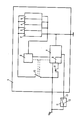
- the figure shows a device 1 to be operated in a motor vehicle, consisting of a receiving part 2, a cassette part 3, an LF part 4 and a lighting device 5.
- the device is on the one hand and on the other hand via an ignition lock 11 with the battery voltage U B connected.
- the ignition lock 11 has only two positions and is coupled to a switching device 12.
- the battery voltage U B leads via a switch 10, which can be controlled by a switching logic 7 and a timer circuit 6, to the device circuits 2 to 5 to be supplied.
- the switching logic includes a bistable multivibrator 8, e.g. B. a flip-flop, integrated, the switching state can be changed via a switching device 9, in such a way that the switching state of the flip-flop 8 changes each time the switching device 9 is actuated.
- the switching logic 7 determines the position of the ignition lock 11 via the output 13 of the switching device 12.
- the switching logic 7 is thus available to the switching logic 7 via the switching device 12 and the flip-flop 8 and, with a corresponding logical combination, controls the desired switching functions.
- the logical combination of the two digital signals can be done either by a suitable arrangement of gates or by program-controlled software using a microprocessor.
- the time circuit 6 provided in the exemplary embodiment advantageously leaves the device 1 in the switched-on state only for a predetermined time.
- the relevant time circuit is only activated when certain digital signals are linked, for example when the output 13 of the switching device 12 is at a "low level” and the switching position of the flip-flop 8 is activated by actuating the switching device 9 from “low”. goes to "high”.
- the ignition lock is in the "off” position and the device is switched on via the switching device 9.
- the switching device 9 is preferably designed as a non-latching tip button, which replaces the conventional current-operated operating voltage switch and z. B. can be arranged on the volume control of the device 1.
Abstract
Description
Die Erfindung betrifft eine Anordnung zum Ein- bzw. Ausschalten eines in einem Kraftfahrzeug betriebenen Gerätes, insbesondere eines Autoradios, bestehend aus einer mit dem Zündschloss des Kraftfahrzeugs betätigbaren Schalteinrichtung sowie einer im Gerät selbst angeordneten Schalteinrichtung.The invention relates to an arrangement for switching on or off a device operated in a motor vehicle, in particular a car radio, consisting of a switching device which can be actuated with the ignition lock of the motor vehicle and a switching device arranged in the device itself.
Grundsätzlich bestehen in einem Kraftfahrzeug zwei Anschlußmöglichkeiten für ein Autoradio. Entweder das Gerät wird an eine ständig stromführende Leitung angeschlossen oder es wird mit einer Leitung verbunden, bei der die Stromzufuhr durch das Zündschloß des Kraftfahrzeuges unterbrochen werden kann. Die erste Möglichkeit hat den Nachteil, daß das Gerät bei Fahrtantritt und Fahrtende stets über den im Gerät angeordneten Schalter neu bedient werden muß, wobei das Abschalten beim Verlassen des Fahrzeugs sehr leicht vergessen werden kann und die Fahrzeugbatterie hierdurch unnötig entladen wird.Basically, there are two connection options for a car radio in a motor vehicle. Either the device is connected to a constantly live line or it is connected to a line in which the power supply can be interrupted by the ignition lock of the motor vehicle. The first possibility has the disadvantage that the device must always be operated again at the start and end of the trip via the switch arranged in the device, it being very easy to forget to switch off when leaving the vehicle and the vehicle battery is thereby unnecessarily discharged.
Dieser Nachteil wird durch die zweite Anschlußmöglichkeit zwar umgangen, da das über den Zündschalter angeschlossene Gerät bei der Zündschloß-Stellung "Aus" automatisch stromlos wird. Für den Betrieb des Gerätes bei abgeschaltetem Motor weist das Zündschloß eine sogenannte "Park"-Stellung auf, bei der die Stromzufuhr zu dem angeschlossenen Gerät hergestellt wird, ohne die Zündung einzuschalten. Der Zündschlüssel ist in dieser Stellung in der Regel jedoch nicht abziehbar. Bei im Auto zurückgelassenen Kindern, die während der Abwesenheit der Eltern z. B. eine Cassette hören, stellt dies ein erhebliches Risiko dar. Auch wenn der Schlüssel abziehbar wäre, so könnte dies häufig vergessen werden.This disadvantage is avoided by the second connection option, since the device connected via the ignition switch is automatically de-energized when the ignition switch is in the "off" position. For the operation of the device with the engine switched off, the ignition lock has a so-called “park” position, in which the power supply to the connected device is established without switching on the ignition. However, the ignition key is usually not removable in this position. For children left behind in the car who, for example, For example, hearing a cassette poses a significant risk. Even if the key could be removed, this could often be forgotten.
Der Erfindung liegt die Aufgabe zugrunde, eine Anordnung der im Oberbegriff des Anspruchs 1 angegebenen Art so auszubilden, daß auch bei entfallender "Park"-Stellung des Zündschlosses das im Fahrzeug betriebene Gerät zum einen über das Zündschloß ein- und ausschaltbar ist und zum anderen bei der Zündschloß-Stellung "Aus" betrieben werden kann.The invention has for its object to provide an arrangement of the type specified in the preamble of claim 1 so that even when the "lock" position of the ignition lock is omitted, the device operated in the vehicle can be switched on and off via the ignition lock and secondly the ignition switch position "Off" can be operated.
Diese Aufgabe wird gemäß der Erfindung durch die im Kennzeichen des Patentanspruchs 1 angegebenen Merkmale gelöst. Vorteilhafte Ausgestaltungen der Erfindung sind in den Unteransprüchen gekennzeichnet.This object is achieved according to the invention by the features specified in the characterizing part of patent claim 1. Advantageous embodiments of the invention are characterized in the subclaims.
Bei der Anordnung gemäß der Erfindung liefert die mit dem Zündschloß gekoppelte Schalteinrichtung an ihrem Ausgang einen der jeweiligen Stellung des Zündschlosses entsprechenden logischen Pegel. Ferner ist eine bistabile Kippschaltung vorgesehen, die bei jeder Betätigung der im Gerät selbst angeordneten Schalteinrichtung ihren Schaltzustand ändert und an ihrem Ausgang ebenfalls einen dem jeweiligen Schaltzustand entsprechenden logischen Pegel liefert. Die von der Schalteinrichtung des Zündschlosses sowie die von der bistabilen Kippschaltung gelieferten digitalen Signale sind über eine Schaltlogik verknüpft, die das zum Ein- bzw. Ausschalten des Gerätes notwendige Steuersignal generiert.In the arrangement according to the invention, the switching device coupled to the ignition lock delivers a logic level corresponding to the respective position of the ignition lock at its output. Furthermore, a bistable flip-flop circuit is provided, which changes its switching state each time the switching device arranged in the device itself is actuated and also supplies a logic level corresponding to the respective switching state at its output. The digital signals supplied by the switching device of the ignition lock and by the bistable multivibrator are linked via a switching logic which generates the control signal necessary for switching the device on and off.
Die vorgesehene Schaltlogik ist in vorteilhafter Weise so ausgelegt, daß das zu betreibende Gerät ,mittels der im Gerät selbst angeordneten Schalteinrichtung unabhängig von der Stellung des Zündschlosses ein- und ausschaltbar ist. Ferner wird die Stromzufuhr zu dem Gerät beim Umstellen des Zündschlosses von der "Ein"- in die "Aus"-Stellung (Abstellen des Fahrzeugmotors) grundsätzlich unterbrochen, während beim Umstellen des Zündschlosses von der "Aus"- in die "Ein"-Stellung der ursprüngliche Betriebszustand des Gerätes wieder hergestellt wird. War zum Beispiel das Gerät vor dem Abstellen des Fahrzeugmotors eingeschaltet, so wird dieser Betriebszustand beim erneuten Starten des Motors wieder hergestellt. Demnach wird über die Schaltlogik sowohl die Schaltstellung und die Schaltrichtung des Zündschlosses, als auch die Schaltstellung der im Gerät angeordneten bistabilen Kippschaltung ausgewertet und hiervon abhängig das zum Ein- bzw. Ausschalten des Gerätes notwendige Steuersignal generiert.The switching logic provided is advantageously designed such that the device to be operated can be switched on and off independently of the position of the ignition lock by means of the switching device arranged in the device itself. Furthermore, the power supply to the device is basically interrupted when the ignition lock is switched from the "on" to the "off" position (switching off the vehicle engine), while when the ignition lock is switched from the "off" to the "on" position the original operating state of the device is restored. For example, if the device was switched on before the vehicle engine was switched off, this operating state is restored when the engine is started again. Accordingly, both the switching position and the switching direction of the ignition lock, as well as the switching position of the bistable flip-flop circuit arranged in the device, are evaluated via the switching logic and, depending on this, the control signal necessary for switching the device on and off is generated.
Ein Ausführungsbeispiel der Erfindung ist im folgenden anhand einer Zeichnung näher erläutert.An embodiment of the invention is explained in more detail below with reference to a drawing.
Die Figur zeigt ein in einem Kraftfahrzeug zu betreibendes Gerät 1, bestehend aus einem Empfangsteil 2, einem Cassettenteil 3, einem NF-Teil 4 und einer Beleuchtungseinrichtung 5. Das Gerät ist zum einen direkt und zum anderen über ein Zündschloß 11 mit der Batteriespannung UB verbunden. Das Zündschloß 11 verfügt lediglich über zwei Stellungen und ist mit einer Schalteinrichtung 12 gekoppelt. Die Batteriespannung UB führt über einen von einer Schaltlogik 7 und einer Zeitschaltung 6 steuerbaren Schalter 10 zu den zu versorgenden Geräteschaltungen 2 bis 5. In die Schaltlogik ist eine bistabile Kippschaltung 8, z. B. ein Flip-Flop, integriert, dessen Schaltzustand über eine Schalteinrichtung 9 veränderbar ist, und zwar so, daß sich bei jeder Betätigung der Schalteinrichtung 9 der Schaltzustand des Flip-Flop 8 ändert. Die Stellung des Zündschlosses 11 ermittelt die Schaltlogik 7 über den Ausgang 13 der Schalteinrichtung 12.The figure shows a device 1 to be operated in a motor vehicle, consisting of a receiving
Über die Schalteinrichtung 12 und das Flip-Flop 8 stehen der Schaltlogik 7 somit digitale Informationen zur Verfügung, die bei entsprechender logischer Verknüpfung die gewünschten Schaltfunktionen steuern. Die logische Verknüpfung der beiden digitalen Signale kann hierbei entweder über eine geeignete Anordnung von Gattern oder durch eine kostengünstigere Software programmgesteuert über einen Mikroprozessor erfolgen.The switching logic 7 is thus available to the switching logic 7 via the
Die im Ausführungsbeispiel vorgesehene Zeitschaltung 6 beläßt das Gerät 1 in vorteilhafter Weise nur für eine vorgegebene Zeit im eingeschalteten Zustand. Die betreffende Zeitschaltung wird jedoch nur bei der Verknüpfung bestimmter digitaler Signale aktiviert, so zum Beispiel, wenn der Ausgang 13 der Schalteinrichtung 12 auf einem "Low-Pegel" liegt und die Schaltstellung des Flip-Flops 8 durch Betätigung der Schalteinrichtung 9 von "Low" auf "High" geht. Hierbei befindet sich das Zündschloß in Stellung "Aus" und das Gerät wird über die Schalteinrichtung 9 eingeschaltet.The
Die Schalteinrichtung 9 ist bevorzugt als nichtrastende Tipptaste ausgelegt, die den herkömmlichen strommäßig stark belasteten Betriebsspannungsschalter ersetzt und z. B. am Lautstärkesteller des Gerätes 1 angeordnet sein kann.The
Claims (7)
Priority Applications (1)
| Application Number | Priority Date | Filing Date | Title |
|---|---|---|---|
| AT87117189T ATE63728T1 (en) | 1986-12-17 | 1987-11-21 | ARRANGEMENT FOR INCORPORATION TURNING OFF ANY DEVICE USED IN A MOTOR VEHICLE. |
Applications Claiming Priority (2)
| Application Number | Priority Date | Filing Date | Title |
|---|---|---|---|
| DE3642996 | 1986-12-17 | ||
| DE19863642996 DE3642996A1 (en) | 1986-12-17 | 1986-12-17 | ARRANGEMENT FOR OR SWITCHING OFF A DEVICE USED IN A MOTOR VEHICLE |
Publications (3)
| Publication Number | Publication Date |
|---|---|
| EP0271740A2 true EP0271740A2 (en) | 1988-06-22 |
| EP0271740A3 EP0271740A3 (en) | 1989-04-05 |
| EP0271740B1 EP0271740B1 (en) | 1991-05-22 |
Family
ID=6316334
Family Applications (1)
| Application Number | Title | Priority Date | Filing Date |
|---|---|---|---|
| EP87117189A Expired - Lifetime EP0271740B1 (en) | 1986-12-17 | 1987-11-21 | Device for switching an apparatus mounted in a vehicle on or off |
Country Status (3)
| Country | Link |
|---|---|
| EP (1) | EP0271740B1 (en) |
| AT (1) | ATE63728T1 (en) |
| DE (2) | DE3642996A1 (en) |
Cited By (3)
| Publication number | Priority date | Publication date | Assignee | Title |
|---|---|---|---|---|
| FR2634334A1 (en) * | 1988-07-12 | 1990-01-19 | Radiotechnique Ind & Comm | Logic control device for switching the power supply of a car radio |
| EP0444929A2 (en) * | 1990-03-01 | 1991-09-04 | Nec Corporation | Power source control system for automobile telephone |
| EP0814571A2 (en) * | 1996-06-21 | 1997-12-29 | Robert Bosch Gmbh | Broadcastreceiver with integrated telephone device |
Families Citing this family (3)
| Publication number | Priority date | Publication date | Assignee | Title |
|---|---|---|---|---|
| DE3914848A1 (en) * | 1989-05-05 | 1990-11-08 | Grundig Emv | Switch=on delay arrangement for vehicle equipment, esp. radio - operates when ignition is switched on unless radio is switched on using its own controls |
| DE4041620C2 (en) * | 1990-12-22 | 2003-02-20 | Bosch Gmbh Robert | Device for power supply for devices with overrun |
| DE4241012A1 (en) * | 1992-12-05 | 1994-06-09 | Blaupunkt Werke Gmbh | Arrangement for automatically switching off a car radio operated in a motor vehicle |
Citations (3)
| Publication number | Priority date | Publication date | Assignee | Title |
|---|---|---|---|---|
| US3646354A (en) * | 1970-11-05 | 1972-02-29 | Joe W Von Brimer | Electrical supervisory control |
| US3739187A (en) * | 1972-09-12 | 1973-06-12 | Amp Inc | Remote switching system |
| JPS59171744A (en) * | 1983-03-15 | 1984-09-28 | Mitsubishi Electric Corp | Automatic stop holding controller |
Family Cites Families (1)
| Publication number | Priority date | Publication date | Assignee | Title |
|---|---|---|---|---|
| DE3304103C2 (en) * | 1983-02-08 | 1985-02-14 | Daimler-Benz Ag, 7000 Stuttgart | Device for supplying power to radio sets in motor vehicles |
-
1986
- 1986-12-17 DE DE19863642996 patent/DE3642996A1/en active Granted
-
1987
- 1987-11-21 EP EP87117189A patent/EP0271740B1/en not_active Expired - Lifetime
- 1987-11-21 DE DE8787117189T patent/DE3770249D1/en not_active Expired - Lifetime
- 1987-11-21 AT AT87117189T patent/ATE63728T1/en not_active IP Right Cessation
Patent Citations (3)
| Publication number | Priority date | Publication date | Assignee | Title |
|---|---|---|---|---|
| US3646354A (en) * | 1970-11-05 | 1972-02-29 | Joe W Von Brimer | Electrical supervisory control |
| US3739187A (en) * | 1972-09-12 | 1973-06-12 | Amp Inc | Remote switching system |
| JPS59171744A (en) * | 1983-03-15 | 1984-09-28 | Mitsubishi Electric Corp | Automatic stop holding controller |
Non-Patent Citations (1)
| Title |
|---|
| PATENT ABSTRACTS OF JAPAN, Band 9, Nr. 25 (M-355)[1748], 2. Februar 1985; & JP-A-59 171 744 (MITSUBISHI DENKI K.K.) 28-09-1985 * |
Cited By (5)
| Publication number | Priority date | Publication date | Assignee | Title |
|---|---|---|---|---|
| FR2634334A1 (en) * | 1988-07-12 | 1990-01-19 | Radiotechnique Ind & Comm | Logic control device for switching the power supply of a car radio |
| EP0444929A2 (en) * | 1990-03-01 | 1991-09-04 | Nec Corporation | Power source control system for automobile telephone |
| EP0444929A3 (en) * | 1990-03-01 | 1992-08-26 | Nec Corporation | Power source control system for automobile telephone |
| EP0814571A2 (en) * | 1996-06-21 | 1997-12-29 | Robert Bosch Gmbh | Broadcastreceiver with integrated telephone device |
| EP0814571A3 (en) * | 1996-06-21 | 2003-03-12 | Robert Bosch Gmbh | Broadcastreceiver with integrated telephone device |
Also Published As
| Publication number | Publication date |
|---|---|
| EP0271740A3 (en) | 1989-04-05 |
| ATE63728T1 (en) | 1991-06-15 |
| DE3642996C2 (en) | 1990-03-08 |
| DE3642996A1 (en) | 1988-06-30 |
| EP0271740B1 (en) | 1991-05-22 |
| DE3770249D1 (en) | 1991-06-27 |
Similar Documents
| Publication | Publication Date | Title |
|---|---|---|
| DE2911998C2 (en) | Power supply for a microprocessor that controls electrical devices, in particular a motor vehicle | |
| EP0486509B1 (en) | Wake-up circuit arrangement for a microprocessor | |
| DE3505306C2 (en) | ||
| DE3427517A1 (en) | Apparatus for crushing stones in body cavities and for use in HF surgery | |
| EP0271740B1 (en) | Device for switching an apparatus mounted in a vehicle on or off | |
| DE3609718A1 (en) | IGNITION SYSTEM FOR VEHICLES | |
| EP1038212A1 (en) | Electronic circuit for actuating a microprocessor with prompting and action signals | |
| DE4015271A1 (en) | Interrogating circuitry ascertaining switch positions in motor vehicle - connects switch terminals to fixed potential and to microcomputer via resistors | |
| DE10119212B4 (en) | Apparatus and method for an ignition switch status | |
| EP0687916A2 (en) | Method for testing an integrated circuit and integrated circuit device with a test circuit | |
| DE102012201549A1 (en) | Electric switch | |
| EP1713997B1 (en) | Electric circuit arrangement | |
| DE102006032788A1 (en) | Alternative input control method and device | |
| DE19963191B4 (en) | Device and method for lighting, in particular interior lighting of a motor vehicle | |
| DE2346445A1 (en) | CONTROL CIRCUIT FOR SECURING MOTOR VEHICLES OR THE LIKE | |
| DE2918501C2 (en) | ||
| DE4011735A1 (en) | LOCKABLE DEVICE FOR SECURING AN ELECTRICAL DEVICE FROM ABUSE | |
| DE2505610B2 (en) | CIRCUIT ARRANGEMENT FOR SWITCHING ON AN OPERATING VOLTAGE TO A PART OF A TELEVISION RECEIVER CIRCUIT | |
| DE4142086A1 (en) | Radio cassette recorder operated by multifunction input keys - programmable by user operating input potentiometer to vary levels of signals keyed into microprocessor | |
| DE3914848C2 (en) | ||
| EP1361660A2 (en) | Electronic circuit with at least one input for selecting a state of the electronic circuit | |
| DE3019820C2 (en) | Circuit for different operating states of a magnetic tape recorder | |
| DE10319948B4 (en) | Electronic ignition lock and method for detecting the position of an ignition key in an electronic ignition lock | |
| DE2849236B2 (en) | Electrical circuit arrangement to replace an electrical switch with a combined touch and latch function for motor vehicles | |
| EP0019865B1 (en) | Digital semiconductor circuit |
Legal Events
| Date | Code | Title | Description |
|---|---|---|---|
| PUAI | Public reference made under article 153(3) epc to a published international application that has entered the european phase |
Free format text: ORIGINAL CODE: 0009012 |
|
| AK | Designated contracting states |
Kind code of ref document: A2 Designated state(s): AT BE CH DE FR GB IT LI |
|
| PUAL | Search report despatched |
Free format text: ORIGINAL CODE: 0009013 |
|
| AK | Designated contracting states |
Kind code of ref document: A3 Designated state(s): AT BE CH DE FR GB IT LI |
|
| 17P | Request for examination filed |
Effective date: 19890531 |
|
| 17Q | First examination report despatched |
Effective date: 19901031 |
|
| GRAA | (expected) grant |
Free format text: ORIGINAL CODE: 0009210 |
|
| AK | Designated contracting states |
Kind code of ref document: B1 Designated state(s): AT BE CH DE FR GB IT LI |
|
| REF | Corresponds to: |
Ref document number: 63728 Country of ref document: AT Date of ref document: 19910615 Kind code of ref document: T |
|
| GBT | Gb: translation of ep patent filed (gb section 77(6)(a)/1977) | ||
| REF | Corresponds to: |
Ref document number: 3770249 Country of ref document: DE Date of ref document: 19910627 |
|
| ET | Fr: translation filed | ||
| ITF | It: translation for a ep patent filed |
Owner name: STUDIO JAUMANN |
|
| PLBE | No opposition filed within time limit |
Free format text: ORIGINAL CODE: 0009261 |
|
| STAA | Information on the status of an ep patent application or granted ep patent |
Free format text: STATUS: NO OPPOSITION FILED WITHIN TIME LIMIT |
|
| 26N | No opposition filed | ||
| REG | Reference to a national code |
Ref country code: GB Ref legal event code: 746 Effective date: 19931112 |
|
| ITPR | It: changes in ownership of a european patent |
Owner name: OFFERTA DI LICENZA AL PUBBLICO |
|
| REG | Reference to a national code |
Ref country code: FR Ref legal event code: DL |
|
| REG | Reference to a national code |
Ref country code: CH Ref legal event code: PFA Free format text: GRUNDIG E.M.V. ELEKTRO- MECHANISCHE VERSUCHSANSTALT MAX GRUNDIG GMBH & CO. KG |
|
| REG | Reference to a national code |
Ref country code: FR Ref legal event code: CD |
|
| REG | Reference to a national code |
Ref country code: CH Ref legal event code: PFA Free format text: GRUNDIG E.M.V. ELEKTRO- MECHANISCHE VERSUCHSANSTALT MAX GRUNDIG GMBH & CO. KG TRANSFER- GRUNDIG AG |
|
| REG | Reference to a national code |
Ref country code: FR Ref legal event code: TP |
|
| REG | Reference to a national code |
Ref country code: GB Ref legal event code: IF02 |
|
| REG | Reference to a national code |
Ref country code: CH Ref legal event code: PUE Owner name: GRUNDIG CAR INTERMEDIA SYSTEM GMBH Free format text: GRUNDIG AG#KURGARTENSTRASSE 37#D-90762 FUERTH (DE) -TRANSFER TO- GRUNDIG CAR INTERMEDIA SYSTEM GMBH#BEUTHENER STRASSE 41#90471 NUERNBERG (DE) |
|
| REG | Reference to a national code |
Ref country code: FR Ref legal event code: TP |
|
| REG | Reference to a national code |
Ref country code: GB Ref legal event code: 732E |
|
| REG | Reference to a national code |
Ref country code: CH Ref legal event code: PUE Owner name: DELPHI TECHNOLOGIES, INC. Free format text: GRUNDIG CAR INTERMEDIA SYSTEM GMBH#BEUTHENER STRASSE 41#90471 NUERNBERG (DE) -TRANSFER TO- DELPHI TECHNOLOGIES, INC.#PO BOX 5052#TROY, MI 48007 (US) |
|
| PGFP | Annual fee paid to national office [announced via postgrant information from national office to epo] |
Ref country code: FR Payment date: 20061108 Year of fee payment: 20 |
|
| PGFP | Annual fee paid to national office [announced via postgrant information from national office to epo] |
Ref country code: AT Payment date: 20061113 Year of fee payment: 20 |
|
| PGFP | Annual fee paid to national office [announced via postgrant information from national office to epo] |
Ref country code: GB Payment date: 20061115 Year of fee payment: 20 |
|
| PGFP | Annual fee paid to national office [announced via postgrant information from national office to epo] |
Ref country code: DE Payment date: 20061116 Year of fee payment: 20 |
|
| PGFP | Annual fee paid to national office [announced via postgrant information from national office to epo] |
Ref country code: IT Payment date: 20061130 Year of fee payment: 20 Ref country code: CH Payment date: 20061130 Year of fee payment: 20 |
|
| PGFP | Annual fee paid to national office [announced via postgrant information from national office to epo] |
Ref country code: BE Payment date: 20070118 Year of fee payment: 20 |
|
| REG | Reference to a national code |
Ref country code: GB Ref legal event code: 732E |
|
| REG | Reference to a national code |
Ref country code: FR Ref legal event code: TP |
|
| REG | Reference to a national code |
Ref country code: GB Ref legal event code: PE20 |
|
| BE20 | Be: patent expired |
Owner name: *DELPHI TECHNOLOGIES INC. Effective date: 20071121 |
|
| REG | Reference to a national code |
Ref country code: CH Ref legal event code: PL |
|
| PG25 | Lapsed in a contracting state [announced via postgrant information from national office to epo] |
Ref country code: GB Free format text: LAPSE BECAUSE OF EXPIRATION OF PROTECTION Effective date: 20071120 |