EP0271590A1 - Robot control apparatus - Google Patents
Robot control apparatus Download PDFInfo
- Publication number
- EP0271590A1 EP0271590A1 EP87904141A EP87904141A EP0271590A1 EP 0271590 A1 EP0271590 A1 EP 0271590A1 EP 87904141 A EP87904141 A EP 87904141A EP 87904141 A EP87904141 A EP 87904141A EP 0271590 A1 EP0271590 A1 EP 0271590A1
- Authority
- EP
- European Patent Office
- Prior art keywords
- robot
- period
- computation
- control apparatus
- servomotor
- Prior art date
- Legal status (The legal status is an assumption and is not a legal conclusion. Google has not performed a legal analysis and makes no representation as to the accuracy of the status listed.)
- Granted
Links
Images


Classifications
-
- G—PHYSICS
- G05—CONTROLLING; REGULATING
- G05B—CONTROL OR REGULATING SYSTEMS IN GENERAL; FUNCTIONAL ELEMENTS OF SUCH SYSTEMS; MONITORING OR TESTING ARRANGEMENTS FOR SUCH SYSTEMS OR ELEMENTS
- G05B19/00—Programme-control systems
- G05B19/02—Programme-control systems electric
- G05B19/18—Numerical control [NC], i.e. automatically operating machines, in particular machine tools, e.g. in a manufacturing environment, so as to execute positioning, movement or co-ordinated operations by means of programme data in numerical form
- G05B19/19—Numerical control [NC], i.e. automatically operating machines, in particular machine tools, e.g. in a manufacturing environment, so as to execute positioning, movement or co-ordinated operations by means of programme data in numerical form characterised by positioning or contouring control systems, e.g. to control position from one programmed point to another or to control movement along a programmed continuous path
- G05B19/21—Numerical control [NC], i.e. automatically operating machines, in particular machine tools, e.g. in a manufacturing environment, so as to execute positioning, movement or co-ordinated operations by means of programme data in numerical form characterised by positioning or contouring control systems, e.g. to control position from one programmed point to another or to control movement along a programmed continuous path using an incremental digital measuring device
- G05B19/23—Numerical control [NC], i.e. automatically operating machines, in particular machine tools, e.g. in a manufacturing environment, so as to execute positioning, movement or co-ordinated operations by means of programme data in numerical form characterised by positioning or contouring control systems, e.g. to control position from one programmed point to another or to control movement along a programmed continuous path using an incremental digital measuring device for point-to-point control
- G05B19/231—Numerical control [NC], i.e. automatically operating machines, in particular machine tools, e.g. in a manufacturing environment, so as to execute positioning, movement or co-ordinated operations by means of programme data in numerical form characterised by positioning or contouring control systems, e.g. to control position from one programmed point to another or to control movement along a programmed continuous path using an incremental digital measuring device for point-to-point control the positional error is used to control continuously the servomotor according to its magnitude
- G05B19/237—Numerical control [NC], i.e. automatically operating machines, in particular machine tools, e.g. in a manufacturing environment, so as to execute positioning, movement or co-ordinated operations by means of programme data in numerical form characterised by positioning or contouring control systems, e.g. to control position from one programmed point to another or to control movement along a programmed continuous path using an incremental digital measuring device for point-to-point control the positional error is used to control continuously the servomotor according to its magnitude with a combination of feedback covered by G05B19/232 - G05B19/235
-
- B—PERFORMING OPERATIONS; TRANSPORTING
- B25—HAND TOOLS; PORTABLE POWER-DRIVEN TOOLS; MANIPULATORS
- B25J—MANIPULATORS; CHAMBERS PROVIDED WITH MANIPULATION DEVICES
- B25J9/00—Programme-controlled manipulators
- B25J9/16—Programme controls
- B25J9/1602—Programme controls characterised by the control system, structure, architecture
- B25J9/1607—Calculation of inertia, jacobian matrixes and inverses
-
- G—PHYSICS
- G05—CONTROLLING; REGULATING
- G05B—CONTROL OR REGULATING SYSTEMS IN GENERAL; FUNCTIONAL ELEMENTS OF SUCH SYSTEMS; MONITORING OR TESTING ARRANGEMENTS FOR SUCH SYSTEMS OR ELEMENTS
- G05B2219/00—Program-control systems
- G05B2219/30—Nc systems
- G05B2219/33—Director till display
- G05B2219/33074—Calculation loop, first one slow changing value, then several quick varying values
-
- G—PHYSICS
- G05—CONTROLLING; REGULATING
- G05B—CONTROL OR REGULATING SYSTEMS IN GENERAL; FUNCTIONAL ELEMENTS OF SUCH SYSTEMS; MONITORING OR TESTING ARRANGEMENTS FOR SUCH SYSTEMS OR ELEMENTS
- G05B2219/00—Program-control systems
- G05B2219/30—Nc systems
- G05B2219/39—Robotics, robotics to robotics hand
- G05B2219/39178—Compensation inertia arms
Landscapes
- Engineering & Computer Science (AREA)
- Physics & Mathematics (AREA)
- Automation & Control Theory (AREA)
- Mathematical Physics (AREA)
- Robotics (AREA)
- Mechanical Engineering (AREA)
- Human Computer Interaction (AREA)
- Manufacturing & Machinery (AREA)
- General Physics & Mathematics (AREA)
- Numerical Control (AREA)
- Manipulator (AREA)
- Control Of Position Or Direction (AREA)
Abstract
Description
- This invention relates to a robot control apparatus for servo-controlling various drive means by calculating, on-line, the torque command of a robot arm on the basis of the motion equation of a manipulator.
- Horizontal articulated-type robots of the kind shown in Fig. 4 have recently come into use on factory assembly lines and the like. A robot of this type comprises a post 1, a first arm 2, a
second arm 3, a hand 4, a joint shaft 5, a cable 6, a base 11 and covers 22, 32. When the arms and the hand are driven by servomotors, not shown, to grip a workpiece and perform other motions, a torque command for the robot arms is calculated on-line by a microcomputer for servo-control based on a manipulator motion equation, whereby each of the drive means is servo-controlled. - The drive torque of a servomotor used for robot arm drive is determined as a function of the weight of the workpiece gripped by the hand and inertia decided by the length of the arm. However, the torque necessary for motion when the workpiece is being gripped differs from that when the workpiece is not being gripped. Accordingly, the operator provides a control unit with inputs indicative of whether the robot arm is gripping a workpiece, the weight of the workpiece, etc., and the control unit calculates inertia by computing complicated simultaneous equations, thereby commanding a drive torque of the servomotor. Consequently, the operation for commanding the drive torque of the servomotor is troublesome and the processing performed by the control unit is complicated. In order to compute other parameters such as control current during execution of this processing, a considerable high-speed processing capability is required.
- The present invention has been devised to solve the foregoing problems and its object is to provide an inexpensive robot control apparatus capable of shortening the processing time required for torque calculation and of executing highly precise control without interfering with other processing for current control and the like.
- The robot control apparatus of the present invention is constituted as follows: Specifically the invention is characterized by having a servomotor for driving a manipulator through the intermediary of a robot arm, arithmetic means for computing drive torque of the servomotor in accordance with a motion equation, memory means for executing a computation, with regard to an inertia term included in the motion equation, at a predetermined period greater than a drive torque computation period in dependence upon the position of the robot arm, and for sequentially updating and storing the results of this computation, and control means for performing feed-forward compensation of the servomotor based on the motion equation.
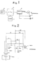
- Fig. 1 is a block diagram of the present invention, Fig. 2 is a schematic diagram, Fig. 3 is a flowchart illustrating an example of operation, and Fig. 4 is an external view of a horizontal articulated-type robot.
- An embodiment of the invention will now be described in detail with reference to the drawings. Fig.l is a schematic block diagram of the invention, in which a represents an input unit, b a CPU (central processing unit), and c a sensor provided on a robot hand for sensing that the robot hand has gripped a workpiece. For example, a weight sensor provided between the robot hand and wrist can be used as the sensor.
- Further, d denotes a servocontrol circuit, e a servomotor for drive along each axis of the robot, f a pulse coder for detecting the rotational angle of the servomotor, and g a tachogenerator for detecting the rotational speed of the servomotor.
- A method of commanding torque for the servomotor e by means of the robot control apparatus of the invention will now be described. The horizontal articulated-type robot shown in Fig. 4 can be expressed by a simplified diagram, as shown in Fig. 2. In the diagram, we have the following:
- ℓ1: length of first arm
- ℓ2: length of second arm
- ℓ2': length from
rotational axis 82 to hand (where we let ℓ2 = ℓ2' for simplicity) - mli, m2j: i-th and j-th weights obtained by dividing the weights of the arms of the respective axes by k, n, respectively
- ℓ1i, ℓ2j: lengths from the rotational centers of the axes to weight dividing points
- Considering the weight of a workpiece as being the weight m2n of an n-th material point of the second arm, drive torque T1 of a first axis θ1 is expressed by the following motion equation:

- The coefficients A, B, C and D of each of the non-linear terms represent the inertia corresponding to workpiece weight and arm position.
- When a horizontal articulated-type robot of this kind is used on a factory assembly line or the like, the operator inputs the weights m2n of various workpieces to the CPU b in advance by means of the input a. On the basis of the weight of each workpiece, the CPU b determines the coefficients A, B, C and D of the non-linear terms, which are dependent solely upon the position of the manipulator, in the abovementioned torque computation equation, and stores these coefficients as inertia terms corresponding to workpiece weight and arm position.
- Next, when the robot is operated to grip a workpiece, the sensor c sends a signal, which is indicative of the fact that the workpiece has been gripped, to the CPU b. In accordance with this signal sent by the sensor c and a signal indicative of manipulator position obtained from the pulse coder f, the CPU b reads out the corresponding inertia term and sends a control signal, which applies drive torque compensation to the servomotor e by feed-forward, to the servo-control circuit d.
- In the robot operation for gripping a workpiece, the robot control apparatus checks the control program of the robot and on the basis of this is capable of discriminating the type of workpiece about to be gripped or the type of workpiece being gripped.
- Fig. 3 is a flowchart illustrating an example of a processing operation performed by the above-described robot control apparatus.
- In order to apply a torque command to the first axis, T1 must be computed from the torque computation equation. However, in an ordinary robot motion equation, the rate of change in arm position may be assumed to be smaller than the rate of change in velocity or acceleration. Therefore, the position of the second axis, namely the rotational angle θ2, is obtained (step a). On the basis of this angle, the corresponding sine and cosine values are calculated from a function table or the like (step b). The inertia terms corresponding to the weight of the workpiece are then calculated (step c). Next, the velocity and acceleration θ1, θ1 along the firxt axis and the velocity and acceleration, θ2, θ2 along the second axis are obtained (step d). The torque T1 is calculated from the inertia values calculated and stored at step c (step e). The torque command is applied to the first axis (step f). This calculation cycle (steps d - f) is repeated n times (step g), during which identical interia values are taken as a reference. The program subsequently returns to step a. Letting B represent the calculation time at step (e), the flow of Fig. 3 will be repeated at a period A (>nB).
- It should be noted that it is unnecessary to fix the inertia term computation period A to n times the torque calculation period B, as is done in the above-described embodiment. For example, it will suffice to set the inertia term computation period to a large value with respect to the drive torque computation period in accordance with the motion of the robot hand. The present invention is not limited to the foregoing embodiment and can be modified in various ways within the gist of the invention without departing from the scope of the claims thereof.
- Thus, in accordance with the invention as described above, a rate of change in position is smaller than a rate of change in velocity or acceleration when torque is calculated using a robot motion equation. The inertia term calculation period A therefore can be set to be longer than the torque calculation period B, and the time required for torque calculation can be shortened. As a result, a highly precise torque command can be formed without interfering with other processing such as for current control. The invention is convenient in that processing for torque control and current control can be performed simultaneously.
- Though the present invention relates to a horizontal articulated-type robot, the invention can also be applied to industrial robots of polar coordinate-type as well as other forms of industrial robots.
Claims (3)
Applications Claiming Priority (2)
| Application Number | Priority Date | Filing Date | Title |
|---|---|---|---|
| JP61153739A JPH071463B2 (en) | 1986-06-30 | 1986-06-30 | Robot controller |
| JP153739/86 | 1986-06-30 |
Publications (3)
| Publication Number | Publication Date |
|---|---|
| EP0271590A1 true EP0271590A1 (en) | 1988-06-22 |
| EP0271590A4 EP0271590A4 (en) | 1990-11-28 |
| EP0271590B1 EP0271590B1 (en) | 1992-11-11 |
Family
ID=15569043
Family Applications (1)
| Application Number | Title | Priority Date | Filing Date |
|---|---|---|---|
| EP87904141A Expired - Lifetime EP0271590B1 (en) | 1986-06-30 | 1987-06-30 | Robot control apparatus |
Country Status (5)
| Country | Link |
|---|---|
| US (1) | US4908559A (en) |
| EP (1) | EP0271590B1 (en) |
| JP (1) | JPH071463B2 (en) |
| DE (1) | DE3782625T2 (en) |
| WO (1) | WO1988000369A1 (en) |
Cited By (1)
| Publication number | Priority date | Publication date | Assignee | Title |
|---|---|---|---|---|
| DE3839030A1 (en) * | 1988-11-18 | 1990-05-23 | Uwe Dipl Ing Gerstmann | Method for the improvement of the absolute positioning accuracy of positioning drives driven with at least one gear linkage, especially of robots, as well as positioning drive, especially robot, having a device for carrying out the method |
Families Citing this family (10)
| Publication number | Priority date | Publication date | Assignee | Title |
|---|---|---|---|---|
| JPH04310384A (en) * | 1991-04-09 | 1992-11-02 | Toyota Motor Corp | Double-arm robot |
| JPH01230107A (en) * | 1988-03-10 | 1989-09-13 | Fanuc Ltd | Method for detecting collision of body to be driven by servomotor |
| JPH07117858B2 (en) * | 1989-01-20 | 1995-12-18 | 株式会社日立製作所 | Robot motion control method |
| JPH02198783A (en) * | 1989-01-23 | 1990-08-07 | Fanuc Ltd | Correction method for positioning industrial robot |
| EP0430453B1 (en) * | 1989-11-30 | 1997-01-02 | Hewlett-Packard Company | Error recovery in a cartridge handling system |
| US5331264A (en) * | 1993-04-15 | 1994-07-19 | Fanuc Robotics North America, Inc. | Method and device for generating an input command for a motion control system |
| IT1266351B1 (en) * | 1993-05-17 | 1996-12-27 | Weber Srl | ELECTRONIC INJECTION TIME CALCULATION SYSTEM. |
| CN105643627A (en) * | 2014-11-12 | 2016-06-08 | 沈阳新松机器人自动化股份有限公司 | Gain adjustment device and method for robot motion control |
| JP6877729B2 (en) * | 2016-11-10 | 2021-05-26 | 中村留精密工業株式会社 | Parameter adjustment system for servo motor control device in machine tools |
| RU2653065C1 (en) * | 2017-01-31 | 2018-05-07 | федеральное государственное бюджетное образовательное учреждение высшего образования "Национальный исследовательский университет "МЭИ" (ФГБОУ ВО "НИУ "МЭИ") | Electric drive actuator unit |
Citations (2)
| Publication number | Priority date | Publication date | Assignee | Title |
|---|---|---|---|---|
| JPS603714A (en) * | 1983-06-22 | 1985-01-10 | Hitachi Ltd | Controlling method of robot |
| EP0128355B1 (en) * | 1983-06-13 | 1987-08-19 | Allied Corporation | Dynamic control for manipulator |
Family Cites Families (12)
| Publication number | Priority date | Publication date | Assignee | Title |
|---|---|---|---|---|
| US4156835A (en) * | 1974-05-29 | 1979-05-29 | Massachusetts Institute Of Technology | Servo-controlled mobility device |
| US4278920A (en) * | 1976-07-26 | 1981-07-14 | The Bendix Corporation | Method and apparatus for generating position or path control programs using force feedback |
| US4266905A (en) * | 1979-04-20 | 1981-05-12 | Board Of Regents For Education Of The State Of Rhode Island | Apparatus for acquiring workpieces from a storage bin or the like |
| JPS57151604U (en) * | 1981-03-16 | 1982-09-22 | ||
| JPS58143985A (en) * | 1982-02-20 | 1983-08-26 | 日本電信電話株式会社 | Control system of multiple freedom-degree kinetic mechanism |
| FR2527967B1 (en) * | 1982-06-07 | 1985-07-19 | Merlin Gerin | PERFECTED INDUSTRIAL ROBOT DRIVED BY A PROGRAMMABLE PLC |
| JPS58223583A (en) * | 1982-06-21 | 1983-12-26 | 三菱電機株式会社 | Control apparatus of industrial robot |
| JPS59191608A (en) * | 1983-04-11 | 1984-10-30 | ロツクウエル・インタ−ナシヨナル・コ−ポレ−シヨン | Improvement in processing through put speed |
| JPS6077210A (en) * | 1983-10-05 | 1985-05-01 | Nippon Telegr & Teleph Corp <Ntt> | Controlling method of spatial kinetic mechanism |
| JPS6327904A (en) * | 1986-07-22 | 1988-02-05 | Hitachi Ltd | Position correcting control system for servo mechanism device |
| US4774445A (en) * | 1986-11-20 | 1988-09-27 | Unimation, Inc. | Multiaxis robot control having capability for executing timed moves |
| US4792715A (en) * | 1987-11-16 | 1988-12-20 | Barsky Michael F | Robot gripper control system using PVDF piezoelectric sensors |
-
1986
- 1986-06-30 JP JP61153739A patent/JPH071463B2/en not_active Expired - Lifetime
-
1987
- 1987-06-30 DE DE8787904141T patent/DE3782625T2/en not_active Expired - Fee Related
- 1987-06-30 WO PCT/JP1987/000450 patent/WO1988000369A1/en active IP Right Grant
- 1987-06-30 EP EP87904141A patent/EP0271590B1/en not_active Expired - Lifetime
- 1987-06-30 US US07/157,506 patent/US4908559A/en not_active Expired - Fee Related
Patent Citations (2)
| Publication number | Priority date | Publication date | Assignee | Title |
|---|---|---|---|---|
| EP0128355B1 (en) * | 1983-06-13 | 1987-08-19 | Allied Corporation | Dynamic control for manipulator |
| JPS603714A (en) * | 1983-06-22 | 1985-01-10 | Hitachi Ltd | Controlling method of robot |
Non-Patent Citations (1)
| Title |
|---|
| See also references of WO8800369A1 * |
Cited By (1)
| Publication number | Priority date | Publication date | Assignee | Title |
|---|---|---|---|---|
| DE3839030A1 (en) * | 1988-11-18 | 1990-05-23 | Uwe Dipl Ing Gerstmann | Method for the improvement of the absolute positioning accuracy of positioning drives driven with at least one gear linkage, especially of robots, as well as positioning drive, especially robot, having a device for carrying out the method |
Also Published As
| Publication number | Publication date |
|---|---|
| EP0271590A4 (en) | 1990-11-28 |
| WO1988000369A1 (en) | 1988-01-14 |
| JPH071463B2 (en) | 1995-01-11 |
| JPS638913A (en) | 1988-01-14 |
| EP0271590B1 (en) | 1992-11-11 |
| US4908559A (en) | 1990-03-13 |
| DE3782625D1 (en) | 1992-12-17 |
| DE3782625T2 (en) | 1993-03-25 |
Similar Documents
| Publication | Publication Date | Title |
|---|---|---|
| EP0086950B1 (en) | Method of controlling an industrial robot | |
| US4621332A (en) | Method and apparatus for controlling a robot utilizing force, position, velocity, spring constant, mass coefficient, and viscosity coefficient | |
| CN100454198C (en) | Controller | |
| Ikeura et al. | Variable impedance control of a robot for cooperation with a human | |
| EP0130570B1 (en) | Method and apparatus for controlling a robot hand along a predetermined path | |
| US4433382A (en) | Apparatus for automatically adjusting the programmed location of a robot arm | |
| US6222338B1 (en) | Method and apparatus for the direct teaching of automatic machines | |
| US4542471A (en) | Robot control system for presetting limit values corresponding to limits of deviation | |
| EP0260326A1 (en) | Robot controller | |
| EP0271590B1 (en) | Robot control apparatus | |
| US5742138A (en) | Control method for servo system with adjustable softness in rectangular coordinate system | |
| EP0240570A1 (en) | Acceleration and deceleration control system for horizontal-joint robots | |
| US5191272A (en) | Method of adjusting gain for motor control | |
| Yanai et al. | Feedback control for wire-suspended mechanism with exact linearization | |
| EP0328650A1 (en) | Method and apparatus for directly teaching horizontal arm-type multi-articulated robot | |
| JPH05111889A (en) | Control of variable control type robot | |
| US5751130A (en) | Time constant setting method for a track program of a robot | |
| EP0076331A1 (en) | Robot controlling device | |
| JPS638912A (en) | Control system for robot | |
| KR20040034167A (en) | The method of control- ling straight-line movement of vertical multi-joint six-axis manipulator | |
| JP3350687B2 (en) | Robot control method and robot control device | |
| Kikuchi et al. | Heavy parts assembly by coordinative control of robot and balancing manipulator | |
| KR0157634B1 (en) | Adaptation control method of robot | |
| KR100187214B1 (en) | A motor speed control apparatus and method | |
| JPS62295893A (en) | Control system of robot |
Legal Events
| Date | Code | Title | Description |
|---|---|---|---|
| PUAI | Public reference made under article 153(3) epc to a published international application that has entered the european phase |
Free format text: ORIGINAL CODE: 0009012 |
|
| 17P | Request for examination filed |
Effective date: 19871215 |
|
| AK | Designated contracting states |
Kind code of ref document: A1 Designated state(s): DE FR GB |
|
| A4 | Supplementary search report drawn up and despatched |
Effective date: 19901011 |
|
| AK | Designated contracting states |
Kind code of ref document: A4 Designated state(s): DE FR GB |
|
| RHK1 | Main classification (correction) |
Ipc: B25J 9/18 |
|
| 17Q | First examination report despatched |
Effective date: 19920108 |
|
| GRAA | (expected) grant |
Free format text: ORIGINAL CODE: 0009210 |
|
| STAA | Information on the status of an ep patent application or granted ep patent |
Free format text: STATUS: THE PATENT HAS BEEN GRANTED |
|
| AK | Designated contracting states |
Kind code of ref document: B1 Designated state(s): DE FR GB |
|
| REF | Corresponds to: |
Ref document number: 3782625 Country of ref document: DE Date of ref document: 19921217 |
|
| ET | Fr: translation filed | ||
| PLBE | No opposition filed within time limit |
Free format text: ORIGINAL CODE: 0009261 |
|
| 26N | No opposition filed | ||
| PGFP | Annual fee paid to national office [announced via postgrant information from national office to epo] |
Ref country code: GB Payment date: 19931206 Year of fee payment: 7 |
|
| PGFP | Annual fee paid to national office [announced via postgrant information from national office to epo] |
Ref country code: FR Payment date: 19931217 Year of fee payment: 7 |
|
| PG25 | Lapsed in a contracting state [announced via postgrant information from national office to epo] |
Ref country code: GB Effective date: 19940630 |
|
| PG25 | Lapsed in a contracting state [announced via postgrant information from national office to epo] |
Ref country code: FR Effective date: 19950228 |
|
| GBPC | Gb: european patent ceased through non-payment of renewal fee |
Effective date: 19940630 |
|
| REG | Reference to a national code |
Ref country code: FR Ref legal event code: ST |
|
| PGFP | Annual fee paid to national office [announced via postgrant information from national office to epo] |
Ref country code: DE Payment date: 20000626 Year of fee payment: 14 |
|
| PG25 | Lapsed in a contracting state [announced via postgrant information from national office to epo] |
Ref country code: DE Free format text: LAPSE BECAUSE OF NON-PAYMENT OF DUE FEES Effective date: 20020403 |