EP0271450A2 - Gabelkopf für den Biegebereich einer Rohrbiegemaschine, der mit dem Steuerteil verbindbar ist und Arme zum Tragen der genuteten Widerlager für das zu biegende Rohr aufweist - Google Patents
Gabelkopf für den Biegebereich einer Rohrbiegemaschine, der mit dem Steuerteil verbindbar ist und Arme zum Tragen der genuteten Widerlager für das zu biegende Rohr aufweist Download PDFInfo
- Publication number
- EP0271450A2 EP0271450A2 EP87830335A EP87830335A EP0271450A2 EP 0271450 A2 EP0271450 A2 EP 0271450A2 EP 87830335 A EP87830335 A EP 87830335A EP 87830335 A EP87830335 A EP 87830335A EP 0271450 A2 EP0271450 A2 EP 0271450A2
- Authority
- EP
- European Patent Office
- Prior art keywords
- pipe
- bending
- arms
- fork member
- base
- Prior art date
- Legal status (The legal status is an assumption and is not a legal conclusion. Google has not performed a legal analysis and makes no representation as to the accuracy of the status listed.)
- Granted
Links
Images
Classifications
-
- B—PERFORMING OPERATIONS; TRANSPORTING
- B21—MECHANICAL METAL-WORKING WITHOUT ESSENTIALLY REMOVING MATERIAL; PUNCHING METAL
- B21D—WORKING OR PROCESSING OF SHEET METAL OR METAL TUBES, RODS OR PROFILES WITHOUT ESSENTIALLY REMOVING MATERIAL; PUNCHING METAL
- B21D7/00—Bending rods, profiles, or tubes
- B21D7/06—Bending rods, profiles, or tubes in press brakes or between rams and anvils or abutments; Pliers with forming dies
- B21D7/063—Pliers with forming dies
Definitions
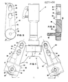
- the object of the present industrial model is a fork member as a part of the bending section of a pipe-bending apparatus, generally of the portable manually-controlled hydraulic type, which may be connected easily to the control section through the free end of the body of the apparatus along the axis of the piston of this latter which operates the bending member- or matrix - and is provided with two arms to support the concave grooved abutment members of the pipe to be bent.
- the substantial innovating feature of such a fork member is the constitution of same as a flat base comprising: an integral component element to be connected with the free end of the main body of the apparatus in such a manner that it may rotate freely together with this latter about its longitudinal axis; a pair of pins protruding from the flat surfaces of the base and symmetrically spaced from a longitudinal plane perpendicular to that base, along the axis of the pipe-bending apparatus; a set of three slots provided on the flat surfaces of both shanks of the fork member according to radial directions which are specular to each other in said two shanks when referred to said plane, each set of slots being departing from the pin of respective shank; a pair of arms as carriers of abutment members of the pipe to be bent, each arm being solidly and quickly connectible to the respective base pin according to the selected slot direction.
- the main scope of the industrial model is to create, for the bending section of such a pipe-bending apparatus, a form member which allows: a notable reduction of the pipe-bending members with respect to those which are usually necessary to bend pipes the diameters of which are comprised in a selected range considered suitable for the pipe-bending apparatus to be used; the quick and easy positioning of the pair of arms on said base along the specular directions defined by the corresponding slots of the two sets of slots provided on the form member shanks; limitation of the fork section components to such fork member and the auxiliary arms to be mounted thereon, these arms being in turn used to mount thereon the pipe abutment members opposite to the bending member, or matrix, when a bending operation is to carry out, so that the equipment weight of the bending apparatus will be reduced and the carriage of same will be easier.
- base 11 of this fork member comprises a flat piece with two parted wide legs 12, 13 and a part 14 protruding upwards.
- the base which sets up one of the innova ting features of this industrial model, has a specular configuration referred to a vertical plan perpendicular to the drawing sheet, along the longitudinal axis of member 15 to be connected to neck C of a pipe-bending apparatus A of the cited type (see Fig.1).
- the end portion of stem 8 which is protruding downwards is usually used to mount thereon a bending member (not shown).
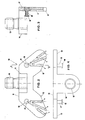
- a pair of pins 17, 19 are protruding from the front surface of base 11 with respective heads 16, 18 of larger diameter. These pins are positioned symmetrically when referred to that plane perpedicular to such front surface, along the axis of connecting member 15 of apparatus A. As shown, from the axis of each pin 17, 19 three slots a , b and c are provided to define respective radial directions specularly predetermined and form the possible seat of rib 26 (see Figs.5, 6) protruding from arm 20 because of the like shape of slot and rib, preferably at right angles. As it will be recalled later, each arm 20 may thus be mounted on respective fork leg and solidly connected to this latter.
- each arm 20 on base 11 to define the position of respective abutment member 31 of the pipe to be bent, as evidences in Fig.1, is due to the appropriate shape and suitable position of elongated openings 22 and 24 provided in each arm 20 along the longitudinal axis of this latter.
- each elongated opening has a partial portion sufficiently wide to allow the free passage therethrough of the head 16, 18 of pins 17, 19 which are protruding from the flat surface of base 11.
- the diameter of such heads is larger than the body of the pins, while a remainder arcuated portion has a smaller diameter correspon ding to the pin body and a smaller height which forms a low step 23 (or 25). Because of this particular shape and dimensions the operator may pass a pin head through the wider portion 22, 24 of the opening and place arm 20 along the selected direction (corresponding to slot a , b and c ) and seat rib 26 therein, in order that arm 20 may be slided up to lean the pin head against step 23 (or 25).
- arm 20 is suitably connected to a corresponding leg 12 or 13 of fork member 10 in consequence of its solid leaning on the flat surface of this latter.
- An appropriate thin washer preferably of a flat splitted spring type with ondulations along the annular surface of same, may better aid to obtain satisfying conditions of friction between the concerned contact areas of flat surface of base 11 and arm 20.
- each arm 20 was supposed with rib 26 inserted within respective slot b of fork member leg 12 and leg 13 in accordancce with this new type of fork member 10. It was also supposed that arms 20 are mounted on pins 17 and 19, respectively, of the base 11 by passing these latter through the opening of each arm indicated by the reference numeral 22.
- the center distance between the pins indicated by the character L in Fig.1 constitutes one of the six possible center-to-center distance which may be realized between pins 28 used to mount the abutment members 30 of a pipe to be bent.
- the pipe abutment members are of the roto-translating type, already evidenced in prior patents of the Applicant.
- slots a , b and c are specularly provided in the two fork member legs 12, 13 of base 11 in accordance with the innovating features of this model; fork member 10 allows, through these slots, the arrangement of the two arms along the directions of the respective slots a , or b or c ; each arm is provided with two elongated openings 22, 24 along the longitudinal axis of same, it will be understood that an easy and quick realization of a total number of six (3x2) center distances is possible between the pins 28,28 of the abutment members 30,30, respectively of the pipe to be bent.
- a first comparison limited to the number of fork members to be used by the operator to bend pipes whose total range of diameter is from 4 to 22 mm, evidences very clearly that through a single fork member 10 in accordance with the present industrial model is possible to have a number of center distances greater than through said fork members 1), 2) and 3), useful intermediate center distances being also possible to carry out satisfactory bending operations.
- a second comparison concerns the necessary number of bending members to be used with cited fork members of prior art and referred to the diameter ranges 1), 2) and 3).
- following equipment of bending members is required to carry out satisfactory bending operations: for a fork member listed in 1) : 6 bending members for a fork member listed in 2) : 8 bending members for a fork member listed in 3) : 11 bending members
- the equipment to bend pipes whose diameter range is from 4 to 22 comprises then a total of 25 bending members. It is to recall what said above in relation to some pipe diameters listed in more than one of items 1), 2) and 3) as regards the approximate center distances between the pipe abutment members of a corresponding fork member, and deduce that the use of that bending member which is considered more suitable to realize a good bending operation is obviously advisable.
- the equipment will require a very lower number of bending members, namely: for diameter range 1) : 6 bending members for diameter range 2) : 4 bending members for diameter range 3) : 2 bending members i.e. a total of 12 bending members only for same pipe-bending apparatus to the bottom end of which a single fork member 10 is to be connected, the legs 12, 13 of such fork member 10 being provided with respective arms 20 suitably mounted on base 11.
- Fig.2 the slots indicated by characters a , b , c on legs 12 and 13 of the flat base 11 must be considered as the seats of arms 20 and particularly the seats of respective ribs 26.
- arms 20 are mounted along the specular slots b of the legs and create then a center distance L between pins 28 of the pipe abutment members 30 when mounted on pins 17, 19, as shown .
Landscapes
- Engineering & Computer Science (AREA)
- Mechanical Engineering (AREA)
- Bending Of Plates, Rods, And Pipes (AREA)
- Fluid-Damping Devices (AREA)
- Table Equipment (AREA)
- Steering Devices For Bicycles And Motorcycles (AREA)
- Mutual Connection Of Rods And Tubes (AREA)
Priority Applications (1)
| Application Number | Priority Date | Filing Date | Title |
|---|---|---|---|
| AT87830335T ATE65722T1 (de) | 1986-11-28 | 1987-09-22 | Gabelkopf fuer den biegebereich einer rohrbiegemaschine, der mit dem steuerteil verbindbar ist und arme zum tragen der genuteten widerlager fuer das zu biegende rohr aufweist. |
Applications Claiming Priority (2)
| Application Number | Priority Date | Filing Date | Title |
|---|---|---|---|
| IT3628186U | 1986-11-28 | ||
| IT8636281U IT208450Z2 (it) | 1986-11-28 | 1986-11-28 | Forcella della sezione curvatura di un apparecchio curvatubi con la sezione comando annettibile provvista di bracci per i supporti a gola del tubo che ha curvato |
Publications (3)
| Publication Number | Publication Date |
|---|---|
| EP0271450A2 true EP0271450A2 (de) | 1988-06-15 |
| EP0271450A3 EP0271450A3 (en) | 1988-09-07 |
| EP0271450B1 EP0271450B1 (de) | 1991-07-31 |
Family
ID=11245529
Family Applications (1)
| Application Number | Title | Priority Date | Filing Date |
|---|---|---|---|
| EP87830335A Expired - Lifetime EP0271450B1 (de) | 1986-11-28 | 1987-09-22 | Gabelkopf für den Biegebereich einer Rohrbiegemaschine, der mit dem Steuerteil verbindbar ist und Arme zum Tragen der genuteten Widerlager für das zu biegende Rohr aufweist |
Country Status (9)
| Country | Link |
|---|---|
| US (1) | US4811589A (de) |
| EP (1) | EP0271450B1 (de) |
| JP (1) | JPH0340409Y2 (de) |
| KR (1) | KR900010324Y1 (de) |
| AT (1) | ATE65722T1 (de) |
| DE (1) | DE3771854D1 (de) |
| ES (1) | ES2025208B3 (de) |
| GR (1) | GR3003000T3 (de) |
| IT (1) | IT208450Z2 (de) |
Cited By (1)
| Publication number | Priority date | Publication date | Assignee | Title |
|---|---|---|---|---|
| CN112958664A (zh) * | 2021-02-02 | 2021-06-15 | 中国十七冶集团有限公司 | 一种便于镀锌钢管自动弯曲的工具及使用方法 |
Families Citing this family (1)
| Publication number | Priority date | Publication date | Assignee | Title |
|---|---|---|---|---|
| IT1261753B (it) * | 1993-01-29 | 1996-06-03 | Cml Costr Mecc Liri Srl | Giunto tra l'organo di comando e azionamento e la testa di lavoro di una macchina curvatubi portatile. |
Family Cites Families (11)
| Publication number | Priority date | Publication date | Assignee | Title |
|---|---|---|---|---|
| GB642044A (en) * | 1947-01-16 | 1950-08-23 | Tal Bender Inc | Pipe bending apparatus |
| FR1025172A (fr) * | 1950-09-26 | 1953-04-13 | Machine à cintrer multiple | |
| SU421403A1 (ru) * | 1972-07-05 | 1974-03-30 | коммунального хоз йства К. Д. Памфилова | ПЕРЕНОСНОЙ ТРУБОГИБС-г:: |
| DE2613621A1 (de) * | 1975-04-03 | 1976-10-14 | Mec Fratelli Caporusso Piedimo | Vorrichtung zum biegen von rohren |
| US3918286A (en) * | 1975-10-17 | 1975-11-11 | Willard Whitehead | U-Bolt bending machine |
| US4141235A (en) * | 1976-09-18 | 1979-02-27 | Masamitsu Ishihara | Hydraulic bending machine |
| DE2824074A1 (de) * | 1977-09-08 | 1979-03-22 | Belotti Flli | Geraet zum biegen und/oder kruemmen von rohren oder stangen mit dazugehoerender motorpumpengruppe |
| GB2099734A (en) * | 1981-05-22 | 1982-12-15 | Forem Contractors Ltd | Bending apparatus and method |
| SU1261731A1 (ru) * | 1982-06-01 | 1986-10-07 | Всесоюзный Научно-Исследовательский,Проектно-Конструкторский И Технологический Институт Трансформаторостроения | Устройство дл гибки преимущественно обмоточного провода на ребро |
| US4462243A (en) * | 1982-09-20 | 1984-07-31 | J. A. Richards Company | Tool support for machines |
| US4638665A (en) * | 1985-10-03 | 1987-01-27 | Full Vision, Inc. | Tube bender |
-
1986
- 1986-11-28 IT IT8636281U patent/IT208450Z2/it active
-
1987
- 1987-09-22 AT AT87830335T patent/ATE65722T1/de not_active IP Right Cessation
- 1987-09-22 ES ES87830335T patent/ES2025208B3/es not_active Expired - Lifetime
- 1987-09-22 DE DE87830335T patent/DE3771854D1/de not_active Expired - Fee Related
- 1987-09-22 EP EP87830335A patent/EP0271450B1/de not_active Expired - Lifetime
- 1987-11-10 JP JP1987171924U patent/JPH0340409Y2/ja not_active Expired
- 1987-11-12 US US07/119,173 patent/US4811589A/en not_active Expired - Lifetime
- 1987-11-25 KR KR2019870020454U patent/KR900010324Y1/ko not_active Expired
-
1991
- 1991-10-24 GR GR91401620T patent/GR3003000T3/el unknown
Cited By (2)
| Publication number | Priority date | Publication date | Assignee | Title |
|---|---|---|---|---|
| CN112958664A (zh) * | 2021-02-02 | 2021-06-15 | 中国十七冶集团有限公司 | 一种便于镀锌钢管自动弯曲的工具及使用方法 |
| CN112958664B (zh) * | 2021-02-02 | 2022-05-13 | 中国十七冶集团有限公司 | 一种便于镀锌钢管自动弯曲的工具及使用方法 |
Also Published As
| Publication number | Publication date |
|---|---|
| IT208450Z2 (it) | 1988-05-28 |
| EP0271450A3 (en) | 1988-09-07 |
| JPH0340409Y2 (de) | 1991-08-26 |
| GR3003000T3 (en) | 1993-01-25 |
| KR880009531U (ko) | 1988-07-23 |
| ES2025208B3 (es) | 1992-03-16 |
| DE3771854D1 (en) | 1991-09-05 |
| EP0271450B1 (de) | 1991-07-31 |
| JPS6390520U (de) | 1988-06-11 |
| KR900010324Y1 (ko) | 1990-11-10 |
| ATE65722T1 (de) | 1991-08-15 |
| US4811589A (en) | 1989-03-14 |
| IT8636281V0 (it) | 1986-11-28 |
Similar Documents
| Publication | Publication Date | Title |
|---|---|---|
| EP0862385B1 (de) | Schwenkbare klammer | |
| EP0914988A3 (de) | Haltearm für einen Kraftfahrzeug-Aussenspiegel mit integriertem Schwenkgelenk | |
| US4134578A (en) | Clamp | |
| US4942662A (en) | Adjustable arcuate razor head | |
| JPH02246802A (ja) | 車輪調整用リムクランプのつめ | |
| US4813260A (en) | Multipurpose tube working tool | |
| US4140306A (en) | Fixture for mounting an article to be worked on | |
| US4868946A (en) | Adjustable roller frame | |
| EP0271450A2 (de) | Gabelkopf für den Biegebereich einer Rohrbiegemaschine, der mit dem Steuerteil verbindbar ist und Arme zum Tragen der genuteten Widerlager für das zu biegende Rohr aufweist | |
| US6171011B1 (en) | Structure of pivot joint | |
| US6327944B1 (en) | Structure of pliers with variable nose | |
| US5107577A (en) | Tool mounting fixture | |
| CN214921632U (zh) | 焊接治具、焊接设备 | |
| US10029351B2 (en) | Clamping tool | |
| GB2098936A (en) | Tyre changers | |
| US5050422A (en) | Bending apparatus for bending a marginal flange on a workpiece | |
| US6186377B1 (en) | Shirt pressing machine for long or short sleeve shirts | |
| CN222493876U (zh) | 夹持件和产品的固定装置 | |
| EP0371162B1 (de) | Verstellbare Nietzange | |
| EP4112386A1 (de) | Fahrradquerstangenadapter | |
| US4265436A (en) | Workpiece support device and auxiliary support body arrangement | |
| CN215903098U (zh) | 一种管状件夹持装置 | |
| GB2354733A (en) | Mitre saw | |
| US5775660A (en) | Clamp assembly | |
| CN219432245U (zh) | 缺口铆卡 |
Legal Events
| Date | Code | Title | Description |
|---|---|---|---|
| PUAI | Public reference made under article 153(3) epc to a published international application that has entered the european phase |
Free format text: ORIGINAL CODE: 0009012 |
|
| AK | Designated contracting states |
Kind code of ref document: A2 Designated state(s): AT BE CH DE ES FR GB GR LI LU NL SE |
|
| PUAL | Search report despatched |
Free format text: ORIGINAL CODE: 0009013 |
|
| AK | Designated contracting states |
Kind code of ref document: A3 Designated state(s): AT BE CH DE ES FR GB GR LI LU NL SE |
|
| 17P | Request for examination filed |
Effective date: 19881222 |
|
| 17Q | First examination report despatched |
Effective date: 19891124 |
|
| GRAA | (expected) grant |
Free format text: ORIGINAL CODE: 0009210 |
|
| AK | Designated contracting states |
Kind code of ref document: B1 Designated state(s): AT BE CH DE ES FR GB GR LI LU NL SE |
|
| PG25 | Lapsed in a contracting state [announced via postgrant information from national office to epo] |
Ref country code: LI Effective date: 19910731 Ref country code: CH Effective date: 19910731 |
|
| REF | Corresponds to: |
Ref document number: 65722 Country of ref document: AT Date of ref document: 19910815 Kind code of ref document: T |
|
| REF | Corresponds to: |
Ref document number: 3771854 Country of ref document: DE Date of ref document: 19910905 |
|
| PG25 | Lapsed in a contracting state [announced via postgrant information from national office to epo] |
Ref country code: ES Free format text: LAPSE BECAUSE OF THE APPLICANT RENOUNCES Effective date: 19910923 |
|
| REG | Reference to a national code |
Ref country code: CH Ref legal event code: PL |
|
| ET | Fr: translation filed | ||
| REG | Reference to a national code |
Ref country code: ES Ref legal event code: FG2A Ref document number: 2025208 Country of ref document: ES Kind code of ref document: B3 |
|
| PLBE | No opposition filed within time limit |
Free format text: ORIGINAL CODE: 0009261 |
|
| STAA | Information on the status of an ep patent application or granted ep patent |
Free format text: STATUS: NO OPPOSITION FILED WITHIN TIME LIMIT |
|
| 26N | No opposition filed | ||
| REG | Reference to a national code |
Ref country code: GR Ref legal event code: FG4A Free format text: 3003000 |
|
| EPTA | Lu: last paid annual fee | ||
| EAL | Se: european patent in force in sweden |
Ref document number: 87830335.3 |
|
| REG | Reference to a national code |
Ref country code: ES Ref legal event code: FD2A Effective date: 19991007 |
|
| PGFP | Annual fee paid to national office [announced via postgrant information from national office to epo] |
Ref country code: SE Payment date: 20000810 Year of fee payment: 14 |
|
| PGFP | Annual fee paid to national office [announced via postgrant information from national office to epo] |
Ref country code: AT Payment date: 20000926 Year of fee payment: 14 |
|
| PGFP | Annual fee paid to national office [announced via postgrant information from national office to epo] |
Ref country code: LU Payment date: 20000929 Year of fee payment: 14 |
|
| PGFP | Annual fee paid to national office [announced via postgrant information from national office to epo] |
Ref country code: NL Payment date: 20000930 Year of fee payment: 14 |
|
| PGFP | Annual fee paid to national office [announced via postgrant information from national office to epo] |
Ref country code: BE Payment date: 20001103 Year of fee payment: 14 |
|
| PG25 | Lapsed in a contracting state [announced via postgrant information from national office to epo] |
Ref country code: LU Free format text: LAPSE BECAUSE OF NON-PAYMENT OF DUE FEES Effective date: 20010922 Ref country code: AT Free format text: LAPSE BECAUSE OF NON-PAYMENT OF DUE FEES Effective date: 20010922 |
|
| PG25 | Lapsed in a contracting state [announced via postgrant information from national office to epo] |
Ref country code: SE Free format text: LAPSE BECAUSE OF NON-PAYMENT OF DUE FEES Effective date: 20010923 |
|
| PGFP | Annual fee paid to national office [announced via postgrant information from national office to epo] |
Ref country code: GR Payment date: 20010924 Year of fee payment: 15 |
|
| PG25 | Lapsed in a contracting state [announced via postgrant information from national office to epo] |
Ref country code: BE Free format text: LAPSE BECAUSE OF NON-PAYMENT OF DUE FEES Effective date: 20010930 |
|
| REG | Reference to a national code |
Ref country code: GB Ref legal event code: IF02 |
|
| BERE | Be: lapsed |
Owner name: COSTRUZIONI MECCANICHE LIRI S.R.L. CML Effective date: 20010930 |
|
| PG25 | Lapsed in a contracting state [announced via postgrant information from national office to epo] |
Ref country code: NL Free format text: LAPSE BECAUSE OF NON-PAYMENT OF DUE FEES Effective date: 20020401 |
|
| EUG | Se: european patent has lapsed |
Ref document number: 87830335.3 |
|
| NLV4 | Nl: lapsed or anulled due to non-payment of the annual fee |
Effective date: 20020401 |
|
| PGFP | Annual fee paid to national office [announced via postgrant information from national office to epo] |
Ref country code: GB Payment date: 20020912 Year of fee payment: 16 |
|
| PGFP | Annual fee paid to national office [announced via postgrant information from national office to epo] |
Ref country code: FR Payment date: 20020927 Year of fee payment: 16 |
|
| PGFP | Annual fee paid to national office [announced via postgrant information from national office to epo] |
Ref country code: DE Payment date: 20021126 Year of fee payment: 16 |
|
| PG25 | Lapsed in a contracting state [announced via postgrant information from national office to epo] |
Ref country code: GR Free format text: LAPSE BECAUSE OF NON-PAYMENT OF DUE FEES Effective date: 20030404 |
|
| NLV4 | Nl: lapsed or anulled due to non-payment of the annual fee |
Effective date: 20020401 |
|
| PG25 | Lapsed in a contracting state [announced via postgrant information from national office to epo] |
Ref country code: GB Free format text: LAPSE BECAUSE OF NON-PAYMENT OF DUE FEES Effective date: 20030922 |
|
| PG25 | Lapsed in a contracting state [announced via postgrant information from national office to epo] |
Ref country code: DE Free format text: LAPSE BECAUSE OF NON-PAYMENT OF DUE FEES Effective date: 20040401 |
|
| GBPC | Gb: european patent ceased through non-payment of renewal fee |
Effective date: 20030922 |
|
| PG25 | Lapsed in a contracting state [announced via postgrant information from national office to epo] |
Ref country code: FR Free format text: LAPSE BECAUSE OF NON-PAYMENT OF DUE FEES Effective date: 20040528 |
|
| REG | Reference to a national code |
Ref country code: FR Ref legal event code: ST |