EP0270766A2 - Mécanisme de commande hydraulique refroidi par un fluide pour le moulage par injection - Google Patents
Mécanisme de commande hydraulique refroidi par un fluide pour le moulage par injection Download PDFInfo
- Publication number
- EP0270766A2 EP0270766A2 EP87114679A EP87114679A EP0270766A2 EP 0270766 A2 EP0270766 A2 EP 0270766A2 EP 87114679 A EP87114679 A EP 87114679A EP 87114679 A EP87114679 A EP 87114679A EP 0270766 A2 EP0270766 A2 EP 0270766A2
- Authority
- EP
- European Patent Office
- Prior art keywords
- cylinder
- piston
- valve pin
- injection molding
- hydraulic fluid
- Prior art date
- Legal status (The legal status is an assumption and is not a legal conclusion. Google has not performed a legal analysis and makes no representation as to the accuracy of the status listed.)
- Granted
Links
- 239000012530 fluid Substances 0.000 title claims abstract description 35
- 238000001746 injection moulding Methods 0.000 title claims abstract description 21
- 230000007246 mechanism Effects 0.000 title claims abstract description 16
- 238000001816 cooling Methods 0.000 claims abstract description 23
- 239000000155 melt Substances 0.000 claims description 9
- 238000000465 moulding Methods 0.000 abstract description 4
- 229920005989 resin Polymers 0.000 abstract description 2
- 239000011347 resin Substances 0.000 abstract description 2
- 230000007257 malfunction Effects 0.000 abstract 1
- 238000007789 sealing Methods 0.000 description 6
- 238000010438 heat treatment Methods 0.000 description 5
- 238000004519 manufacturing process Methods 0.000 description 3
- 239000000463 material Substances 0.000 description 3
- 238000002347 injection Methods 0.000 description 2
- 239000007924 injection Substances 0.000 description 2
- 238000000034 method Methods 0.000 description 2
- 229910001220 stainless steel Inorganic materials 0.000 description 2
- 239000010935 stainless steel Substances 0.000 description 2
- 230000003068 static effect Effects 0.000 description 2
- XLYOFNOQVPJJNP-UHFFFAOYSA-N water Substances O XLYOFNOQVPJJNP-UHFFFAOYSA-N 0.000 description 2
- RYGMFSIKBFXOCR-UHFFFAOYSA-N Copper Chemical compound [Cu] RYGMFSIKBFXOCR-UHFFFAOYSA-N 0.000 description 1
- 229910000831 Steel Inorganic materials 0.000 description 1
- 229920004738 ULTEM® Polymers 0.000 description 1
- 238000005219 brazing Methods 0.000 description 1
- 229910052802 copper Inorganic materials 0.000 description 1
- 239000010949 copper Substances 0.000 description 1
- 238000000354 decomposition reaction Methods 0.000 description 1
- 238000005553 drilling Methods 0.000 description 1
- NBVXSUQYWXRMNV-UHFFFAOYSA-N fluoromethane Chemical compound FC NBVXSUQYWXRMNV-UHFFFAOYSA-N 0.000 description 1
- 239000011521 glass Substances 0.000 description 1
- 239000012943 hotmelt Substances 0.000 description 1
- 238000012986 modification Methods 0.000 description 1
- 230000004048 modification Effects 0.000 description 1
- 238000013021 overheating Methods 0.000 description 1
- 230000036316 preload Effects 0.000 description 1
- 239000010959 steel Substances 0.000 description 1
Images


Classifications
-
- B—PERFORMING OPERATIONS; TRANSPORTING
- B29—WORKING OF PLASTICS; WORKING OF SUBSTANCES IN A PLASTIC STATE IN GENERAL
- B29C—SHAPING OR JOINING OF PLASTICS; SHAPING OF MATERIAL IN A PLASTIC STATE, NOT OTHERWISE PROVIDED FOR; AFTER-TREATMENT OF THE SHAPED PRODUCTS, e.g. REPAIRING
- B29C45/00—Injection moulding, i.e. forcing the required volume of moulding material through a nozzle into a closed mould; Apparatus therefor
- B29C45/17—Component parts, details or accessories; Auxiliary operations
- B29C45/26—Moulds
- B29C45/27—Sprue channels ; Runner channels or runner nozzles
- B29C45/28—Closure devices therefor
- B29C45/2806—Closure devices therefor consisting of needle valve systems
- B29C45/281—Drive means therefor
Definitions
- This invention relates to injection molding and more particularly to fluid cooled hydraulic actuating mechanism for a multi-cavity gated injection molding system.
- the invention provides a valve gated injection molding system comprising a manifold extending between a mold back plate and a plurality of spaced heated nozzles, each nozzle being seated in a cavity plate with a central bore in alignment with a gate leading to a cavity, an elongated valve pin having a driven end and a tip end mounted in the central bore of each nozzle, the driven end of each valve pin being operatively connected to hydraulic valve pin actuating mechanism mounted on the mold back plate whereby the valve pin is reciprocated between a retracted open position and a closed position wherein the tip end of the valve pin is seated in the gate and a melt passage branching from a common inlet in the manifold to longitudinal bores extending in the manifold to convey melt around the valve pin through the central bore of each nozzle to the respective gate, the improvement wherein, the valve pin actuating mechanism compresses a piston which is seated in a cylinder and connected to the driven end of the valve pin, at least three
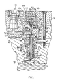
- FIG. 1 shows a portion of a multi-cavity valve gated injection molding system.
- a manifold 10 extends between a mold back plate 12 and a number of heated nozzles 14 seated in a cavity plate 16.
- Each nozzle 14 is fixed to the manifold 10 by bolts 18 which extend through the manifold and also fix a sealing and retaining bushing 20 to the other side of the manifold.
- the seating and retaining manifold 20 has a collar portion 22 which is seated in a well 24 in the manifold 10 and an outer flanged portion 26 which extends to contact the mold back plate 12 during operation.
- the bushing 20 is described in more details in the applicant's Canadian patent application serial number 520,519 entitled “Sealing and Retaining Bushing for Injection Molding” filed October 15, 1986.
- the sealing and retaining bushing has a central bore 28 aligned with a transverse bore 30 through the manifold 10 and a central bore 32 through the nozzle 14.
- the nozzle 14 is seated in the well 24 of the cavity plate with a location bushing portion 34 sitting on a shoulder 36. This locates the nozzle 12 with its central bore 32 in alignment with a gate 38 which extends through the cavity plate 16 to one of the cavities 40 formed between the cavity plate and a movable mold platen 42.
- the heated nozzles 14 or sprue bushings 14 are made as described in U.S. patent number 4,446,360 to Gellert entitled "Sprue Bushing Connector Assembly" which issued May 1, 1984.
- a helical heating element 44 is cast in a copper portion 46 between a stainless steel outer portion 48 and a stainless steel inner portion 50 which forms the central bore 32.
- An elongated valve pin 52 having a driven end 54 with an enlarged head 56 and a tip end 58 extends through the aligned central bore 28 of the bushing, the transverse bore 30 through the manifold 10 and the central bore 32 of the nozzle 14.
- the driven end 54 of the valve pin 52 is connected to actuating mechanism seated in the mold back plate 12 which reciprocates the valve pin 52 between a retracted open position and a closed position in which the tip end 58 is seated in the gate 38.
- the actuating mechanism includes a piston 60 which reciprocates in a cylinder 62.
- the valve pin 52 extends through the piston 60 and the enlarged head 56 is secured to it by a threaded plug.
- the piston 60 has an elongated neck portion 66 which protrudes out an opening 68 in the cylinder 62.
- a V-shaped high pressure seal 70 which is seated in the cylinder 62 extends around the neck portion 66 to prevent leakage of pressurized hydraulic fluid.
- the seal 70 is held in place by a washer 69 and a split resilient retaining or snap ring 71.
- the actuating mechanism is driven by hydraulic fluid as described in more detail below.
- a melt passage 72 extends through a heated sprue bushing 74 which receives pressurized melt from a molding machine (not shown) to the manifold 10 where it branches out through longitudinal bores 76.
- the sprue bushing 74 in this embodiment is made by the method described in Gellert's Canadian patent application serial number 496,645 entitled "Manufacturing Method for Selected Gate Configuration Injection Molding Nozzles" filed December 2, 1985.
- Each longitudinal bore 76 connects to an enlarged portion 78 of the transverse bore 30 through the manifold.
- the melt passage 72 extends through the enlarged portion 78 of the transverse bore 30 and through the central bore 32 through the nozzle around the valve pin 52 to the gate 38.
- a machined plug 80 is brazed into the manifold 10 to provide a smooth joint between them as described in the applicant's U.S. patent number 4,609,138 entitled “Method of Manufacturing Injection Molding Manifold with Plugs” which issued September 2, 1986.
- an insulative air space 86 is provided between each nozzle 14 and the surrounding cavity plate 16 by the locating bushing portion 34 seating on shoulder 36.
- another insulative air space 88 is provided between the hot manifold 10 and the cooled cavity plate 16 by a central locating ring 90 and the height of the nozzles 14 to which the manifold 10 is secured.
- a further insulative air space 92 is provided between the hot manifold 10 and the cooled mold back plate 12 by sealing and retaining bushing 20.
- the bushing 20 also provides a seal against the leakage of melt around the reciprocating valve pin 52.
- each hydraulic actuating mechanism includes a piston 60 which reciprocates in a cylinder 62.
- the piston 60 has a central bore 94 which receives the valve pin 52 through it.
- the driven end of the valve pin 52 is secured to the piston 60 by the plug 64 which covers the enlarged head 56 of the valve pin 52.
- An O-ring seal 104 is located in a seat between the piston 60 and the cylinder 62 to avoid leakage between them.
- the cylinder 62 is made from inner and outer generally cylindrical portions 106,108.
- the steel portion 106,108 are machined and drilled to the shapes shown to provide a circular cooling chamber 110 between them.
- the two portions 106,108 are then brazed together by applying a necked brazing paste and heating them in a vacuum furnace to form an integral cylinder 62 with the desired shape.
- Each cylinder 62 is seated in the mold back plate 12 and held in position by bolts 112.
- the piston 60 is reciprocated in the cylinder 62 by pressurized hydraulic fluid flowing through hydraulic fluid lines 114,116,118.
- the lines 114,116,118 are drilled in the mold back plate 12 to extend past each cylinder in the system and are connected to controlled sources of hydraulic fluid (not shown).
- the central line 116 is connected by a duct 120 to the closing side 122 of each cylinder chamber.
- each piston 60 and valve pin 52 are driven to the forward closed position shown in Figure 2.
- each of the outer hydraulic lines 114,118 are connected by ducts 124,126 to the opening side 128 of each cylinder chamber. While a single duct 124,126 can be used on each side of the cylinder, in this preferred embodiment as shown diagramatically in Figure 4, a pair of ducts 124,126 are drilled on each side to reduce the required diameters of the ducts without causing excessive pressure drop in the hydraulic fluid.
- the ducts 124,126 also extend to opposite sides of the cooling chamber 110.
- a source of hydraulic fluid is connected to the lines 114,118 to maintain a predetermined minimum pressure differential between high pressure line 118 and low pressure line 14. As clearly shown in Figure 4, this results in the flow of hydraulic fluid through both the opening side 128 of the cylinder chamber and the circular cooling chamber 110.
- this circulation of hydraulic fluid avoids the build up of the temperature of the fluid in the opening side 128 of the cylinder chamber which otherwise occurs in a static situation.
- the circulation of hydraulic fluid through the cooling chamber 110 provides cooling to the cylinder 62 in the area of the high pressure V-shaped seal 70.
- seal 70 is normally made of a fluorocarbon and temperatures above about 650°F will cause it to harden and leak. If this additional cooling is not required for the V-shaped seal 70, then the ducts 124,126 would extend directly to connect to opposite sides of the cylinder. Of course, when the hydraulic pressure is released in central line 116 and higher pressure applied through lines 114,118 to the opening side 128 of each cylinder chamber, each piston 60 and valve pin 52 are retracted to the open position shown in Figure 3.
- the system is assembled as described above.
- the sealing and retaining bushings 20 are bolted through the manifold 10 to the nozzles 14. This applies an initial preload so that melt does not escape between them initially.
- the height of the flanged portions 26 of the cold bushings 20 is slightly less than the width of the desired air space 92 to allow for heat expansion.
- Electrical power is applied to the sprue bushing 74 and the heating elements 44,82 of heat the nozzles 14 and the manifold 10 to heat them to predetermined temperatures.
- Hot pressurized melt is then introduced into the recessed inlet 74 of the melt passage 72 from a molding machine (not shown). Controlled hydraulic fluid pressure is applied to the fluid lines 114,116,118 to control simultaneous actuation of the valve pins 52 according to a predetermined cycle. With the valve pins 52 in the retracted open position, the melt flows through the melt passage 72 to the gates 38 and into the cavities 40. When the cavities 40 are full, the pressure is held momentarily to pack.
- the hydraulic fluid is circulated only through the opening side 128 of the cylinder chamber. While this side is preferred because it is closer to the source of heat being conducted along the valve pin 52, it is also possible to have the cooling circulating flow of hydraulic fluid through the closing side 122 of the cylinder chamber. Alternatively, circulating flow can be provided on both sides of the piston by drilling another hydraulic fluid line with more ducts in the mold back plate 12 to supply hydraulic fluid with a minimum pressure differential across separate connections to each side of the cylinder chamber.
Landscapes
- Engineering & Computer Science (AREA)
- Manufacturing & Machinery (AREA)
- Mechanical Engineering (AREA)
- Moulds For Moulding Plastics Or The Like (AREA)
- Injection Moulding Of Plastics Or The Like (AREA)
- Fluid-Pressure Circuits (AREA)
Priority Applications (1)
| Application Number | Priority Date | Filing Date | Title |
|---|---|---|---|
| AT87114679T ATE71328T1 (de) | 1986-10-17 | 1987-10-08 | Fluessigkeitsgekuehlter hydraulischer antriebsmechanismus zum spritzgiessen. |
Applications Claiming Priority (2)
| Application Number | Priority Date | Filing Date | Title |
|---|---|---|---|
| CA000520804A CA1253310A (fr) | 1986-10-17 | 1986-10-17 | Mecanisme actionneur hydraulique refroidi par fluide, pour machines a mouler par injection |
| CA520804 | 1986-10-17 |
Publications (3)
| Publication Number | Publication Date |
|---|---|
| EP0270766A2 true EP0270766A2 (fr) | 1988-06-15 |
| EP0270766A3 EP0270766A3 (en) | 1989-06-28 |
| EP0270766B1 EP0270766B1 (fr) | 1992-01-08 |
Family
ID=4134173
Family Applications (1)
| Application Number | Title | Priority Date | Filing Date |
|---|---|---|---|
| EP87114679A Expired - Lifetime EP0270766B1 (fr) | 1986-10-17 | 1987-10-08 | Mécanisme de commande hydraulique refroidi par un fluide pour le moulage par injection |
Country Status (7)
| Country | Link |
|---|---|
| US (1) | US4747770A (fr) |
| EP (1) | EP0270766B1 (fr) |
| JP (1) | JPS63109031A (fr) |
| AT (1) | ATE71328T1 (fr) |
| CA (1) | CA1253310A (fr) |
| DE (1) | DE3775901D1 (fr) |
| ES (1) | ES2029677T3 (fr) |
Cited By (1)
| Publication number | Priority date | Publication date | Assignee | Title |
|---|---|---|---|---|
| GB2238012A (en) * | 1989-11-14 | 1991-05-22 | Seeley F F Nominees | Injection mould manifolds |
Families Citing this family (29)
| Publication number | Priority date | Publication date | Assignee | Title |
|---|---|---|---|---|
| US4698013A (en) * | 1986-10-20 | 1987-10-06 | Butcher Robert M | Mechanism for valve gated injection molding with resilient retaining ring |
| CA1259156A (fr) * | 1986-10-31 | 1989-09-12 | Harald H. Schmidt | Mecanisme hydraulique de commande refroidi par fluide, pour le moulage par injection monocavite |
| US5071340A (en) * | 1990-03-02 | 1991-12-10 | Dart Industries Inc. | Cooling arrangement for valve stem gates in hot runner injection molding machine systems |
| US5083913A (en) * | 1990-03-26 | 1992-01-28 | American Standard Inc. | Mix head bushing seal |
| CA2022123C (fr) * | 1990-07-27 | 1998-02-03 | Jobst Ulrich Gellert | Ecarteur isolant faisant ressort pour moulage par injection |
| JPH0716978B2 (ja) * | 1992-12-21 | 1995-03-01 | 世紀株式会社 | バルブゲート型射出成形装置 |
| US5539857A (en) * | 1994-01-24 | 1996-07-23 | Caco Pacific Corporation | Heater block for injection molding with removable heat conductive member in groove in heater block |
| US5635227A (en) * | 1995-06-07 | 1997-06-03 | R & D Tool And Engineering, Inc. | Replaceable air cylinder unit and valve gate for injection molding machines |
| US6099292A (en) * | 1997-10-22 | 2000-08-08 | Caco Pacific Corporation | Heater block with unitized removable heat conductive member |
| US5948448A (en) * | 1997-11-18 | 1999-09-07 | Eurotool, Inc. | Apparatus for controlling plastic melt flow in injection molding machines |
| DE60111011T2 (de) * | 2001-01-10 | 2006-05-04 | Synventive Molding Solutions B.V. | Spritzgiessvorrichtung mit einer gekühlten Führungsbüchse für eine Ventilnadel |
| US6683283B2 (en) | 2002-05-10 | 2004-01-27 | Dynisco Hot Runners Inc. Canada | Apparatus and method for heating injection molding fluid |
| DE20216125U1 (de) * | 2002-10-18 | 2003-01-23 | Heitec-Heisskanaltechnik GmbH, 35099 Burgwald | Vorrichtung zum Öffnen und Schliessen von Einspritzdüsen in einem Spritzgusswerkzeug |
| CA2409785C (fr) * | 2002-10-25 | 2010-09-07 | Harald Schmidt | Appareil de chauffage du liquide de moulage par injection |
| WO2005000554A2 (fr) * | 2003-06-23 | 2005-01-06 | Melt Design, Inc. | Ensemble tige de soupape reglable ameliore, et procede |
| US7165958B2 (en) * | 2004-04-23 | 2007-01-23 | Husky Injection Molding Systems Ltd. | Apparatus for adjustable hot runner assembly seals and tip height using active material elements |
| ITTO20050611A1 (it) * | 2005-09-09 | 2007-03-10 | Thermoplay Spa | Commutatore del flusso di materiale plastico fuso in una piastrra calda per lo stampaggio ad iniezione |
| US7320588B2 (en) * | 2005-10-12 | 2008-01-22 | Mold-Masters (2007) Limited | Distribution assembly for an injection molding apparatus |
| EP1867457B1 (fr) * | 2006-06-16 | 2014-05-14 | Mold-Masters (2007) Limited | Commande de pression en boucle ouverte pour moulage par injection |
| EP1935607B1 (fr) * | 2006-12-21 | 2014-06-18 | Mold-Masters (2007) Limited | Clapet pour appareil de moulage par coinjection |
| US8113818B2 (en) | 2010-03-30 | 2012-02-14 | Panos Trakas | Valve gate system |
| DE102011002586A1 (de) * | 2011-01-12 | 2012-07-12 | Mht Mold & Hotrunner Technology Ag | Spritzgießmaschine |
| US20130147091A1 (en) * | 2011-12-12 | 2013-06-13 | Mold-Masters (2007) Limited | Valve pin actuator |
| DE102012009412B4 (de) * | 2012-05-11 | 2014-09-18 | Incoe International, Inc. | Kühlvorrichtung für den Antrieb zur Verstellung der Nadel einer Nadelventildüse in Heißkanalsystemen für Spritzgießanlagen |
| DE102014018798A1 (de) * | 2014-12-19 | 2016-06-23 | Gebr. Krallmann Gmbh | Fördervorrichtung für eine Metallschmelze in einem Spritzgussaggregat |
| DE102016114706A1 (de) * | 2016-08-09 | 2018-02-15 | Mht Mold & Hotrunner Technology Ag | Adapterplatte sowie Spritzgießmaschine mit einer solchen |
| IT201900000647A1 (it) * | 2019-01-15 | 2020-07-15 | Inglass Spa | Martinetto condizionato per apparecchiature di stampaggio ad iniezione di materie plastiche |
| US11878453B2 (en) * | 2019-07-21 | 2024-01-23 | Incoe Corporation | Leak protection bushing for hotrunner manifold assembly |
| WO2021158616A1 (fr) * | 2020-02-04 | 2021-08-12 | Husky Injection Modling Systems Ltd. | Entrée à obturateur à empilement compact |
Citations (4)
| Publication number | Priority date | Publication date | Assignee | Title |
|---|---|---|---|---|
| FR1506918A (fr) * | 1965-12-31 | 1967-12-22 | Dunlop Rubber Co | Vérins perfectionnés |
| US4268240A (en) * | 1978-01-06 | 1981-05-19 | Husky Injection Molding Systems | Actuating mechanism for gate valve of injection nozzle |
| US4468191A (en) * | 1983-03-24 | 1984-08-28 | Gellert Jobst U | Hydraulically actuated injection molding system with alternate hydraulic connections |
| US4698013A (en) * | 1986-10-20 | 1987-10-06 | Butcher Robert M | Mechanism for valve gated injection molding with resilient retaining ring |
Family Cites Families (4)
| Publication number | Priority date | Publication date | Assignee | Title |
|---|---|---|---|---|
| CA1179813A (fr) * | 1981-07-15 | 1984-12-27 | Jobst U. Gellert | Raccord pour masselotte de moule, et methode connexe |
| CA1174020A (fr) * | 1982-01-06 | 1984-09-11 | Jobst U. Gellert | Collecteur de moulage par injection, et methode de fabrication connexe |
| CA1177213A (fr) * | 1982-03-19 | 1984-11-06 | Jobst U. Gellert | Systeme de moulage par injection, a commande hydraulique |
| CA1230473A (fr) * | 1985-11-21 | 1987-12-22 | Arthur Harrison | Fabrication d'un collecteur a bouchures pour le moulage par injection |
-
1986
- 1986-10-17 CA CA000520804A patent/CA1253310A/fr not_active Expired
- 1986-11-04 US US06/926,586 patent/US4747770A/en not_active Expired - Lifetime
-
1987
- 1987-10-08 ES ES198787114679T patent/ES2029677T3/es not_active Expired - Lifetime
- 1987-10-08 DE DE8787114679T patent/DE3775901D1/de not_active Expired - Lifetime
- 1987-10-08 EP EP87114679A patent/EP0270766B1/fr not_active Expired - Lifetime
- 1987-10-08 AT AT87114679T patent/ATE71328T1/de not_active IP Right Cessation
- 1987-10-15 JP JP62258487A patent/JPS63109031A/ja active Granted
Patent Citations (4)
| Publication number | Priority date | Publication date | Assignee | Title |
|---|---|---|---|---|
| FR1506918A (fr) * | 1965-12-31 | 1967-12-22 | Dunlop Rubber Co | Vérins perfectionnés |
| US4268240A (en) * | 1978-01-06 | 1981-05-19 | Husky Injection Molding Systems | Actuating mechanism for gate valve of injection nozzle |
| US4468191A (en) * | 1983-03-24 | 1984-08-28 | Gellert Jobst U | Hydraulically actuated injection molding system with alternate hydraulic connections |
| US4698013A (en) * | 1986-10-20 | 1987-10-06 | Butcher Robert M | Mechanism for valve gated injection molding with resilient retaining ring |
Cited By (2)
| Publication number | Priority date | Publication date | Assignee | Title |
|---|---|---|---|---|
| GB2238012A (en) * | 1989-11-14 | 1991-05-22 | Seeley F F Nominees | Injection mould manifolds |
| GB2238012B (en) * | 1989-11-14 | 1993-06-16 | Seeley F F Nominees | Valve gate manifold |
Also Published As
| Publication number | Publication date |
|---|---|
| EP0270766B1 (fr) | 1992-01-08 |
| US4747770A (en) | 1988-05-31 |
| DE3775901D1 (de) | 1992-02-20 |
| EP0270766A3 (en) | 1989-06-28 |
| CA1253310A (fr) | 1989-05-02 |
| JPH046532B2 (fr) | 1992-02-06 |
| ES2029677T3 (es) | 1992-09-01 |
| JPS63109031A (ja) | 1988-05-13 |
| ATE71328T1 (de) | 1992-01-15 |
Similar Documents
| Publication | Publication Date | Title |
|---|---|---|
| EP0270766B1 (fr) | Mécanisme de commande hydraulique refroidi par un fluide pour le moulage par injection | |
| US4740151A (en) | Sealing and retaining bushing for injection molding | |
| US4698013A (en) | Mechanism for valve gated injection molding with resilient retaining ring | |
| EP0099088B1 (fr) | Douille pour l'aiguille d'obturateur pour moulage par injection et son procédé de fabrication | |
| US4702689A (en) | Side mounted manifold block for variable orientation of injection molding nozzle | |
| EP0153554B1 (fr) | Dispositif de buse à obturation pour moulage par injection | |
| EP0385175B1 (fr) | Système de moulage par injection avec flux de gaz à travers l'ouverture de la valve | |
| US5049062A (en) | Injection molding system having spring biased nozzles | |
| US4705473A (en) | Dual feed bushing for multi-cavity injection molding | |
| US4521179A (en) | Injection molding core ring gate system | |
| US4932858A (en) | Injection molding system having dual feed bushing seated in manifold | |
| US4530654A (en) | Injection molding peripheral opening core ring gate | |
| US5022846A (en) | Pneumatic actuating mechanism for injection molding | |
| CA2115613C (fr) | Machine de moulage pour injection equipee d'un obturateur d'orifice d'admission muni d'une bague d'etancheite a collet flexible | |
| US4755131A (en) | Fluid cooled hydraulic actuating mechanism for single cavity injection molding | |
| US4729733A (en) | Dual feed single cavity injection molding system | |
| CA1311893C (fr) | Machine a injection sous pression a ecoulement gazeux au travers des moules |
Legal Events
| Date | Code | Title | Description |
|---|---|---|---|
| PUAI | Public reference made under article 153(3) epc to a published international application that has entered the european phase |
Free format text: ORIGINAL CODE: 0009012 |
|
| AK | Designated contracting states |
Kind code of ref document: A2 Designated state(s): AT BE CH DE ES FR GB GR IT LI LU NL SE |
|
| PUAL | Search report despatched |
Free format text: ORIGINAL CODE: 0009013 |
|
| AK | Designated contracting states |
Kind code of ref document: A3 Designated state(s): AT BE CH DE ES FR GB GR IT LI LU NL SE |
|
| 17P | Request for examination filed |
Effective date: 19891212 |
|
| 17Q | First examination report despatched |
Effective date: 19900821 |
|
| ITF | It: translation for a ep patent filed | ||
| GRAA | (expected) grant |
Free format text: ORIGINAL CODE: 0009210 |
|
| AK | Designated contracting states |
Kind code of ref document: B1 Designated state(s): AT BE CH DE ES FR GB GR IT LI LU NL SE |
|
| PG25 | Lapsed in a contracting state [announced via postgrant information from national office to epo] |
Ref country code: GR Free format text: LAPSE BECAUSE OF FAILURE TO SUBMIT A TRANSLATION OF THE DESCRIPTION OR TO PAY THE FEE WITHIN THE PRESCRIBED TIME-LIMIT Effective date: 19920108 Ref country code: SE Effective date: 19920108 |
|
| REF | Corresponds to: |
Ref document number: 71328 Country of ref document: AT Date of ref document: 19920115 Kind code of ref document: T |
|
| REF | Corresponds to: |
Ref document number: 3775901 Country of ref document: DE Date of ref document: 19920220 |
|
| ET | Fr: translation filed | ||
| REG | Reference to a national code |
Ref country code: ES Ref legal event code: FG2A Ref document number: 2029677 Country of ref document: ES Kind code of ref document: T3 |
|
| PG25 | Lapsed in a contracting state [announced via postgrant information from national office to epo] |
Ref country code: LU Free format text: LAPSE BECAUSE OF NON-PAYMENT OF DUE FEES Effective date: 19921031 |
|
| PLBE | No opposition filed within time limit |
Free format text: ORIGINAL CODE: 0009261 |
|
| STAA | Information on the status of an ep patent application or granted ep patent |
Free format text: STATUS: NO OPPOSITION FILED WITHIN TIME LIMIT |
|
| 26N | No opposition filed | ||
| PGFP | Annual fee paid to national office [announced via postgrant information from national office to epo] |
Ref country code: GB Payment date: 19950929 Year of fee payment: 9 |
|
| PGFP | Annual fee paid to national office [announced via postgrant information from national office to epo] |
Ref country code: FR Payment date: 19951010 Year of fee payment: 9 |
|
| PGFP | Annual fee paid to national office [announced via postgrant information from national office to epo] |
Ref country code: AT Payment date: 19951011 Year of fee payment: 9 |
|
| PGFP | Annual fee paid to national office [announced via postgrant information from national office to epo] |
Ref country code: DE Payment date: 19951012 Year of fee payment: 9 |
|
| PGFP | Annual fee paid to national office [announced via postgrant information from national office to epo] |
Ref country code: NL Payment date: 19951024 Year of fee payment: 9 |
|
| PGFP | Annual fee paid to national office [announced via postgrant information from national office to epo] |
Ref country code: ES Payment date: 19951030 Year of fee payment: 9 Ref country code: CH Payment date: 19951030 Year of fee payment: 9 |
|
| PGFP | Annual fee paid to national office [announced via postgrant information from national office to epo] |
Ref country code: BE Payment date: 19951201 Year of fee payment: 9 |
|
| PG25 | Lapsed in a contracting state [announced via postgrant information from national office to epo] |
Ref country code: GB Effective date: 19961008 Ref country code: AT Effective date: 19961008 |
|
| PG25 | Lapsed in a contracting state [announced via postgrant information from national office to epo] |
Ref country code: ES Free format text: LAPSE BECAUSE OF THE APPLICANT RENOUNCES Effective date: 19961009 |
|
| PG25 | Lapsed in a contracting state [announced via postgrant information from national office to epo] |
Ref country code: LI Effective date: 19961031 Ref country code: CH Effective date: 19961031 Ref country code: BE Effective date: 19961031 |
|
| BERE | Be: lapsed |
Owner name: MOLD-MASTERS LTD Effective date: 19961031 |
|
| PG25 | Lapsed in a contracting state [announced via postgrant information from national office to epo] |
Ref country code: NL Effective date: 19970501 |
|
| GBPC | Gb: european patent ceased through non-payment of renewal fee |
Effective date: 19961008 |
|
| REG | Reference to a national code |
Ref country code: CH Ref legal event code: PL |
|
| PG25 | Lapsed in a contracting state [announced via postgrant information from national office to epo] |
Ref country code: FR Effective date: 19970630 |
|
| NLV4 | Nl: lapsed or anulled due to non-payment of the annual fee |
Effective date: 19970501 |
|
| PG25 | Lapsed in a contracting state [announced via postgrant information from national office to epo] |
Ref country code: DE Effective date: 19970701 |
|
| REG | Reference to a national code |
Ref country code: FR Ref legal event code: ST |
|
| REG | Reference to a national code |
Ref country code: ES Ref legal event code: FD2A Effective date: 19991007 |
|
| PG25 | Lapsed in a contracting state [announced via postgrant information from national office to epo] |
Ref country code: IT Free format text: LAPSE BECAUSE OF NON-PAYMENT OF DUE FEES Effective date: 20051008 |