EP0270166A1 - Dispositif de rattrapage de distorsion - Google Patents
Dispositif de rattrapage de distorsion Download PDFInfo
- Publication number
- EP0270166A1 EP0270166A1 EP87202248A EP87202248A EP0270166A1 EP 0270166 A1 EP0270166 A1 EP 0270166A1 EP 87202248 A EP87202248 A EP 87202248A EP 87202248 A EP87202248 A EP 87202248A EP 0270166 A1 EP0270166 A1 EP 0270166A1
- Authority
- EP
- European Patent Office
- Prior art keywords
- distortion
- function
- curvature
- anamorphic
- catch
- Prior art date
- Legal status (The legal status is an assumption and is not a legal conclusion. Google has not performed a legal analysis and makes no representation as to the accuracy of the status listed.)
- Granted
Links
- 230000003287 optical effect Effects 0.000 claims abstract description 14
- 230000003595 spectral effect Effects 0.000 claims abstract description 8
- 230000007547 defect Effects 0.000 description 1
- 238000009434 installation Methods 0.000 description 1
- 239000000126 substance Substances 0.000 description 1
Images

Classifications
-
- G—PHYSICS
- G02—OPTICS
- G02B—OPTICAL ELEMENTS, SYSTEMS OR APPARATUS
- G02B27/00—Optical systems or apparatus not provided for by any of the groups G02B1/00 - G02B26/00, G02B30/00
- G02B27/64—Imaging systems using optical elements for stabilisation of the lateral and angular position of the image
-
- G—PHYSICS
- G02—OPTICS
- G02B—OPTICAL ELEMENTS, SYSTEMS OR APPARATUS
- G02B13/00—Optical objectives specially designed for the purposes specified below
- G02B13/08—Anamorphotic objectives
- G02B13/10—Anamorphotic objectives involving prisms
-
- G—PHYSICS
- G02—OPTICS
- G02B—OPTICAL ELEMENTS, SYSTEMS OR APPARATUS
- G02B27/00—Optical systems or apparatus not provided for by any of the groups G02B1/00 - G02B26/00, G02B30/00
- G02B27/01—Head-up displays
- G02B27/0101—Head-up displays characterised by optical features
-
- G—PHYSICS
- G02—OPTICS
- G02B—OPTICAL ELEMENTS, SYSTEMS OR APPARATUS
- G02B27/00—Optical systems or apparatus not provided for by any of the groups G02B1/00 - G02B26/00, G02B30/00
- G02B27/01—Head-up displays
- G02B27/0149—Head-up displays characterised by mechanical features
- G02B2027/0154—Head-up displays characterised by mechanical features with movable elements
Definitions
- the invention relates to a device for compensating for differential distortion resulting from the simultaneous observation of a field of view at two distinct locations through a transparent wall in a certain spectral band and whose shape generates a distortion devoid of symmetry of revolution. , the images obtained by a first and by a second sensitive receiver in said spectral band and placed respectively in each of said places being superimposed.
- CCD camera compact flash camera
- vidicon Many sighting or recording devices (CCD camera, vidicon) on board aircraft must take into account the presence of a porthole whose shape (conical for example) distorts the image of the landscape: a plane in progress
- the test is, for example, equipped with a video camera, the image of which is returned by means of a "head-up" viewfinder in order to be superimposed on the image received by the pilot's eye. Since this camera cannot be placed close to the pilot's head, the distortion introduced by the aircraft window is not the same for the pilot's eye and the camera, because the optical beams pass through the window at different heights. and this crossing creates asymmetrical differences in appearance. These differences can reach very large values (of the order of a degree): it is therefore necessary to correct or at least reduce them.
- Electronic catch-up consisting of digital image processing leads in some cases to complex and bulky systems.
- the invention aims to provide an optical correction which must satisfy the following conditions: -
- the system must not alter the resolution of the image. - It must be simple in design, compact and easy to adjust.
- the first condition eliminates any possibility of correction inside the camera: solutions of the tilting or deformation type of the reception surface generally degrade the image quality and require significant retouching at the level of mechanical installation and optical calculation.
- the proposed system is remarkable in that said catch-up device consists of an optical system of modular structure used in parallel beams, placed in front of one or the other receiver and determined so that the distortion resulting from the curvature and the variation in length of the lines introduced by said optical system is in the opposite direction to said differential distortion, said compensating device making it possible to obtain an approximate correction value giving an acceptable distortion residue.
- Said catch-up optical system comprises two functions, the order of which can be reversed: an anamorphic function creating said variation in length in one direction and a deviation function forming said curvature in the direction of another direction, the angle of said directions being able to be adjusted to any value to simulate all forms of distortions and said anamorphosis and deflection functions being performed by means of independent groups.
- These two functions being independent, one can correct any distortion reducing to a curvature, an anamorphosis or a combination of the two defects.
- the optical assembly produced for example by means of prisms comprises only flat surfaces and does not degrade the image if it is achromatized and used in parallel beams.
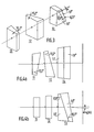
- Figure 1 shows the data for the problem.
- FIG. 2 represents the forms of the differential distortion to be corrected and that introduced by the correction.
- Figure 3 shows a perspective view of the device of the invention.
- Figures 4a and 4b are respectively a horizontal section and a vertical section of an exemplary embodiment of said device.
- FIG. 1 represents the front profile 1 of the fuselage of an airplane whose window 2, having the shape of a portion of a cone, consists of a transparent substance in a determined spectral band.
- the pilot's eye 3 embraces the same field of vision as a camera 4 located at a lower level and operating in said spectral band.
- the image given by the camera is returned to the pilot by means of a "head-up" viewfinder comprising the television monitor 5 collimated at infinity and the semi-transparent mirror 6.
- the display system can project certain useful indications on this image such as the attitude of the aircraft, its speed, the horizon line, etc.
- the difference in the radii of curvature of the window at different levels creates a certain difference in distortion between the observer and the camera so that the superimposition is not perfect. It is therefore this gap that we propose to reduce.
- Figure 2 shows in this case the shape of the differential distortion produced by the aircraft window and that which must be introduced by the take-up device.
- a square abcd is distorted by the porthole in a ⁇ b ⁇ c ⁇ d ⁇ , between the camera and the pilot's eye.
- this device transforms the original square into a rectangle a ⁇ b ⁇ c ⁇ d ⁇ and the curvature introduced into a ⁇ b ⁇ and c ⁇ d ⁇ will be opposite to that produced between the camera and the pilot's eye.
- the take-up is carried out by means of an optical system of modular structure mounted in front of the camera and of which a perspective view is shown in FIG. 3.
- This system performs the correction in the direction of bearing by creating anamorphosis by means of an anamorphic unit with two prisms 11 and 12. These two prisms of the same angle and cut in the same material are arranged head to tail; thus this set does not deflect the beams and therefore does not provide chromatism. If the coefficient of anamorphosis is low, the anamorphosis remains approximately constant in the field.
- correction in the site direction is then ensured by a deflecting prism 13 placed behind the anamorphic assembly.
- the deflecting function introduces a curvature whose concavity is turned towards the base of the prism on the image of a slit parallel to the edge of the prism. This curvature comes from the fact that the prism is not attacked from the same angle depending on whether it is the center or the edge of the slot which is projected.
- the curvature depends on the angle of the prism, its index and the angle of incidence; the image of the optical axis of the camera is thus deviated by an angle ⁇ .
- the nominal aiming direction can be preserved by mechanically tilting the camera + prisms assembly.
- the deflecting prism 13 For certain applications it is necessary to automate the deflecting prism 13 by constituting it of two joined pieces 13 ⁇ and 13 ⁇ whose angles and indices have the appropriate values.
- FIGS. 4a and 4b respectively show a section of the device in the deposit direction (horizontal section) and in the site direction (vertical section).
- angle values of the prisms valid for a given distance between the observer and the camera have been indicated.
- Angle of anamorphic prisms 10.2 °.
- Angles of the deflecting prisms 17.9 ° and 8.5 °.
- Residual chromatism 0.2 bn.
- the proposed solution therefore has the advantage of reducing asymmetric distortion without altering the performance of the recording system.
- the device of the invention can be combined with a flight recording camera to partially solve the distortion problems encountered when superimposing images obtained by two receivers located at levels different from the window.
Landscapes
- Physics & Mathematics (AREA)
- General Physics & Mathematics (AREA)
- Optics & Photonics (AREA)
- Lenses (AREA)
- Telescopes (AREA)
Abstract
Description
- L'invention concerne un dispositif de rattrapage de la distorsion différentielle résultant de l'observation simultanée d'un champ de vue en deux endroits distincts à travers une paroi transparente dans une certaine bande spectrale et dont la forme engendre une distorsion dépourvue de symétrie de révolution, les images obtenues par un premier et par un second récepteur sensibles dans ladite bande spectrale et placés respectivement en chacun desdits endroits étant superposées.
- De nombreux appareils de visée ou d'enregistrement (caméra CCD, vidicon) embarqués à bord d'avions doivent tenir compte de la présence d'un hublot dont la forme (conique par exemple) distord l'image du paysage : un avion en cours d'essai est, par exemple, équipé d'une caméra vidéo dont l'image est renvoyée au moyen d'un viseur "tête haute" afin de venir se superposer à l'image reçue par l'oeil du pilote. Cette caméra ne pouvant être placée proche de la tête du pilote, la distorsion introduite par le hublot de l'avion n'est pas la même pour l'oeil du pilote et la caméra, car les faisceaux optiques traversent le hublot à des hauteurs différentes et cette traversée crée des écarts d'allure asymétrique. Ces écarts peuvent atteindre des valeurs très importantes (de l'ordre du degré) : il est donc nécessaire de les corriger ou du moins de les réduire. Un rattrapage électronique consistant en un traitement numérique de l'image conduit dans certains cas à des systèmes complexes et encombrants.
- L'invention vise à apporter une correction de nature optique qui doit satisfaire aux conditions suivantes :
- Le système ne doit pas altérer la résolution de l'image.
- Il doit être de conception simple, compact et de réglage facile. - La première condition élimine toute possibilité de correction à l'intérieur de la caméra : les solutions du type basculement ou déformation de la surface de réception dégradent généralement la qualité de l'image et demandent des retouches importantes au niveau de l'implantation mécanique et du calcul optique.
- Le système proposé est remarquable en ce que ledit dispositif de rattrapage consiste en un système optique de structure modulaire utilisé en faisceaux parallèles, disposé à l'avant de l'un ou l'autre récepteur et déterminé de façon que la distorsion résultant de la courbure et de la variation de longueur des lignes introduites par ledit système optique soit de sens opposé à ladite distorsion différentielle, ledit dispositif de rattrapage permettant d'obtenir une valeur approchée de correction donnant un résidu de distorsion acceptable.
- Ledit système optique de rattrapage comporte deux fonctions dont l'ordre peut être inversé : une fonction anamorphose créant ladite variation de longueur suivant une direction et une fonction déviation formant ladite courbure suivant le sens d'une autre direction, l'angle desdites directions pouvant être ajusté à une valeur quelconque pour simuler toutes formes de distorsions et lesdites fonctions d'anamorphose et de déviation étant réalisées au moyen de groupes indépendants. Ces deux fonctions étant indépendantes, on peut corriger toute distorsion se ramenant à une courbure, une anamorphose ou une combinaison des deux défauts.
- L'ensemble optique réalisé par exemple au moyen de prismes ne comporte que des surfaces planes et ne dégrade pas l'image s'il est achromatisé et utilisé en faisceaux parallèles.
- La description suivante en regard des dessins annexés, le tout donné à titre d'exemple fera bien comprendre comment l'invention peut être réalisée.
- La figure 1 présente les données du problème.
- La figure 2 représente les formes de la distorsion différentielle à corriger et de celle introduite par la correction.
- La figure 3 montre une vue en perspective du dispositif de l'invention.
- Les figures 4a et 4b sont respectivement une coupe horizontale et une coupe verticale d'un exemple de réalisation dudit dispositif.
- Le dessin de la figure 1 représente le profil avant 1 du fuselage d'un avion dont le hublot 2, ayant la forme d'une portion de cône, est constitué d'une substance transparente dans une bande spectrale déterminée. A travers ce hublot, l'oeil du pilote 3 embrasse le même champ de vision qu'une caméra 4 située à un niveau inférieur et opérant dans ladite bande spectrale. L'image donnée par la caméra est renvoyée au pilote au moyen d'un viseur "tête haute" comportant le moniteur de télévision 5 collimaté à l'infini et le miroir semi-transparent 6. Ainsi, l'image formée par la caméra vient se superposer au paysage vu par le pilote. Le système de visualisation peut projeter sur cette image certaines indications utiles telles que l'attitude de l'avion, sa vitesse, la ligne d'horizon etc. La différence des rayons de courbure du hublot à différents niveaux engendre un certain écart de distorsion entre l'observateur et la caméra de sorte que la superposition n'est pas parfaite. C'est donc cet écart que l'on se propose de réduire.
- La figure 2 montre dans ce cas la forme de la distorsion différentielle produite par le hublot de l'avion et celle qui doit être introduite par le dispositif de rattrapage.
- Un carré abcd est distordu par le hublot en aʹbʹcʹdʹ, entre la caméra et l'oeil du pilote. Les lignes aʹdʹ et bʹcʹ restant perpendiculaires au côté ab du carré, on peut proposer dans le cas de cet exemple un dispositif correcteur réalisant une anamorphose dans le sens gisement et une courbure dans le sens site.
- Ainsi ce dispositif transforme le carré d'origine en un rectangle aʺbʺcʺdʺ et la courbure introduite en aʹʺbʹʺ et cʹʺdʹʺ sera de sens oppposé à celle produite entre la caméra et l'oeil du pilote.
- Selon l'invention, le rattrapage est effectué au moyen d'un système optique de structure modulaire monté devant la caméra et dont une vue en perspective est représentée sur la figure 3.
- Ce système effectue la correction dans le sens gisement en créant l'anamorphose au moyen d'un ensemble anamorphoseur à deux prismes 11 et 12. Ces deux prismes de même angle et taillés dans le même matériau sont disposés tête bêche ; ainsi cet ensemble ne dévie pas les faisceaux et n'apporte donc pas de chromatisme. Si le coefficient d'anamorphose est faible, l'anamorphose reste à peu près constante dans le champ.
- La correction dans le sens site est ensuite assurée par un prisme déviateur 13 placé derrière l'ensemble anamorphoseur. La fonction déviatrice introduit sur l'image d'une fente parallèle à l'arête du prisme une courbure dont la concavité est tournée vers la base du prisme. Cette courbure provient du fait que le prisme n'est pas attaqué sous le même angle selon que c'est le centre ou le bord de la fente qui est projeté.
- La courbure dépend de l'angle du prisme, de son indice et de l'angle d'incidence ; l'image de l'axe optique de la caméra est ainsi déviée d'un angle α.
- On peut conserver la direction nominale de visée en basculant mécaniquement l'ensemble caméra + prismes.
- Pour certaines applications il est nécessaire d'achromatiser le prisme déviateur 13 en le constituant de deux morceaux accolés 13ʹ et 13ʺ dont les angles et les indices ont les valeurs appropriées.
- Les figures 4a et 4b montrent respectivement une coupe du dispositif dans le sens gisement (coupe horizontale) et dans le sens site (coupe verticale).
- Pour un exemple d'application on a indiqué les valeurs d'angle des prismes valables pour une distance donnée entre l'observateur et la caméra.
Angle des prismes anamorphoseurs : 10,2°.
Angles des prismes déviateurs : 17,9° et 8,5°.
Chromatisme résiduel : 0,2 mrd.
Déviation de l'axe optique caméra : α = 4,046°. - La solution proposée présente donc l'avantage de réduire une distorsion asymétrique sans altérer les performances du système d'enregistrement.
- De conception simple et d'encombrement réduit, le dispositif de l'invention peut être associé à une caméra d'enregistrement en vol pour résoudre en partie les problèmes de distorsion rencontrés lors de la superposition d'images obtenues par deux récepteurs situés à des niveaux différents du hublot.
Claims (6)
Applications Claiming Priority (2)
| Application Number | Priority Date | Filing Date | Title |
|---|---|---|---|
| FR8616234A FR2607269B1 (fr) | 1986-11-21 | 1986-11-21 | Dispositif de rattrapage de distorsion |
| FR8616234 | 1986-11-21 |
Publications (2)
| Publication Number | Publication Date |
|---|---|
| EP0270166A1 true EP0270166A1 (fr) | 1988-06-08 |
| EP0270166B1 EP0270166B1 (fr) | 1992-06-03 |
Family
ID=9341066
Family Applications (1)
| Application Number | Title | Priority Date | Filing Date |
|---|---|---|---|
| EP87202248A Expired - Lifetime EP0270166B1 (fr) | 1986-11-21 | 1987-11-18 | Dispositif de rattrapage de distorsion |
Country Status (5)
| Country | Link |
|---|---|
| US (1) | US4840465A (fr) |
| EP (1) | EP0270166B1 (fr) |
| JP (1) | JP2567877B2 (fr) |
| DE (1) | DE3779580T2 (fr) |
| FR (1) | FR2607269B1 (fr) |
Cited By (1)
| Publication number | Priority date | Publication date | Assignee | Title |
|---|---|---|---|---|
| EP0314243B1 (fr) * | 1987-10-27 | 1993-04-07 | Telecommunications Radioelectriques Et Telephoniques T.R.T. | Dispositif de rattrapage de la distorsion totale engendrée par la forme d'une paroi transparente |
Families Citing this family (11)
| Publication number | Priority date | Publication date | Assignee | Title |
|---|---|---|---|---|
| US5005009A (en) * | 1988-02-16 | 1991-04-02 | K. W. Muth Company, Inc. | Method and apparatus for multiple object viewing |
| US5128659A (en) * | 1988-02-16 | 1992-07-07 | K. W. Muth Company, Inc. | Instrument display apparatus |
| US5013135A (en) * | 1989-07-10 | 1991-05-07 | Matsushita Electric Industrial Co., Ltd. | Head-up display with two fresnel lenses |
| DE4028359C2 (de) * | 1989-09-06 | 1994-05-19 | Asahi Optical Co Ltd | Bildstabilisierungseinrichtung |
| FR2760924B1 (fr) | 1997-03-14 | 1999-06-04 | Thomson Csf | Architecture optique pour systeme de vision infrarouge |
| FR2833717B1 (fr) * | 2001-12-14 | 2004-02-20 | Thales Sa | Combinaison optique multichamp de type cassegrain |
| DE102004012032A1 (de) * | 2004-03-11 | 2005-09-29 | Carl Zeiss Jena Gmbh | Anzeigevorrichtung und Anzeigeverfahren |
| JP5686011B2 (ja) * | 2011-03-22 | 2015-03-18 | セイコーエプソン株式会社 | 画像リレー光学系及びこれを備える虚像表示装置 |
| KR102036318B1 (ko) * | 2012-02-16 | 2019-11-26 | 삼성전자주식회사 | 전자 장치의 카메라 왜곡 현상 방지를 위한 윈도우 |
| JP6048514B2 (ja) * | 2015-01-19 | 2016-12-21 | セイコーエプソン株式会社 | 画像リレー光学系 |
| US10414515B2 (en) * | 2016-11-23 | 2019-09-17 | Gulfstream Aerospace Corporation | Aircraft and deployable vision systems for aircraft |
Citations (5)
| Publication number | Priority date | Publication date | Assignee | Title |
|---|---|---|---|---|
| US2821111A (en) * | 1954-09-22 | 1958-01-28 | Taylor Taylor & Hobson Ltd | Anamorphotic optical systems |
| FR1222433A (fr) * | 1958-04-15 | 1960-06-09 | Système de prismes achromatiques à distance focale variable pour modifier, allonger et comprimer des images | |
| GB1296573A (fr) * | 1970-09-22 | 1972-11-15 | ||
| WO1981000499A1 (fr) * | 1979-07-30 | 1981-02-19 | Singer Co | Illumination optique et compensateur de distorsion |
| EP0025335A1 (fr) * | 1979-09-05 | 1981-03-18 | The Marconi Company Limited | Dispositifs de visée stabilisables et système de commande de canon de char blindé utilisant un tel dispositif |
Family Cites Families (2)
| Publication number | Priority date | Publication date | Assignee | Title |
|---|---|---|---|---|
| US4245890A (en) * | 1979-01-02 | 1981-01-20 | The United States Of America As Represented By The Secretary Of The Army | Gradient index of refraction for missile seekers |
| US4580879A (en) * | 1983-09-06 | 1986-04-08 | Storage Technology Partners Ii | In-line optical anamorphic beam expander/contractor |
-
1986
- 1986-11-21 FR FR8616234A patent/FR2607269B1/fr not_active Expired
-
1987
- 1987-11-18 DE DE8787202248T patent/DE3779580T2/de not_active Expired - Fee Related
- 1987-11-18 EP EP87202248A patent/EP0270166B1/fr not_active Expired - Lifetime
- 1987-11-19 US US07/123,034 patent/US4840465A/en not_active Expired - Fee Related
- 1987-11-20 JP JP62292219A patent/JP2567877B2/ja not_active Expired - Lifetime
Patent Citations (5)
| Publication number | Priority date | Publication date | Assignee | Title |
|---|---|---|---|---|
| US2821111A (en) * | 1954-09-22 | 1958-01-28 | Taylor Taylor & Hobson Ltd | Anamorphotic optical systems |
| FR1222433A (fr) * | 1958-04-15 | 1960-06-09 | Système de prismes achromatiques à distance focale variable pour modifier, allonger et comprimer des images | |
| GB1296573A (fr) * | 1970-09-22 | 1972-11-15 | ||
| WO1981000499A1 (fr) * | 1979-07-30 | 1981-02-19 | Singer Co | Illumination optique et compensateur de distorsion |
| EP0025335A1 (fr) * | 1979-09-05 | 1981-03-18 | The Marconi Company Limited | Dispositifs de visée stabilisables et système de commande de canon de char blindé utilisant un tel dispositif |
Non-Patent Citations (1)
| Title |
|---|
| OPTICAL ENGINEERING, vol. 21, no. 1, janvier-février 1982, pages 96-104, Society of Photo-Optical Instrumentation Engineers, Bellingham, Washington, US; Y. NETZER: "Line-of-sight steering and stabilization" * |
Cited By (1)
| Publication number | Priority date | Publication date | Assignee | Title |
|---|---|---|---|---|
| EP0314243B1 (fr) * | 1987-10-27 | 1993-04-07 | Telecommunications Radioelectriques Et Telephoniques T.R.T. | Dispositif de rattrapage de la distorsion totale engendrée par la forme d'une paroi transparente |
Also Published As
| Publication number | Publication date |
|---|---|
| JPS63142313A (ja) | 1988-06-14 |
| DE3779580T2 (de) | 1993-01-21 |
| US4840465A (en) | 1989-06-20 |
| FR2607269A1 (fr) | 1988-05-27 |
| JP2567877B2 (ja) | 1996-12-25 |
| EP0270166B1 (fr) | 1992-06-03 |
| DE3779580D1 (de) | 1992-07-09 |
| FR2607269B1 (fr) | 1989-03-24 |
Similar Documents
| Publication | Publication Date | Title |
|---|---|---|
| EP0270166B1 (fr) | Dispositif de rattrapage de distorsion | |
| FR2784201A1 (fr) | Dispositif optique pour viseur de casque comportant un miroir diffractif | |
| EP0487385B1 (fr) | Dispositif de visualisation collimaté à miroir sphérique hors d'axe pour simulateur | |
| EP0399865A1 (fr) | Dispositif optique pour l'introduction d'une image collimatée dans le champ visuel d'un observateur, et casque comportant au moins un tel dispositif | |
| EP3596533A1 (fr) | Dispositif de projection aérienne et dématérialisée d'une image numérique ou d'une séquence d'images numériques, en particulier d'une image auto-stéréoscopique ou d'une séquence d'images auto-stéréoscopiques | |
| EP0353138B1 (fr) | Dispositif optique multispectral à miroirs | |
| EP0189217B1 (fr) | Analyseur optico-mécanique ayant un champ de télémétrie fixe | |
| FR2725335A1 (fr) | Systeme d'objectif d'imageur multiple | |
| EP0127914B1 (fr) | Viseur panoramique sans rotation d'image à plusieurs champs | |
| EP0314243A1 (fr) | Dispositif de rattrapage de la distorsion totale engendrée par la forme d'une paroi transparente | |
| EP0068932B1 (fr) | Têtes de visée d'installations périscopiques, notamment pour sous-marins | |
| WO2019238949A1 (fr) | Dispositif de veille proximale | |
| EP0738077B1 (fr) | Téléviseur ou moniteur vidéo compact du type à rétroprojection | |
| EP0130869A1 (fr) | Dispositif à imagerie vidéo, notamment pour autodirecteur | |
| EP0187687B1 (fr) | Analyseur optico-mécanique ayant un champ de télémétrie fixe | |
| EP0696868B1 (fr) | Dispositif de balayage en particulier pour système d'imagerie | |
| FR2653905A1 (fr) | Dispositif optique de correction des defauts introduits par un hublot spherique utilise hors d'axe. | |
| EP4235253B1 (fr) | Téléscope à cinq miroirs | |
| EP0610635B1 (fr) | Dispositif optique de calibration pour caméra thermique | |
| EP1279989A2 (fr) | Dispositif de visualisation d'images par projection, comprenant des filtres dichroiques à gradient | |
| WO1998002769A1 (fr) | Systeme optique a rotation d'image et systeme d'observation le comportant | |
| EP0614103B1 (fr) | Lunette à miroirs oscillants pour la vision infrarouge | |
| FR2552557A1 (fr) | Microscope | |
| EP0104115A2 (fr) | Dispositif viseur à champ instantané agrandi comportant un miroir, et procédé de fabrication de ce miroir | |
| EP3798710A1 (fr) | Telescope de type cassegrain a plan de focal segmente |
Legal Events
| Date | Code | Title | Description |
|---|---|---|---|
| PUAI | Public reference made under article 153(3) epc to a published international application that has entered the european phase |
Free format text: ORIGINAL CODE: 0009012 |
|
| AK | Designated contracting states |
Kind code of ref document: A1 Designated state(s): DE FR GB IT NL SE |
|
| 17P | Request for examination filed |
Effective date: 19881206 |
|
| 17Q | First examination report despatched |
Effective date: 19901102 |
|
| GRAA | (expected) grant |
Free format text: ORIGINAL CODE: 0009210 |
|
| AK | Designated contracting states |
Kind code of ref document: B1 Designated state(s): DE FR GB IT NL SE |
|
| REF | Corresponds to: |
Ref document number: 3779580 Country of ref document: DE Date of ref document: 19920709 |
|
| ITF | It: translation for a ep patent filed | ||
| GBT | Gb: translation of ep patent filed (gb section 77(6)(a)/1977) | ||
| PLBE | No opposition filed within time limit |
Free format text: ORIGINAL CODE: 0009261 |
|
| STAA | Information on the status of an ep patent application or granted ep patent |
Free format text: STATUS: NO OPPOSITION FILED WITHIN TIME LIMIT |
|
| 26N | No opposition filed | ||
| REG | Reference to a national code |
Ref country code: GB Ref legal event code: 732E |
|
| NLS | Nl: assignments of ep-patents |
Owner name: THOMSON-TRT DEFENSE TE PARIJS, FRANKRIJK. |
|
| ITPR | It: changes in ownership of a european patent |
Owner name: CESSIONE;THOMSON - TRT DEFENSE |
|
| EAL | Se: european patent in force in sweden |
Ref document number: 87202248.8 |
|
| PGFP | Annual fee paid to national office [announced via postgrant information from national office to epo] |
Ref country code: NL Payment date: 19951013 Year of fee payment: 9 |
|
| PGFP | Annual fee paid to national office [announced via postgrant information from national office to epo] |
Ref country code: SE Payment date: 19951020 Year of fee payment: 9 |
|
| ITPR | It: changes in ownership of a european patent |
Owner name: OFFERTA DI LICENZA AL PUBBLICO;PUBBLICO |
|
| REG | Reference to a national code |
Ref country code: GB Ref legal event code: 746 Effective date: 19960327 |
|
| PG25 | Lapsed in a contracting state [announced via postgrant information from national office to epo] |
Ref country code: SE Effective date: 19961119 |
|
| PG25 | Lapsed in a contracting state [announced via postgrant information from national office to epo] |
Ref country code: NL Effective date: 19970601 |
|
| NLV4 | Nl: lapsed or anulled due to non-payment of the annual fee |
Effective date: 19970601 |
|
| EUG | Se: european patent has lapsed |
Ref document number: 87202248.8 |
|
| PGFP | Annual fee paid to national office [announced via postgrant information from national office to epo] |
Ref country code: DE Payment date: 19981016 Year of fee payment: 12 |
|
| PG25 | Lapsed in a contracting state [announced via postgrant information from national office to epo] |
Ref country code: DE Free format text: LAPSE BECAUSE OF NON-PAYMENT OF DUE FEES Effective date: 20000901 |
|
| REG | Reference to a national code |
Ref country code: GB Ref legal event code: IF02 |
|
| PGFP | Annual fee paid to national office [announced via postgrant information from national office to epo] |
Ref country code: FR Payment date: 20031110 Year of fee payment: 17 |
|
| PGFP | Annual fee paid to national office [announced via postgrant information from national office to epo] |
Ref country code: GB Payment date: 20031112 Year of fee payment: 17 |
|
| PG25 | Lapsed in a contracting state [announced via postgrant information from national office to epo] |
Ref country code: GB Free format text: LAPSE BECAUSE OF NON-PAYMENT OF DUE FEES Effective date: 20041118 |
|
| GBPC | Gb: european patent ceased through non-payment of renewal fee |
Effective date: 20041118 |
|
| PG25 | Lapsed in a contracting state [announced via postgrant information from national office to epo] |
Ref country code: FR Free format text: LAPSE BECAUSE OF NON-PAYMENT OF DUE FEES Effective date: 20050729 |
|
| REG | Reference to a national code |
Ref country code: FR Ref legal event code: ST |
|
| PG25 | Lapsed in a contracting state [announced via postgrant information from national office to epo] |
Ref country code: IT Free format text: LAPSE BECAUSE OF NON-PAYMENT OF DUE FEES;WARNING: LAPSES OF ITALIAN PATENTS WITH EFFECTIVE DATE BEFORE 2007 MAY HAVE OCCURRED AT ANY TIME BEFORE 2007. THE CORRECT EFFECTIVE DATE MAY BE DIFFERENT FROM THE ONE RECORDED. Effective date: 20051118 |