EP0270148B1 - Radar apparatus for measuring its distance to an object - Google Patents
Radar apparatus for measuring its distance to an object Download PDFInfo
- Publication number
- EP0270148B1 EP0270148B1 EP87202059A EP87202059A EP0270148B1 EP 0270148 B1 EP0270148 B1 EP 0270148B1 EP 87202059 A EP87202059 A EP 87202059A EP 87202059 A EP87202059 A EP 87202059A EP 0270148 B1 EP0270148 B1 EP 0270148B1
- Authority
- EP
- European Patent Office
- Prior art keywords
- link
- wave
- radar device
- digital processing
- memory
- Prior art date
- Legal status (The legal status is an assumption and is not a legal conclusion. Google has not performed a legal analysis and makes no representation as to the accuracy of the status listed.)
- Expired - Lifetime
Links
Images


Classifications
-
- G—PHYSICS
- G01—MEASURING; TESTING
- G01S—RADIO DIRECTION-FINDING; RADIO NAVIGATION; DETERMINING DISTANCE OR VELOCITY BY USE OF RADIO WAVES; LOCATING OR PRESENCE-DETECTING BY USE OF THE REFLECTION OR RERADIATION OF RADIO WAVES; ANALOGOUS ARRANGEMENTS USING OTHER WAVES
- G01S13/00—Systems using the reflection or reradiation of radio waves, e.g. radar systems; Analogous systems using reflection or reradiation of waves whose nature or wavelength is irrelevant or unspecified
- G01S13/02—Systems using reflection of radio waves, e.g. primary radar systems; Analogous systems
- G01S13/06—Systems determining position data of a target
- G01S13/08—Systems for measuring distance only
- G01S13/32—Systems for measuring distance only using transmission of continuous waves, whether amplitude-, frequency-, or phase-modulated, or unmodulated
- G01S13/34—Systems for measuring distance only using transmission of continuous waves, whether amplitude-, frequency-, or phase-modulated, or unmodulated using transmission of continuous, frequency-modulated waves while heterodyning the received signal, or a signal derived therefrom, with a locally-generated signal related to the contemporaneously transmitted signal
Definitions
- the present invention relates to a radar device for measuring the distance "h" which separates it from an object, device comprising transmission means for transmitting a frequency modulated wave towards the object, reception means comprising mixing means to receive the wave after reflection on the object and to provide a beat wave between the emitted wave and the received wave, rapid digital processing means for carrying out a time-frequency transformation operation on the beat wave , output means for providing the indication of the distance "h” and management means constituted from a microprocessor executing the instructions of a program implanted in a read-only memory while a first link is provided for connect the management means to the output means, a second link to connect the management means to the reception means, a third link to connect the management means to the means ns fast digital processing, a fourth link between the management means and the transmission means, said links preferably being bidirectional.
- the type of application targeted more particularly by the invention is the determination of the altitude of an aircraft, the device being carried on board the latter while the object is constituted by the ground.
- a device of the aforementioned kind is described in another patent of the United States of America No. 4,268,828.
- This known device uses management means constituted from a programmable microprocessor which acts on the means of reception so that the measurements to determine "h" can be made at adequate levels and from there good information can be provided to the means of exit.
- the fast digital processing means include a frequency temporal transformation device operating on the output signals d a device for correlating the beat signals, and in that the program installed in the read-only memory of the management means contains instructions for carrying out a time-frequency transformation operation to compensate for a failure of the fast digital processing means.
- the reference 1 shown in Figure 1 indicates the device of the invention.
- Reference 2 indicates the object separated by a distance "h" from the device.
- the object 2 is the surface of the ground while the device 1 is on board an aircraft not shown.
- This wave is transmitted in space from a transmitting antenna 5 which is connected to the output of a transmitting amplifier 7.
- This amplifier 7 amplifies the signal supplied by an oscillator 9 with frequency control by voltage .
- a sawtooth signal generator bearing the reference 11 supplies the control voltage for this oscillator 9.
- the radar device 1 To receive this R wave (t), the radar device 1 is provided with a reception antenna 15, with a high frequency reception amplifier 17.
- a mixer circuit 20 mixes the received wave amplified by amplifier 17 with the wave of emission sampled by means of a directional coupler 22 inserted between the oscillator 9 and the emission amplifier 7.
- the signal M (t) is advantageously processed in digital form; for this, an analog-digital converter 25 has been provided to convert this signal M (t) which has previously undergone an amplification provided by a beat amplifier 27.
- the analog-to-digital converter 25 supplies digital samples to a fast digital processing unit 30 which is designed to form frequency spectra thereof. These spectra are then processed by a management unit 35 so as to provide the user with the value of the distance "h" on an indicator 55.
- the radar device is provided with a management assembly 50 in particular for supplying the user with the value "h" via a display unit 55 and for controlling in particular the sawtooth signal generator 11 and also the set of fast digital processing.
- the management assembly controls the level of the emission wave by acting on an attenuation command incorporated in the emission amplifier 7.
- an FSCX bundle which connects them to the management assembly 50. It goes without saying that in practice the different links between the elements and the management assembly may not borrow the same route and therefore do not necessarily have the physical appearance of a bundle of wires.
- FIG. 2 the management assembly 50, the fast digital processing assembly 30 and the display unit 55 are shown in more detail.
- the management assembly is constituted around a microprocessor unit 100 comprising, as is well known, the microprocessor proper ⁇ Pg (for example the 6809 manufactured by MOTOROLA), a random access memory RAM and a read only memory ROM in which is saved the program desired by the user.
- This unit communicates externally via a BSDG line to transmit data and a BADG line to transmit address codes.
- the assembly 50 includes an address code decoder which decodes the codes transmitted by the BADG line; this decoder supplies different signals CZF, CAFF, RG, WG, CDS, CTM, CATT which are transmitted to different elements of the radar device of the invention via the beam FSCX.
- the assembly 50 also includes a programmable interface circuit 115 (for example the circuit registered 6820, manufactured by MOTOROLA), the accesses of which are connected to wires forming part of the FSCX bundle.
- the digital processing assembly is also formed of a microprocessor unit 200 comprising a microprocessor proper functioning quickly (for example the TMS 320 manufactured by Texas Instruments) a ROM read only memory and a random access memory RAM; this unit is programmed to perform fast Fourier transformations (we can consult the article by SURENDER HAGAR et al entitled “ ⁇ C builds FFT band spectrum analyzer” published in the collection "Signal Processing with the TMS 320” published by Texas Instruments).
- the Fourier transformation is carried out on the output signals of an autocorrelation device 203 of a type described in French patent application No. 85 12 337 filed August 13, 1985 in the name of the Claimant.
- the output signals of this device are transmitted by a data transmission line BSDF connected to the unit 200.
- the input of the signals to autocorrelate of the device is connected to the output of the digital-analog converter 25 via a register 207.
- a second bidirectional register 210 connects this input to the line BSDF.
- the register 207 is put in the blocked state and preset data coming from the unit 200 can be injected into the device and, from there, it becomes possible to check if this data has been correctly correlated.
- an address code decoder 215 connected to the BADF line transmitting address codes from the unit 200; this decoder 215 provides notably WF and RF signals.
- the assembly 30 is connected to the FSCX bundle by means of two memories 218 and 220 of the first input data, first output data type (FIFO memory of the LS222 type).
- the input of memory 218 is connected via a bidirectional register 222 to the line BSDF and its output to the line BSDG via the beam FSCX.
- the input of the memory 220 is connected to the line BSDG always via the beam FSCX, while its output is connected to the line BSDF via the register 222.
- the signals WF and RF allow respectively to write in the memory 210 and to read in the memory 220, the data to be written and to be read concerning the unit 200.
- the signals WG and RG processing by the beam FSCX allow respectively the writing in the memory 220 and the reading of the contents of the memory 218, the last data to be written and read concerning the unit 100.
- the signal CZF passing through the line BSCC can be used to initialize or reinitialize the unit 200.
- the display unit 55 makes it possible to display the result supplied by the unit 100 via the line BSDG passing through the beam FSCX. This is the CAFF signal assigned to unit 55 which fixes the destination of the data transmitted by the BSDG line.
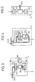
- FIG 3 there is shown a way in which one could control the emission level by acting on the emission amplifier 7.
- This amplifier is formed by a constant gain amplifier 300 followed by a PIN diode attenuator switchable 302.
- the switching of these diodes is determined by a transcoding circuit 305 which converts the continuous code into a register 310 into a switching code.
- the inputs of this register 310 are connected to the line BSDG via the beam FSCX . For the data transmitted by these lines to be recorded in the register 310, the CATT signal passing through the FSCX beam must be active.
- FIG. 4 shows how the sawtooth signal generator is controlled by the management assembly 50.
- the generator is developed around a circuit 350 described in European patent No. 0 113 975.
- the duration of the sawtooth is determined by a code contained in a register 360.
- the inputs of this register 310 are linked to the line BSDG via the beam FSCX when the signal CDS also passing through this beam is active.
- a timing circuit 370 is added to circuit 350.
- This timing circuit 370 (for example the circuit registered 6840 and manufactured by MOTOROLA) determines the actual duration of the sawtooth and this duration is communicated to the management unit by l intermediary of the BSDG line passing through the FSCX beam. This communication takes place only if the CTM signal passing through the FSCX beam is active.
- FIG. 5 shows how the gain of the reception amplifier 27 is varied.
- This amplifier is formed by two fixed gain amplifiers 400 and 402 connected in cascade and between which is an attenuator 405.
- This attenuator is in fact a logarithmic digital-analog converter (for example of the type registered AD7118); this converter provides an output signal which is both dependent on the input code and the input signal.
- the entry code comes from circuit 115 passing through the FSCX beam.
Description
La présente invention concerne un dispositif radar pour mesurer la distance "h" qui le sépare d'un objet, dispositif comportant des moyens d'émission pour émettre vers l'objet une onde modulée en fréquence, des moyens de réception comprenant des moyens de mélange pour recevoir l'onde après réflexion sur l'objet et pour fournir une onde de battement entre l'onde émise et l'onde reçue, des moyens de traitement numérique rapide pour effectuer une opération de transformation temporelle-fréquentielle sur l'onde de battement, des moyens de sortie pour fournir l'indication de la distance "h" et des moyens de gestion constitués à partir d'un microprocesseur executant les instructions d'un programme implanté dans une mémoire morte tandis qu'il est prévu une première liaison pour relier les moyens de gestion aux moyens de sortie, une deuxième liaison pour relier les moyens de gestion aux moyens de réception, une troisième liaison pour relier les moyens de gestion aux moyens de traitement numérique rapide, une quatrième liaison entre les moyens de gestion et les moyens d'émission, lesdites liaisons étant de préférence bidirectionnelles.The present invention relates to a radar device for measuring the distance "h" which separates it from an object, device comprising transmission means for transmitting a frequency modulated wave towards the object, reception means comprising mixing means to receive the wave after reflection on the object and to provide a beat wave between the emitted wave and the received wave, rapid digital processing means for carrying out a time-frequency transformation operation on the beat wave , output means for providing the indication of the distance "h" and management means constituted from a microprocessor executing the instructions of a program implanted in a read-only memory while a first link is provided for connect the management means to the output means, a second link to connect the management means to the reception means, a third link to connect the management means to the means ns fast digital processing, a fourth link between the management means and the transmission means, said links preferably being bidirectional.
Le genre d'application visé plus particulièrement par l'invention est la détermination de l'altitude d'un aéronef, le dispositif étant embarqué à bord de ce dernier tandis que l'objet est constitué par le sol.The type of application targeted more particularly by the invention is the determination of the altitude of an aircraft, the device being carried on board the latter while the object is constituted by the ground.
Depuis quelque temps, on s'efforce d'utiliser pour cette détermination de distance des circuits de traitement numérique (voir par exemple le brevet des Etats-Unis d'Amérique N° 4 568 938).For some time, efforts have been made to use digital processing circuits for this determination of distance (see, for example, United States Patent No. 4,568,938).
Un dispositif du genre précité est décrit dans un autre brevet des Etats-Unis d'Amérique N° 4 268 828. Ce dispositif connu utilise des moyens de gestion constitués à partir d'un microprocesseur programmable qui agit sur les moyens de réception afin que les mesures pour déterminer "h" puissent s'effectuer aux niveaux adéquats et de là on peut fournir de bonnes informations aux moyens de sortie.A device of the aforementioned kind is described in another patent of the United States of America No. 4,268,828. This known device uses management means constituted from a programmable microprocessor which acts on the means of reception so that the measurements to determine "h" can be made at adequate levels and from there good information can be provided to the means of exit.
Cependant avec ce dispositif on est confronté avec l'inconvénient que les moyens de traitement numérique rapide, surtout lorsqu'ils présentent un certain degré de sophistication, sont les éléments les plus sujets aux défaillances.However, with this device, we are confronted with the drawback that the rapid digital processing means, especially when they have a certain degree of sophistication, are the elements most prone to failures.
Pour donner une information sur "h" malgré la défaillance des moyens de traitement rapide, un dispositif du genre mentionné dans le préambule est remarquable en ce que les moyens de traitement numérique rapide comportent un organe de transformation temporelle fréquentielle opérant sur les signaux de sortie d'un dispositif de corrélation des signaux de battement, et en ce que le programme implanté dans la mémoire morte des moyens de gestion contient des instructions pour effectuer une opération de transformation temporelle-fréquentielle pour suppléer à une défaillance des moyens de traitement numérique rapide.To give information on "h" despite the failure of the fast processing means, a device of the kind mentioned in the preamble is remarkable in that the fast digital processing means include a frequency temporal transformation device operating on the output signals d a device for correlating the beat signals, and in that the program installed in the read-only memory of the management means contains instructions for carrying out a time-frequency transformation operation to compensate for a failure of the fast digital processing means.
La présente invention sera mieux comprise à l'aide de la description suivante, accompagnée des dessins ci-annexés. Sur ces dessins :
- La figure 1 montre un dispositif radar conforme à l'invention.
- La figure 2 montre plus en détail les moyens de traitement rapide reliés avec les moyens de gestion ainsi que l'unité de visualisation.
- La figure 3 montre la commande de niveau des moyens d'émission.
- La figure 4 montre la commande de fréquence des moyens d'émission.
- La figure 5 montre la commande de gain des moyens de réception.
- Figure 1 shows a radar device according to the invention.
- Figure 2 shows in more detail the fast processing means connected with the management means as well as the display unit.
- Figure 3 shows the level control of the transmission means.
- FIG. 4 shows the frequency control of the transmission means.
- FIG. 5 shows the gain control of the reception means.
La référence 1 portée sur la figure 1 indique le dispositif de l'invention. La référence 2 indique l'objet séparé d'une distance "h" du dispositif. Dans l'exemple décrit se rapportant à l'application envisagée de radionavigation, l'objet 2 est la surface du sol tandis que le dispositif 1 est embarqué à bord d'un aéronef non représenté.The reference 1 shown in Figure 1 indicates the device of the invention. Reference 2 indicates the object separated by a distance "h" from the device. In the example described relating to the envisaged application of radio navigation, the object 2 is the surface of the ground while the device 1 is on board an aircraft not shown.
Pour mesurer cette distance "h", on utilise une onde E(t) modulée linéairement en fréquence à partir d'une fréquence porteuse f₀ (par exemple 4 GHz) sur une plage de fréquence ΔF, ce qui s'écrit :
![]()
pour t variant dans les laps de temps T où la dent de scie se produit.
A est une constante définissant l'amplitude de l'onde.To measure this distance "h", an E (t) wave is used which is linearly frequency modulated from a carrier frequency f par (for example 4 GHz) over a frequency range ΔF, which is written:
![]()
for t varying in the period of time T where the sawtooth occurs.
A is a constant defining the amplitude of the wave.
Cette onde est émise dans l'espace à partir d'une antenne d'émission 5 qui est connectée à la sortie d'un amplificateur d'émission 7. Cet amplificateur 7 amplifie le signal fourni par un oscillateur 9 à commande de fréquence par tension. Un générateur de signaux en dents de scie portant la référence 11 fournit la tension de commande pour cet oscillateur 9. L'onde E(t) est réfléchie par l'objet 2 de sorte que l'onde reçue s'écrit :
![]()
où B est une constante définissant le niveau reçu et τ représente le retard entre l'onde émise et l'onde réfléchie.This wave is transmitted in space from a transmitting antenna 5 which is connected to the output of a transmitting
![]()
where B is a constant defining the received level and τ represents the delay between the emitted wave and the reflected wave.
Pour recevoir cette onde R(t), le dispositif radar 1 est muni d'une antenne de réception 15, d'un amplificateur haute fréquence de réception 17.To receive this R wave (t), the radar device 1 is provided with a
Un circuit mélangeur 20 effectue le mélange de l'onde reçue amplifiée par l'amplificateur 17 avec l'onde d'émission prélevée au moyen d'un coupleur directif 22 inséré entre l'oscillateur 9 et l'amplificateur d'émission 7. Ce mélangeur 20 fournit une onde M(t) :
![]()
où C représente une constante.
De la fréquence "fb" du signal M(t) on déduit la distance "h" :
![]()
(c = vitesse de la lumière)
d'où :
Le signal M(t) est d'une façon avantageuse traité sous forme numérique ; pour cela, on a prévu un convertisseur analogique-numérique 25 pour convertir ce signal M(t) qui a subi au-paravant une amplification apportée par un amplificateur de battement 27.A
![]()
where C represents a constant.
From the frequency "fb" of the signal M (t) we deduce the distance "h":
![]()
(c = speed of light)
from where :
The signal M (t) is advantageously processed in digital form; for this, an analog-
Le convertisseur analogique-numérique 25 fournit des échantillons numériques à un ensemble de traitement numérique rapide 30 qui est prévu pour en former des spectres en fréquence. Ces spectres sont ensuite traités par un ensemble de gestion 35 de façon à fournir à l'utilisateur la valeur de la distance "h" sur un indicateur 55.The analog-to-
Le dispositif radar est muni d'un ensemble de gestion 50 pour fournir notamment à l'utilisateur la valeur "h" par l'intermédiaire d'une unité de visualisation 55 et pour piloter notamment le générateur de signaux de dents de scie 11 et aussi l'ensemble de traitement numérique rapide. En outre, l'ensemble de gestion pilote le niveau de l'onde d'émission en agissant sur une commande d'atténuation incorporée à l'amplificateur d'émission 7. Pour montrer le pilotage de ces éléments par l'ensemble de gestion, on a représenté sur les figures un faisceau FSCX qui les relie à l'ensemble de gestion 50. Il va de soi qu'en pratique les différentes liaisons entre les éléments et l'ensemble de gestion peuvent ne pas emprunter le même parcours et de ce fait n'ont pas forcément l'aspect physique d'un faisceau de fils.The radar device is provided with a
A la figure 2, on a représenté plus en détail l'ensemble de gestion 50, l'ensemble de traitement numérique rapide 30 et l'unité de visualisation 55.In FIG. 2, the
L'ensemble de gestion est constitué autour d'une unité à microprocesseur 100 comprenant, comme cela est bien connu, le microprocesseur proprement dit µPg (par exemple le 6809 fabriqué par MOTOROLA), une mémoire vive RAM et une mémoire morte ROM dans laquelle est enregistré le programme souhaité par l'utilisateur. Cette unité communique à l'extérieur par l'intermédiaire d'une ligne BSDG pour transmettre des données et d'une ligne BADG pour transmettre des codes d'adresses.The management assembly is constituted around a
L'ensemble 50 comporte un décodeur de codes d'adresse qui décode les codes transmis par la ligne BADG ; ce décodeur fournit différents signaux CZF, CAFF, RG, WG, CDS, CTM, CATT qui sont transmis vers différents éléments du dispositif radar de l'invention par l'intermédiaire du faisceau FSCX. L'ensemble 50 comporte aussi un circuit d'interface 115 programmable (par exemple le circuit immatriculé 6820, fabriqué par MOTOROLA) dont les accès sont reliés à des fils faisant partie du faisceau FSCX.The
L'ensemble de traitement numérique est formé aussi d'une unité à microprocesseur 200 comportant un microprocesseur proprement dit fonctionnant rapidement (par exemple le TMS 320 fabriqué par Texas Instruments) une mémoire morte ROM et une mémoire vive RAM ; cette unité est programmée pour effectuer des transformations de Fourier rapide (on pourra à ce sujet consulter l'article de SURENDER HAGAR et al intitulé "µC builds FFT band spectrum analyzer" paru dans le recueil "Signal Processing with the TMS 320" édité par Texas Instruments). La transformation de Fourier est effectuée sur les signaux de sortie d'un dispositif d'autocorrélation 203 d'un type décrit dans la demande de brevet français N° 85 12 337 déposée le 13 août 1985 au nom de la Demanderesse. Les signaux de sortie de ce dispositif sont transmis par une ligne de transmission de données BSDF connectée à l'unité 200. L'entrée des signaux à autocorréler du dispositif est reliée à la sortie du convertisseur numérique-analogique 25 par l'intermédiaire d'un registre 207. Un deuxième registre bidirectionnel 210 relie cette entrée à la ligne BSDF. Ainsi, il est possible de tester le bon fonctionnement du dispositif 203. Pour cela, le registre 207 est mis à l'état bloqué et des données préétablies provenant de l'unité 200 peuvent être injectées dans le dispositif et, de là, il devient possible de vérifier si ces données ont été correctement corrélées. Il est prévu aussi un décodeur de codes d'adresses 215 connecté sur la ligne BADF transmettant des codes d'adresses issus de l'unité 200 ; ce décodeur 215 fournit notamment des signaux WF et RF. L'ensemble 30 est connecté au faisceau FSCX par l'intermédiaire de deux mémoires 218 et 220 du type première donnée entrée, première donnée sortie (mémoire FIFO du genre LS222). L'entrée de la mémoire 218 est connectée par l'intermédiaire d'un registre bidirectionnel 222 à la ligne BSDF et sa sortie à la ligne BSDG par l'intermédiaire du faisceau FSCX. L'entrée de la mémoire 220 est reliée à la ligne BSDG toujours par l'intermédiaire du faisceau FSCX, tandis que sa sortie est reliée à la ligne BSDF par l'intermédiaire du registre 222. Les signaux WF et RF permettent respectivement d'écrire dans la mémoire 210 et de lire dans la mémoire 220, les données à écrire et à lire concernant l'unité 200. Les signaux WG et RG traitant par le faisceau FSCX permettent respectivement l'écriture dans la mémoire 220 et la lecture du contenu de la mémoire 218, les dernières données à écrire et à lire concernant l'unité 100. Le signal CZF transitant par la ligne BSCC peut être utilisé pour initialiser ou reinitialiser l'unité 200.The digital processing assembly is also formed of a
L'unité de visualisation 55 permet d'afficher le résultat fourni par l'unité 100 par l'intermédiaire de la ligne BSDG transitant par le faisceau FSCX. C'est le signal CAFF affecté à l'unité 55 qui fixe la destination des données transmises par la ligne BSDG.The
A la figure 3 on a représenté une manière selon laquelle on pourraît commander le niveau d'émission en agissant sur l'amplificateur d'émission 7. Cet amplificateur est formé d'un amplificateur à gain constant 300 suivi d'un atténuateur à diodes PIN commutables 302. La commutation de ces diodes est déterminée par un circuit de transcodage 305 qui convertit en un code de commutation le code continu dans un registre 310. Les entrées de ce registre 310 sont reliées à la ligne BSDG par l'intermédiaire du faisceau FSCX. Pour que les données transmises par ces lignes soient enregistrées dans le registre 310, il faut que le signal CATT transitant par le faisceau FSCX soit actif.In Figure 3 there is shown a way in which one could control the emission level by acting on the
La figure 4 montre comment le générateur de signaux en dents de scie est piloté par l'ensemble de gestion 50. Le générateur est élaboré autour d'un circuit 350 décrit dans le brevet européen N° 0 113 975. La durée des dents de scie est déterminée par un code contenu dans un registre 360. Les entrées de ce registre 310 sont mises en relation avec la ligne BSDG par l'intermédiaire du faisceau FSCX lorsque le signal CDS transitant aussi par ce faisceau est actif. Un circuit de minutage 370 est adjoint au circuit 350. Ce circuit de minutage 370 (par exemple le circuit immatriculé 6840 et fabriqué par MOTOROLA) détermine la durée réelle de la dent de scie et cette durée est communiquée à l'ensemble de gestion par l'intermédiaire de la ligne BSDG transitant dans le faisceau FSCX. Cette communication n'a lieu que si le signal CTM transitant par le faisceau FSCX est actif.FIG. 4 shows how the sawtooth signal generator is controlled by the
La figure 5 montre la manière dont on fait varier le gain de l'amplificateur de réception 27. Cet amplificateur est formé de deux amplificateurs à gain fixe 400 et 402 montés en cascade et entre lesquels est monté un atténuateur 405. Cet atténuateur est en fait un convertisseur numérique-analogique logarithmique (par exemple du type immatriculé AD7118) ; ce convertisseur fournit un signal de sortie qui est à la fois dépendant du code d'entrée et du signal d'entrée. Le code d'entrée provient du circuit 115 transitant par le faisceau FSCX.FIG. 5 shows how the gain of the
La structure du dispositif conforme à l'invention permet, par programmation, de satisfaire les souhaits les plus divers de l'utilisateur. Par exemple :
- en agissant sur le générateur 11 on peut faire varier la durée T (et la mesurer ensuite
par le circuit 370 pour des calculs plus précis) de sorte que la fréquence fb (voir formule (4)) reste dans des limites convenant au traitement apporté par l'ensemble de traitement numérique rapide 30. - en agissant sur le niveau d'émission au moyen de l'atténuateur 302 (figure 3) on peut obtenir un niveau d'émission le plus faible possible compatible avec une bonne mesure de "h", ce qui permet une moindre perturbation des appareils voisins.
- en agissant sur le gain de l'amplificateur 27, l'amplitude des signaux à traiter par l'ensemble 30 est ajustée à sa valeur optimale.
- L'ensemble de gestion 50 peut déclencher un test de l'ensemble de traitement 30 et prendre des mesures en vue des défaillances de ce dernier.
- by acting on the
generator 11, the duration T can be varied (and then measured by thecircuit 370 for more precise calculations) so that the frequency fb (see formula (4)) remains within limits suitable for the treatment provided by the fast digital processing set 30. - by acting on the emission level by means of the attenuator 302 (FIG. 3), it is possible to obtain the lowest possible emission level compatible with a good measurement of "h", which allows less disturbance of neighboring devices. .
- by acting on the gain of the
amplifier 27, the amplitude of the signals to be processed by theassembly 30 is adjusted to its optimal value. - The
management assembly 50 can trigger a test of theprocessing assembly 30 and take measures with a view to the latter failing.
Claims (6)
- Radar device for measuring the distance "h" which separates it from an object, which device includes transmission means (11, 9, 7, 5...) for transmitting a frequency-modulated wave towards the object, receiving means (15, 17, 20, 21...) comprising mixing means (20) for receiving the wave after reflection from the object and for providing a beat wave between the transmitted wave and the received wave, high-speed digital processing means (30) for carrying out a time/frequency transformation operation on the beat wave, output means (55) for providing the indication of the distance "h" and management means (50) consisting of a microprocessor executing the instructions of a program installed in a read-only memory whilst there is provided a first link (FSX) for linking the management means to the output means, a second link (FSX) for linking the management means to the receiving means, a third link (FSX) for linking the management means to the high-speed digital processing means, and a fourth link (FSX) between the management means and the transmission means, the said links preferably being two-way, characterized in that the high-speed digital processing means include a time frequency transformation unit operating on the output signals from a device for correlating the beat signals, and in that the program contains instructions for carrying out a time/frequency transformation operation to make up for a deficiency in the high-speed digital processing means.
- Radar device according to Claim 1, characterized in that the transmission means include an oscillator (9) endowed with a control of frequency modulation characteristics which is connected to the fourth link.
- Radar device according to one of Claims 1 or 2, characterized in that the transmission means include a network for attenuating the transmitted wave which is connected to the fourth link.
- Radar device according to one of Claims 1 to 3, characterized in that the transformation unit consists of a high-speed microprocessor to which is attached a read-only memory in which is installed in particular a program for the time/frequency transformation operation.
- Radar device according to one of Claims 1 to 4, characterized in that there are provided two memory assemblies of the first-in, first-out type (FIFO memory) in order to form the third link.
- Radar device according to one of Claims 1 to 5, characterized in that the receiving means include a beat signal amplifier attached to an attenuator endowed with an attenuation control connected to the second link.
Applications Claiming Priority (2)
| Application Number | Priority Date | Filing Date | Title |
|---|---|---|---|
| FR8615211A FR2606159B1 (en) | 1986-10-31 | 1986-10-31 | RADAR DEVICE FOR MEASURING THE DISTANCE BETWEEN AN OBJECT |
| FR8615211 | 1986-10-31 |
Publications (2)
| Publication Number | Publication Date |
|---|---|
| EP0270148A1 EP0270148A1 (en) | 1988-06-08 |
| EP0270148B1 true EP0270148B1 (en) | 1994-01-26 |
Family
ID=9340417
Family Applications (1)
| Application Number | Title | Priority Date | Filing Date |
|---|---|---|---|
| EP87202059A Expired - Lifetime EP0270148B1 (en) | 1986-10-31 | 1987-10-27 | Radar apparatus for measuring its distance to an object |
Country Status (5)
| Country | Link |
|---|---|
| US (1) | US5072223A (en) |
| EP (1) | EP0270148B1 (en) |
| JP (1) | JPS63154978A (en) |
| DE (1) | DE3788940T2 (en) |
| FR (1) | FR2606159B1 (en) |
Families Citing this family (20)
| Publication number | Priority date | Publication date | Assignee | Title |
|---|---|---|---|---|
| FR2640761B1 (en) * | 1988-12-20 | 1992-03-13 | Trt Telecom Radio Electr | |
| GB2235346B (en) * | 1989-08-25 | 1994-01-05 | Marconi Co Ltd | Radar receiver |
| NL8902628A (en) * | 1989-10-24 | 1991-05-16 | Hollandse Signaalapparaten Bv | FM-CW RADAR DEVICE. |
| WO1992018876A1 (en) * | 1991-04-18 | 1992-10-29 | Endress U. Hauser Gmbh U. Co. | Process and arrangement for retroreflective measurement of distance |
| DE4120479A1 (en) * | 1991-06-21 | 1992-12-24 | Standard Elektrik Lorenz Ag | CONTINUOUS RADAR DEVICE, ADDITIONALLY USED AS A TRANSMITTER FOR THE INFORMATION TRANSFER |
| US5315303A (en) * | 1991-09-30 | 1994-05-24 | Trw Inc. | Compact, flexible and integrated millimeter wave radar sensor |
| US5321408A (en) * | 1992-12-31 | 1994-06-14 | Baker Hughes Incorporated | Microwave apparatus and method for ullage measurement of agitated fluids by spectral averaging |
| GB2283631B (en) * | 1993-11-06 | 1998-04-29 | Roke Manor Research | Radar apparatus |
| DE4400623A1 (en) * | 1994-01-12 | 1995-07-13 | Conner Joe Scott O | Radar range measuring installation, e.g. near road for traffic speed monitoring |
| US5538464A (en) * | 1994-08-15 | 1996-07-23 | Mackay, Jr.; Joseph H. | Disposable abrasive wheel having disposable mounting hub including improved metal pressure cap and method of manufacturing the same |
| US5719582A (en) * | 1994-10-21 | 1998-02-17 | Honeywell Inc. | Software/hardware digital signal processing (DSP) altimeter |
| FR2738968B1 (en) * | 1995-09-19 | 1997-10-24 | Thomson Csf | METHOD FOR LOCATING A DATA PACKET TRANSCEIVER AND TRANSCEIVER IMPLEMENTING SAID METHOD |
| US5869747A (en) * | 1996-05-22 | 1999-02-09 | William H. Hulsman | Food container internal pressure analysis |
| FR2750766B1 (en) * | 1996-07-05 | 1998-11-13 | Thomson Csf | SPECTRAL ANALYSIS METHOD, IN PARTICULAR FOR DIGITAL PROCESSING FM / CW RADIOALTIMETER |
| IL129192A0 (en) | 1996-10-07 | 2000-02-17 | Thomson Csf | Method for transmitting data packets on carrier frequency with linear variation and transmitter implementing this method |
| US6812885B2 (en) * | 2002-05-24 | 2004-11-02 | Honeywell International Inc. | Radio altimeter test method and apparatus |
| US8604970B1 (en) * | 2010-06-04 | 2013-12-10 | Rockwell Collins, Inc. | Systems and methods for generating data in a digital radio altimeter and detecting transient radio altitude information |
| US9116239B1 (en) * | 2013-01-14 | 2015-08-25 | Rockwell Collins, Inc. | Low range altimeter antenna |
| CN107328429B (en) * | 2017-08-09 | 2023-05-09 | 武汉昊衡科技有限公司 | Device and method for improving proximity sensing stability in optical frequency domain reflection technology |
| CN112558497B (en) * | 2020-12-01 | 2022-06-10 | 中国人民解放军火箭军工程大学 | Anti-interference digital simulation method and system for radar altimeter |
Family Cites Families (9)
| Publication number | Priority date | Publication date | Assignee | Title |
|---|---|---|---|---|
| NL167492B (en) * | 1949-12-30 | Molenaars Betonindustrie Bv | PROCEDURE FOR ESTABLISHING THE WALL FORMWORK FOR A BUILDING WITH MORE THAN ONE FLOOR AND WALLS PROJECTING IN A LINE ABOVE AND UNDER A CONTINUOUS FLOOR, AS WELL AS ADJUSTING BLOCK INTENDED FOR USE IN THIS PROCESS. | |
| CA911023A (en) * | 1970-09-08 | 1972-09-26 | Rauch Sol | Pseudo-randomly phase modulated radar altimeter |
| US4166289A (en) * | 1977-09-13 | 1979-08-28 | Westinghouse Electric Corp. | Storage controller for a digital signal processing system |
| FR2461263A1 (en) * | 1979-07-13 | 1981-01-30 | Trt Telecom Radio Electr | IMPROVING CALIBRATION IN A RADIOALTIMETER |
| US4268828A (en) * | 1979-09-19 | 1981-05-19 | Ford Aerospace & Communications Corporation | Swept frequency radar system employing phaseless averaging |
| US4568938A (en) * | 1981-12-14 | 1986-02-04 | Rockwell International Corporation | Radar altimeter nearest return tracking |
| US4566010A (en) * | 1982-04-28 | 1986-01-21 | Raytheon Company | Processing arrangement for pulse compression radar |
| US4618863A (en) * | 1983-09-29 | 1986-10-21 | Raytheon Company | Continuous wave radar with ranging capability |
| FR2600778B1 (en) * | 1986-06-27 | 1988-09-02 | Trt Telecom Radio Electr | RADAR DEVICE FOR MEASURING THE DISTANCE FROM A SURFACE |
-
1986
- 1986-10-31 FR FR8615211A patent/FR2606159B1/en not_active Expired
-
1987
- 1987-10-27 EP EP87202059A patent/EP0270148B1/en not_active Expired - Lifetime
- 1987-10-27 DE DE87202059T patent/DE3788940T2/en not_active Expired - Fee Related
- 1987-10-29 JP JP62271956A patent/JPS63154978A/en active Pending
-
1990
- 1990-12-14 US US07/625,625 patent/US5072223A/en not_active Expired - Fee Related
Also Published As
| Publication number | Publication date |
|---|---|
| DE3788940T2 (en) | 1994-05-11 |
| FR2606159A1 (en) | 1988-05-06 |
| EP0270148A1 (en) | 1988-06-08 |
| FR2606159B1 (en) | 1989-03-24 |
| JPS63154978A (en) | 1988-06-28 |
| DE3788940D1 (en) | 1994-03-10 |
| US5072223A (en) | 1991-12-10 |
Similar Documents
| Publication | Publication Date | Title |
|---|---|---|
| EP0270148B1 (en) | Radar apparatus for measuring its distance to an object | |
| EP0496329A1 (en) | Satellite borne sea scatterometer | |
| US9833200B2 (en) | Low IF architectures for noncontact vital sign detection | |
| EP0251387B2 (en) | Radar apparatus for measuring the distance to a surface | |
| ATE195588T1 (en) | DEVICE FOR CALIBRATION OF DISTANCE MEASUREMENT DEVICES | |
| EP0170557B1 (en) | Frequency-modulated radio-altimeter | |
| US6603536B1 (en) | Hybrid optical correlator/digital processor for target detection and discrimination | |
| JPWO2004061476A1 (en) | Laser radar equipment | |
| JP3094917B2 (en) | Optical fiber strain measurement device | |
| CN110243472A (en) | Self calibration integrated form high speed real-time spectrum analyzer based on dispersion Fourier transformation | |
| EP0224286B1 (en) | Device for measuring the own distance from a vehicle | |
| US4527162A (en) | Radiometer | |
| LU87579A1 (en) | DEVICE FOR DETERMINING THE PROFILE OF THE LOADING SURFACE OF A TANK OVEN | |
| EP1130813B1 (en) | Method and system for optical heterodyne detection using optical attenuation | |
| FR2640761A1 (en) | ||
| US4397548A (en) | Distance measuring system | |
| EP1099956A1 (en) | Monitoring method for a FM/CW type radio altimeter and radio altimeter for implementing said method | |
| EP0201946B1 (en) | Device for measuring the speed relative to a surface | |
| JPH0743456A (en) | Delay-time calibrating apparatus in satellite distance measuring system | |
| SU1107077A1 (en) | Device for measuring aerial scattering coefficient | |
| FR2502340A1 (en) | Radar for measurement of speed of aircraft - uses two separated antennae with correlation circuit determining delay for correlation of received signals | |
| JP2004177338A (en) | Ranging device | |
| SU1095107A1 (en) | Method of determination of receiving-transmistting aerial characteristics | |
| RU2067305C1 (en) | Method of measurement of angular position of object with the aid of locator | |
| RU673034C (en) | Optical reception device |
Legal Events
| Date | Code | Title | Description |
|---|---|---|---|
| PUAI | Public reference made under article 153(3) epc to a published international application that has entered the european phase |
Free format text: ORIGINAL CODE: 0009012 |
|
| AK | Designated contracting states |
Kind code of ref document: A1 Designated state(s): DE FR GB IT SE |
|
| 17P | Request for examination filed |
Effective date: 19881206 |
|
| 17Q | First examination report despatched |
Effective date: 19900618 |
|
| GRAA | (expected) grant |
Free format text: ORIGINAL CODE: 0009210 |
|
| RAP1 | Party data changed (applicant data changed or rights of an application transferred) |
Owner name: THOMSON-TRT DEFENSE Owner name: TELECOMMUNICATIONS RADIOELECTRIQUES ET TELEPHONIQU |
|
| AK | Designated contracting states |
Kind code of ref document: B1 Designated state(s): DE FR GB IT SE |
|
| RAP1 | Party data changed (applicant data changed or rights of an application transferred) |
Owner name: THOMSON-TRT DEFENSE |
|
| ITF | It: translation for a ep patent filed |
Owner name: JACOBACCI CASETTA & PERANI S.P.A. |
|
| REF | Corresponds to: |
Ref document number: 3788940 Country of ref document: DE Date of ref document: 19940310 |
|
| GBT | Gb: translation of ep patent filed (gb section 77(6)(a)/1977) |
Effective date: 19940308 |
|
| PLBE | No opposition filed within time limit |
Free format text: ORIGINAL CODE: 0009261 |
|
| STAA | Information on the status of an ep patent application or granted ep patent |
Free format text: STATUS: NO OPPOSITION FILED WITHIN TIME LIMIT |
|
| 26N | No opposition filed | ||
| EAL | Se: european patent in force in sweden |
Ref document number: 87202059.9 |
|
| PGFP | Annual fee paid to national office [announced via postgrant information from national office to epo] |
Ref country code: DE Payment date: 20010918 Year of fee payment: 15 |
|
| PGFP | Annual fee paid to national office [announced via postgrant information from national office to epo] |
Ref country code: SE Payment date: 20010920 Year of fee payment: 15 |
|
| PGFP | Annual fee paid to national office [announced via postgrant information from national office to epo] |
Ref country code: FR Payment date: 20011017 Year of fee payment: 15 |
|
| REG | Reference to a national code |
Ref country code: GB Ref legal event code: IF02 |
|
| PG25 | Lapsed in a contracting state [announced via postgrant information from national office to epo] |
Ref country code: SE Free format text: LAPSE BECAUSE OF NON-PAYMENT OF DUE FEES Effective date: 20021028 |
|
| PG25 | Lapsed in a contracting state [announced via postgrant information from national office to epo] |
Ref country code: DE Free format text: LAPSE BECAUSE OF NON-PAYMENT OF DUE FEES Effective date: 20030501 |
|
| EUG | Se: european patent has lapsed | ||
| PG25 | Lapsed in a contracting state [announced via postgrant information from national office to epo] |
Ref country code: FR Free format text: LAPSE BECAUSE OF NON-PAYMENT OF DUE FEES Effective date: 20030630 |
|
| REG | Reference to a national code |
Ref country code: FR Ref legal event code: ST |
|
| PGFP | Annual fee paid to national office [announced via postgrant information from national office to epo] |
Ref country code: GB Payment date: 20031022 Year of fee payment: 17 |
|
| PG25 | Lapsed in a contracting state [announced via postgrant information from national office to epo] |
Ref country code: GB Free format text: LAPSE BECAUSE OF NON-PAYMENT OF DUE FEES Effective date: 20041027 |
|
| GBPC | Gb: european patent ceased through non-payment of renewal fee |
Effective date: 20041027 |
|
| PG25 | Lapsed in a contracting state [announced via postgrant information from national office to epo] |
Ref country code: IT Free format text: LAPSE BECAUSE OF NON-PAYMENT OF DUE FEES Effective date: 20051027 |