EP0269497A1 - Reinforcement of supporting structure elements by inserting highly resistant plates - Google Patents
Reinforcement of supporting structure elements by inserting highly resistant plates Download PDFInfo
- Publication number
- EP0269497A1 EP0269497A1 EP87402468A EP87402468A EP0269497A1 EP 0269497 A1 EP0269497 A1 EP 0269497A1 EP 87402468 A EP87402468 A EP 87402468A EP 87402468 A EP87402468 A EP 87402468A EP 0269497 A1 EP0269497 A1 EP 0269497A1
- Authority
- EP
- European Patent Office
- Prior art keywords
- reinforcing
- plates
- resin
- element according
- cavities
- Prior art date
- Legal status (The legal status is an assumption and is not a legal conclusion. Google has not performed a legal analysis and makes no representation as to the accuracy of the status listed.)
- Granted
Links
Images


Classifications
-
- E—FIXED CONSTRUCTIONS
- E04—BUILDING
- E04G—SCAFFOLDING; FORMS; SHUTTERING; BUILDING IMPLEMENTS OR AIDS, OR THEIR USE; HANDLING BUILDING MATERIALS ON THE SITE; REPAIRING, BREAKING-UP OR OTHER WORK ON EXISTING BUILDINGS
- E04G23/00—Working measures on existing buildings
- E04G23/02—Repairing, e.g. filling cracks; Restoring; Altering; Enlarging
- E04G23/0218—Increasing or restoring the load-bearing capacity of building construction elements
- E04G2023/0248—Increasing or restoring the load-bearing capacity of building construction elements of elements made of wood
Definitions
- the present invention relates to a method of reinforcing structural elements or building structures, in particular of wood, such as beams.
- French Patent No. 2,170,498 of BOUWECONOMISCH IN TECHNOLOGHISCH ADVIESBUREAU discloses a method of building wooden beams in the region of their support by reinforcement rods embedded in holes drilled in the timber and secured to the timber by a curable paste resin-based.
- This process has several drawbacks: on the one hand, it is difficult to size the reinforcing rods because we do not always know the direction and intensity of the forces to be taken up in a degraded beam, on the other hand, this process only concerns beam reinforcements at their supports. Finally, reinforcing rods work especially in traction, and it is the degraded beam which must provide the additional mechanical resistance necessary for the resumption of bending moments and compression forces.
- An object of the present invention is to provide a method of reinforcing structural elements or building structures, in particular of wood, such as beams, without adding structural reinforcing parts to the exterior of said elements, and while preserving the original shape and size of these elements, as well as their appearance in most cases.
- Another object of the present invention is that said reinforcement is easily calculable, and that it is possible by implementing it to reinforce a wooden element both at the level of its supports and in other places, or even throughout its length.
- a method of reinforcing structural elements or building structures, in particular of wood, such as beams comprises the following steps: - dig substantially flat cavities in the areas to be reinforced of the element; - inserting into said cavities reinforcement plates; filling said cavities with a curable resin-based filling product so as to secure said plates to the element, said reinforcing plates being sufficiently strong and dimensioned to provide restore or give the element the desired inertia after joining.
- the cavities are for example rebates or grooves dug in the wood.
- the resin product can be an epoxy resin, a grout or a resin mortar, which adheres strongly to both the wood and the material of the reinforcing plates, which can be metal, wood, plastic, or any other sufficiently rigid and resistant material.
- the plates can also be of expanded metal.
- connection of the reinforcement plates with the grout or the resin mortar can be improved, either by perforating or perforating the reinforcement plates, or by equipping them with projections or reliefs such than ankles or nipples.
- the degraded areas can be regenerated beforehand by impregnation by capillary action or injection of product based on fluid resins, possibly solvent-based, or recharged with a semi-flexible resin mortar, the elasticity will have been adjusted according to that of the wood.
- FIG. 1a there is shown a beam 1 of rectangular section in cross section.
- a first zone 2 is healthy, while a second zone 3 is degraded by rotting.
- the broken lines show the initial beam shape.
- FIG. 1b cavities in the form of grooves 4 have been dug in the beam.
- the grooves cross the degraded zone 3 and enter the healthy zone 2.
- FIG. 1c illustrates a later phase of the beam reinforcement: the degraded zone 3 has been impregnated with resin, and longitudinal reinforcement plates 5 have been placed in said grooves 4.
- the reinforcement plates 5 are pierced with holes 6.
- the reinforcement is finished: a resin grout 7 was injected into said grooves 4 around the plates 5, and the shape of the beam was reconstituted by an addition of material in 8, which can be a resin mortar.
- the holes 6 have dimensions such that they are filled with resin grout during injection, which improves the connection of the reinforcement plates with the rest of the beam 1.
- Figure 2 is a cross section of a reinforced beam according to another variant of the method of the present invention.
- a beam 11 a healthy area 12, a degraded area 13 regenerated by impregnation of resin, a groove 14, which extends longitudinally, and a reinforcing plate 15 inserted in said groove.
- the reinforcing plate 15 is provided with pins or dowels 16 for securing in order to improve the joining of said plate to the rest of the beam 11. Said dowels also make it possible to position the reinforcing plate 15 in the groove before injection and setting the resin grout.
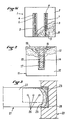
- FIG. 3 there is shown in longitudinal section a buttress of recessed beam reinforced according to the method of the present invention.
- a wooden beam 21 is embedded in a load-bearing wall 20.
- a first zone 22 of the beam is healthy and a second zone 23 located near the wall is degraded, for example by decay. There is a lack of wood at the end of the beam, at the level of the embedding.
- a reinforcing plate 25 has been introduced into a longitudinal groove not shown, but similar to those 4, 14 described previously with reference to FIGS. 1 and 2.
- the reinforcing plate extends in a part from the healthy zone 22, passes through the degraded zone 23 and protrudes from this second zone towards the outside, to the end of the beam as it originally appeared.
- a resin grout is then injected which fills all the voids, around the reinforcement plates in the groove, said plates thus being embedded in the resin grout, and between what remains of the beam and the wall 20, in the housing embedding 28.
- the excess resin permeates and strengthens the degraded or decomposed areas 23 of the wood, and gives them a resistance greater than their initial resistance.
- the plate 25 can be provided with fixing holes or dowels 26 for fixing and positioning.
- Figures 4a and 4b illustrate a variant of the method described with reference to Figure 3.
- the method of the invention is used to reconstruct a beam end.
- the end of a wooden beam 31 supported by this end in a wall 30 is degraded and the support must be restored.
- Two longitudinal grooves 34 are dug in the beam and reinforcing plates 35 pierced with holes 36 are introduced into the grooves.
- the reinforcement plates are here provided with bearing heels 40 at their lower part.
- the grooves start from a healthy zone 32 of the beam, crossing the degraded zone 33 and extend towards the support up to the end of the beam as it appeared before its degradation.
- a resin grout is injected into the grooves 34. It fills these grooves, permeates the degraded area 33 and replaces the missing material 38, here wood, at the end of the beam.
- a seal bottom 39 can be provided to limit resin overflows.
- the method of the invention can also be used to allow a beam to withstand forces for which it was not originally intended.
- This application of the process of the invention is illustrated in FIG. 5.
- a wooden beam 41 is cracked in the middle according to surfaces defined by oblique lines 42.
- props 43 After having taken up the deflection of the beam by means of props 43, one digs in the lower part of the beam one or more longitudinal grooves 44 in each of which a reinforcing plate 45 is drilled with holes 46.
- injection drilling 47, 48 which intersects the rupture cracks 42 in the beam 41, a resin-based product is injected into these drilling. In this way, the resin product travels through the cracks and restores the monolithism of the beam.
- the grooves are also filled with resin.
- the plate 51 is pierced with securing holes 56.
- the beam has been restored to its initial strength after hardening of the resin injected into the groove 54 around the metal plate.
- the metal plate It is easy to size the metal plate, because it was enough here to give it the same mechanical resistance as the wooden beam from the point of view of bending moments and sharp forces, the rest of the wooden beam being used here only for s opposing the buckling of the compressed part of the metal plate, above its neutral axis.
- the method of the present invention is particularly applicable to the reinforcement of building structures, for example in the context of rehabilitation, conversion or restoration of building operations.
Landscapes
- Engineering & Computer Science (AREA)
- Architecture (AREA)
- Chemical & Material Sciences (AREA)
- Chemical Kinetics & Catalysis (AREA)
- Electrochemistry (AREA)
- Mechanical Engineering (AREA)
- Civil Engineering (AREA)
- Structural Engineering (AREA)
- Rod-Shaped Construction Members (AREA)
Abstract
Description
La présente invention concerne un procédé de renforcement d'éléments de charpente ou de structures de bâtiment, notamment en bois, tels que des poutres.The present invention relates to a method of reinforcing structural elements or building structures, in particular of wood, such as beams.
On peut être amené à renforcer des poutres et éléments de charpente en bois pour différentes raisons:
- altération du bois par suite des intempéries ou de l'attaque par des larves d'insectes, des algues, des champignons, des micro-organisms (pourritures). Ces altérations touchent fréquemment par exemple les extrémités de poutres encastrées, à cause notamment de l'humidité qui peut régner autour de la poutre au niveau de l'encastrement par absence de ventilation;
- apparition de charges anormales pouvant entraîner la rupture de fibres : surcharge des planchers, modification de la géométrie des assemblages par suite de tassements des fondations, etc... .We can reinforce wooden beams and structural elements for different reasons:
- weathering of the wood due to bad weather or attack by insect larvae, algae, fungi, micro-organisms (rots). These alterations frequently affect for example the ends of embedded beams, in particular because of the humidity which can reign around the beam at the level of the embedding by absence of ventilation;
- appearance of abnormal loads which can lead to the breaking of fibers: overloading of floors, modification of the geometry of assemblies due to settlement of foundations, etc ....
Le brevet français no 2.170.498 de BOUWECONOMISCH EN TECHNOLOGHISCH ADVIESBUREAU décrit un procédé de renforcement de poutres en bois dans la région de leur appui par des tiges d'armature enfoncées dans des trous forés dans le bois et solidarisées au bois par une pâte durcissable à base de résine. Ce procédé présente plusieurs inconvénients : d'une part il est difficile de dimensionner les tiges d'armatures car on ne connaît pas toujours la direction et l'intensité des forces à reprendre dans une poutre dégradée, d'autre part ce procédé ne concerne que les renforcements de poutres au niveau de leurs appuis. Enfin, des tiges d'armature travaillent surtout en traction, et c'est la poutre dégradée qui doit fournir le complément de résistance mécanique nécessaire à la reprise des moments fléchissants et des efforts de compression.French Patent No. 2,170,498 of BOUWECONOMISCH IN TECHNOLOGHISCH ADVIESBUREAU discloses a method of building wooden beams in the region of their support by reinforcement rods embedded in holes drilled in the timber and secured to the timber by a curable paste resin-based. This process has several drawbacks: on the one hand, it is difficult to size the reinforcing rods because we do not always know the direction and intensity of the forces to be taken up in a degraded beam, on the other hand, this process only concerns beam reinforcements at their supports. Finally, reinforcing rods work especially in traction, and it is the degraded beam which must provide the additional mechanical resistance necessary for the resumption of bending moments and compression forces.
Un but de la présente invention est de proposer un procédé de renforcement d'élements de charpente ou de structures de bâtiment, notamment en bois, tels que des poutres, sans ajouter de pièces de renforcement structurelles à l'extérieur desdits éléments, et tout en préservant la forme et l'encombrement d'origine de ces éléments, ainsi que leur aspect dans la plupart des cas. Un autre but de la présente invention est que ledit renforcement soit facilement calculable, et qu'il soit possible en le mettant en oeuvre de renforcer un élément en bois tant au niveau de ses appuis qu'en d'autres endroits, voire sur toute sa longueur.An object of the present invention is to provide a method of reinforcing structural elements or building structures, in particular of wood, such as beams, without adding structural reinforcing parts to the exterior of said elements, and while preserving the original shape and size of these elements, as well as their appearance in most cases. Another object of the present invention is that said reinforcement is easily calculable, and that it is possible by implementing it to reinforce a wooden element both at the level of its supports and in other places, or even throughout its length.
Selon la présente invention, un procédé de renforcement d'éléments de charpente ou de structures de bâtiment, notamment en bois, tels que des poutres, comprend les étapes suivantes:
- creuser des cavités sensiblement planes dans les zones à renforcer de l'élément ;
- insérer dans lesdites cavités des plaques de renforcement ;
- remplir lesdites cavités d'un produit durcissable de remplissage à base de résine de façon à solidariser lesdits plaques à l'élément,
lesdites plaques de renforcement étant suffisamment résistantes et dimensionnées pour pourvoir restituer ou conférer à l'élément l'inertie souhaitée après solidarisation.According to the present invention, a method of reinforcing structural elements or building structures, in particular of wood, such as beams, comprises the following steps:
- dig substantially flat cavities in the areas to be reinforced of the element;
- inserting into said cavities reinforcement plates;
filling said cavities with a curable resin-based filling product so as to secure said plates to the element,
said reinforcing plates being sufficiently strong and dimensioned to provide restore or give the element the desired inertia after joining.
Les cavités sont par exemple des feuillures ou des rainures creusées dans le bois.The cavities are for example rebates or grooves dug in the wood.
Le produit à base de résine peut être une résine époxydique, un coulis ou un mortier de résine, adhérant fortement aussi bien sur le bois que sur le matériau des plaques de renforcement, lequel peut être du métal, du bois, une matière plastique, ou tout autre matériau suffisamment rigide et résistant. Les plaques peuvent également être de métal déployé.The resin product can be an epoxy resin, a grout or a resin mortar, which adheres strongly to both the wood and the material of the reinforcing plates, which can be metal, wood, plastic, or any other sufficiently rigid and resistant material. The plates can also be of expanded metal.
Selon un mode de réalisation avantageux de l'invention, la solidarisation des plaques de renforcement avec le coulis ou le mortier de résine peut être améliorée, soit en perforant ou en ajourant les plaques de renforcement, soit en les équipant de saillies ou de reliefs tels que des chevilles ou des tétons.According to an advantageous embodiment of the invention, the connection of the reinforcement plates with the grout or the resin mortar can be improved, either by perforating or perforating the reinforcement plates, or by equipping them with projections or reliefs such than ankles or nipples.
Toujours selon l'invention, si l'élément comporte des zones dégradées, les zones dégradées peuvent préalablement être régénérées par imprégnation par capillarité ou injection de produit à base de résines fluides, éventuellement solvantées, ou rechargées avec un mortier de résine semi-souple dont l'élasticité aura été ajustée en fonction de celle du bois.Still according to the invention, if the element comprises degraded areas, the degraded areas can be regenerated beforehand by impregnation by capillary action or injection of product based on fluid resins, possibly solvent-based, or recharged with a semi-flexible resin mortar, the elasticity will have been adjusted according to that of the wood.
D'autres caractéristiques et avantages de la présente invention apparaîtront mieux à la lecture de la description suivante donnée à titre d'exemples non limitatifs des formes possibles de réalisation de l'invention, en regard des dessins ci-joints et qui fera bien comprendre comment l'invention peut être réalisée.Other characteristics and advantages of the present invention will appear better on reading the following description given by way of nonlimiting examples of the possible embodiments of the invention, with reference to the attached drawings and which will make it clear how the invention can be realized.
Sur les dessins:
- les figures 1a à 1d sont des coupes transversales de principe illustrant différentes étapes du renforcement d'un élément selon un mode de réalisation du procédé de l'invention;
- la figure 2 est une coupe transversale de principe d'un élément renforcé selon un autre mode de réalisation du procédé de l'invention ;
- la figure 3 est une coupe longitudinale de principe d'un about pourri de poutre encastrée renforcé selon le procédé de l'invention ;
- la figure 4a est une coupe longitudinale de principe d'un autre about de poutre encastrée renforcé selon le procédé de l'invention;
- la figure 4b est une coupe transversale de principe de l'about de poutre de la figure 4a, selon la ligne XX;
- la figure 5 est une vue partielle de côté d'une poutre surchargée en cours de renforcement selon le procédé de l'invention;
- la figure 6 est une vue en perspective d'une poutre en bois à laquelle on a restitué sa résistance initiale sur toute sa longueur grâce au procédé.
- FIGS. 1a to 1d are cross-sections in principle illustrating different stages of the reinforcement of an element according to an embodiment of the method of the invention;
- Figure 2 is a cross section in principle of a reinforced element according to another embodiment of the method of the invention;
- Figure 3 is a longitudinal section in principle of a rotten butt end of a reinforced recessed beam according to the method of the invention;
- FIG. 4a is a longitudinal section in principle of another end of a reinforced embedded beam according to the method of the invention;
- Figure 4b is a cross section in principle of the beam end of Figure 4a, along line XX;
- Figure 5 is a partial side view of an overloaded beam being reinforced according to the method of the invention;
- FIG. 6 is a perspective view of a wooden beam to which its initial resistance has been restored over its entire length thanks to the process.
Sur la figure 1a, on a représenté une poutre 1 de section rectangulaire en coupe transversale. Une première zone 2 est saine, tandis qu'une deuxième zone 3 est dégradée par pourrissement. Les traits interrompus montrent la forme initiale de poutre. Sur la figure 1b, des cavités en forme de saignées 4 ont été creusées dans la poutre. Les saignées traversent la zone dégradée 3 et pénètrent dans la zone saine 2. La figure 1c illustre une phase ultérieure du renforcement de poutre: la zone dégradée 3 à été imprégnée de résine, et des plaques de renforcement longitudinales 5 ont été mises en place dans lesdites saignées 4. Les plaques de renforcement 5 sont percées de trous 6. Sur la figure 1d, le renforcement est terminé: on a injecté un coulis de résine 7 dans lesdites saignées 4 autour des plaques 5 , et la forme de la poutre a été reconstituée par un apport de matériau en 8, qui peut être un mortier de résine. Les trous 6 ont des dimensions telles qu'ils se sont remplis de coulis de résine lors de l'injection, ce qui améliore la solidarisation des plaques de renforcement avec le reste de la poutre 1.In Figure 1a, there is shown a
La figure 2 est une coupe transversale d'une poutre renforcée selon une autre variante du procédé de la présente invention. On reconnaît une poutre 11, une zone saine 12, une zone dégradée 13 régénérée par imprégnation de résine, une saignée 14, qui s'étend longitudinalement, et une plaque de renforcement 15 introduite dans ladite saignée. Cette fois, la plaque de renforcement 15 est munie de tétons ou chevilles 16 de solidarisation pour améliorer la solidarisation de ladite plaque au reste de la poutre 11. Lesdites chevilles permettent également de positionner la plaque de renforcement 15 dans la saignée avant l'injection et la prise du coulis de résine.Figure 2 is a cross section of a reinforced beam according to another variant of the method of the present invention. We recognize a
Sur la figure 3, on a représenté en coupe longitudinale un about de poutre encastrée renforcé selon le procédé de la présente invention. Une poutre en bois 21 est encastrée dans un mur porteur 20. Une première zone 22 de la poutre est saine et une deuxième zone 23 située près du mur est dégradée, par exemple par pourriture. Il manque du bois au bout de la poutre, au niveau de l'encastrement. Selon le procédé de l'invention, on a introduit une plaque de renforcement 25 dans une saignée longitudinale non représentée, mais similaire à celles 4, 14 décrites précédemment en références aux figures 1 et 2. La plaque de renforcement s'étend dans une partie de la zone saine 22, passe par la zone dégradée 23 et dépasse de cette deuxième zone vers l'extérieur, jusqu'au bout de la poutre telle qu'elle se présentait à l'origine. On injecte ensuite un coulis de résine qui remplit tous les vides, autour des plaques de renforcement dans la saignée, lesdites plaques se trouvant ainsi noyées dans le coulis de résine, et entre ce qui reste de la poutre et le mur 20, dans le logement d'encastrement 28. De plus, l'excédent de résine imprègne et renforce les zones dégradées ou décomposées 23 du bois, et leur confère une résistance supérieure à leur résistance initiale. Comme précédemment, la plaque 25 peut être munie de trous de solidarisation ou de chevilles 26 de solidarisation et de positionnement.In Figure 3, there is shown in longitudinal section a buttress of recessed beam reinforced according to the method of the present invention. A
Les figures 4a et 4b illustrent une variante du procédé décrit en référence à la figure 3. Cette fois, le procédé de l'invention est utilisé pour reconstituer un about de poutre. L'extrémité d'une poutre en bois 31 appuyée par cette extrémité dans un mur 30 est dégradée et il faut reconstituer l'appui. Deux saignées longitudinales 34 sont creusées dans la poutre et des plaques de renforcement 35 percées de trous 36 sont introduites dans les saignées. Les plaques de renforcement sont ici munies de talons d'appui 40 à leur partie inférieure. Les saignées partent d'une zone saine 32 de la poutre, traversant la zone dégradée 33 et se prolongent vers l'appui jusqu'à l'extrémité de la poutre telle qu'elle se présentait avant sa dégradation. Comme précédemment, un coulis de résine est injecté dans les saignées 34. Il remplit ces saignées, imprègne la zone dégradée 33 et remplace la matière manquante 38, ici du bois, à l'extrémité de la poutre. Un fond de joint 39 peut être prévu pour limiter les débordements de résine.Figures 4a and 4b illustrate a variant of the method described with reference to Figure 3. This time, the method of the invention is used to reconstruct a beam end. The end of a
Le procédé de l'invention peut également être utilisé pour permettre à une poutre de résister à des efforts pour laquelle elle n'avait pas été prévue à l'origine. Cette application du procédé de l'invention est illustré sur la figure 5. A la suite d'une surcharge engendrant un moment fléchissant excessif, une poutre 41 en bois est fissurée en son milieu selon des surfaces définies par des lignes obliques 42. Selon l'invention, après avoir repris la flèche de la poutre au moyen d'étançons 43, on creuse dans la partie inférieure de la poutre une ou plusieurs saignées longitudinales 44 dans chacune desquelles on glisse une plaque de renforcement 45 percée de trous 46. Aprés avoir réalisé des forages d'injection 47, 48 qui recoupent les fissures de rupture 42 dans la poutre 41, on injecte un produit à base de résine dans ces forages. De cette façon, le produit à base de résine chemine dans les fissures et rétabli le monolithisme de la poutre. Comme précédemment, les saignées sont elles aussi remplies de résine.The method of the invention can also be used to allow a beam to withstand forces for which it was not originally intended. This application of the process of the invention is illustrated in FIG. 5. Following an overload causing an excessive bending moment, a
Dans le dernier exemple, illustré sur la figure 6, une poutre en bois 51 de 8 mètres de long et de 0,4 x 0,4 m2 de section, encastrée en ses extrémités sur une profondeur de 0,40 m, a été renforcée sur toute sa longueur au moyen d'une plaque métallique 55 de 15 mm d'épaisseur insérée dans une saignée 54 de 20 mm de large partant du dessus de la poutre et s'arrêtant à 50 mm du bas de la poutre. La plaque 51 est percée de trous de solidarisation 56. Dans cet exemple, on a redonné à la poutre sa résistance initiale après durcissement de la résine injectée dans la saignée 54 autour de la plaque métallique. Il est facile de dimensionner la plaque métallique, car il suffisait ici de lui donner la même résistance mécanique que la poutre en bois du point du vue des moments fléchissants et efforts tranchants, le reste de la poutre en bois ne servant ici qu'a s'opposer au flambage de la partie comprimée de la plaque métallique, au-dessus de son axe neutre.In the last example, illustrated in Figure 6, a
Le procédé de la présente invention s'applique notamment au renforcement des structures de bâtiments, par exemple dans le cadre d'opérations de réhabilitation, de reconversion ou de restauration de bâtiment.The method of the present invention is particularly applicable to the reinforcement of building structures, for example in the context of rehabilitation, conversion or restoration of building operations.
Claims (9)
- creuser des cavités en forme de feuillures ou de rainures (4, 14, 24, 34, 44, 54) dans les zones à renforcer de l'élément ;
- insérer dans lesdites cavités des plaques de renforcement (5, 15, 25, 35, 45, 55) percées de trous (6, 26, 36, 46, 56);
- remplir simultanément lesdites cavités (4, 14, 24, 34, 44, 54) et lesdits trous (6, 26, 36, 46, 56) d'un produit durcissable de remplissage à base de résine de façon à solidariser lesdites plaques à l'élément, lesdits trous permettant une meilleure solidarisation desdites plaques audit produit après durcissement,
lesdites plaques de renforcement étant suffisamment résistantes et dimensionnées pour pouvoir restituer ou conférer audit élément l'inertie souhaitée après durcissement.1. Method for reinforcing a building structure element (1, 11, 21, 31, 41, 51), in particular a wooden element having degraded parts (3, 13, 23, 33), characterized in that '' it includes the following stages:
- dig cavities in the form of rebates or grooves (4, 14, 24, 34, 44, 54) in the areas to be reinforced of the element;
- inserting into said cavities reinforcing plates (5, 15, 25, 35, 45, 55) pierced with holes (6, 26, 36, 46, 56);
- simultaneously filling said cavities (4, 14, 24, 34, 44, 54) and said holes (6, 26, 36, 46, 56) with a curable resin-based filling product so as to secure said plates to the element, said holes allowing better attachment of said plates to said product after hardening,
said reinforcing plates being sufficiently resistant and dimensioned to be able to restore or impart to said element the desired inertia after hardening.
Applications Claiming Priority (2)
| Application Number | Priority Date | Filing Date | Title |
|---|---|---|---|
| FR8615333A FR2606057B1 (en) | 1986-11-04 | 1986-11-04 | REINFORCEMENT OF STRUCTURAL ELEMENTS BY INSERTING HIGH-STRENGTH PLATES |
| FR8615333 | 1986-11-04 |
Publications (2)
| Publication Number | Publication Date |
|---|---|
| EP0269497A1 true EP0269497A1 (en) | 1988-06-01 |
| EP0269497B1 EP0269497B1 (en) | 1991-06-12 |
Family
ID=9340498
Family Applications (1)
| Application Number | Title | Priority Date | Filing Date |
|---|---|---|---|
| EP87402468A Expired - Lifetime EP0269497B1 (en) | 1986-11-04 | 1987-11-03 | Reinforcement of supporting structure elements by inserting highly resistant plates |
Country Status (4)
| Country | Link |
|---|---|
| EP (1) | EP0269497B1 (en) |
| DE (1) | DE3770774D1 (en) |
| ES (1) | ES2025188B3 (en) |
| FR (1) | FR2606057B1 (en) |
Cited By (8)
| Publication number | Priority date | Publication date | Assignee | Title |
|---|---|---|---|---|
| EP0518246A2 (en) * | 1991-06-14 | 1992-12-16 | Berthold Fries | Method for production of wooden hollow beams and forms of this beam obtained by this method |
| FR2691739A1 (en) * | 1992-06-02 | 1993-12-03 | Renofors France | Repairing corrosion-deteriorated reinforced beam - by cutting away deteriorated portion and making perpendicular channel in beam to receive inverted T=shaped reinforcing elements, e.g. of fibre-reinforced compsn. material |
| FR2700805A1 (en) * | 1993-01-27 | 1994-07-29 | Ind Entreprise | Process for reinforcing a damaged beam and beam thus obtained |
| EP0674060A1 (en) * | 1994-03-04 | 1995-09-27 | Wilhelm Modersohn GmbH & Co KG Verankerungstechnik | Reinforcement for masonry |
| WO1999004116A1 (en) * | 1997-07-15 | 1999-01-28 | Bilfinger + Berger Bauaktiengesellschaft | Component |
| EP1437459A1 (en) * | 2001-09-25 | 2004-07-14 | Structural Quality Assurance, Inc. | Reinforcement material and reinforcement structure of structure and method of designing reinforcement material |
| FR3044687A1 (en) * | 2015-12-07 | 2017-06-09 | M Lefevre | METHOD FOR REINFORCING A BUILDING ELEMENT BY ASSEMBLING REINFORCING MODULES AND AT LEAST ONE PLATE CONNECTED TO THE REINFORCING MODULES |
| EP3591130A1 (en) | 2018-07-04 | 2020-01-08 | Klasch Spezial- Bauartikel GmbH | Ceiling construction |
Families Citing this family (1)
| Publication number | Priority date | Publication date | Assignee | Title |
|---|---|---|---|---|
| FR2728293A1 (en) * | 1994-12-14 | 1996-06-21 | Brochard Francois Xavier | Reinforcement for timber frames of building |
Citations (5)
| Publication number | Priority date | Publication date | Assignee | Title |
|---|---|---|---|---|
| FR2170498A5 (en) * | 1971-12-20 | 1973-09-14 | Bouweconomisch Technolog | |
| DE2451639A1 (en) * | 1974-10-30 | 1976-05-06 | Hans Binker | Increasing strength of woods and building materials - rods of glass fibre reinforced material inserted into cut notches |
| FR2400096A1 (en) * | 1977-08-10 | 1979-03-09 | Freyssinet Int Stup | Reinforced concrete with steel plate bonded to tensile face - has perforated plate preventing trapping of air bubble in adhesive |
| GB2134965A (en) * | 1983-01-24 | 1984-08-22 | Dzus Fastener Europe | Quarter turn fastener |
| GB2150969A (en) * | 1983-12-06 | 1985-07-10 | Dinardo And Partners | Restoring and strengthening of timber components |
Family Cites Families (1)
| Publication number | Priority date | Publication date | Assignee | Title |
|---|---|---|---|---|
| GB2134956A (en) * | 1983-02-10 | 1984-08-22 | Rickards Timber Treatment Limi | Upgrading or restoring a timber beam |
-
1986
- 1986-11-04 FR FR8615333A patent/FR2606057B1/en not_active Expired - Lifetime
-
1987
- 1987-11-03 EP EP87402468A patent/EP0269497B1/en not_active Expired - Lifetime
- 1987-11-03 ES ES87402468T patent/ES2025188B3/en not_active Expired - Lifetime
- 1987-11-03 DE DE8787402468T patent/DE3770774D1/en not_active Expired - Lifetime
Patent Citations (5)
| Publication number | Priority date | Publication date | Assignee | Title |
|---|---|---|---|---|
| FR2170498A5 (en) * | 1971-12-20 | 1973-09-14 | Bouweconomisch Technolog | |
| DE2451639A1 (en) * | 1974-10-30 | 1976-05-06 | Hans Binker | Increasing strength of woods and building materials - rods of glass fibre reinforced material inserted into cut notches |
| FR2400096A1 (en) * | 1977-08-10 | 1979-03-09 | Freyssinet Int Stup | Reinforced concrete with steel plate bonded to tensile face - has perforated plate preventing trapping of air bubble in adhesive |
| GB2134965A (en) * | 1983-01-24 | 1984-08-22 | Dzus Fastener Europe | Quarter turn fastener |
| GB2150969A (en) * | 1983-12-06 | 1985-07-10 | Dinardo And Partners | Restoring and strengthening of timber components |
Cited By (10)
| Publication number | Priority date | Publication date | Assignee | Title |
|---|---|---|---|---|
| EP0518246A2 (en) * | 1991-06-14 | 1992-12-16 | Berthold Fries | Method for production of wooden hollow beams and forms of this beam obtained by this method |
| EP0518246A3 (en) * | 1991-06-14 | 1993-05-19 | Berthold Fries | Method for production of wooden hollow beams and forms of this beam obtained by this method |
| FR2691739A1 (en) * | 1992-06-02 | 1993-12-03 | Renofors France | Repairing corrosion-deteriorated reinforced beam - by cutting away deteriorated portion and making perpendicular channel in beam to receive inverted T=shaped reinforcing elements, e.g. of fibre-reinforced compsn. material |
| FR2700805A1 (en) * | 1993-01-27 | 1994-07-29 | Ind Entreprise | Process for reinforcing a damaged beam and beam thus obtained |
| EP0674060A1 (en) * | 1994-03-04 | 1995-09-27 | Wilhelm Modersohn GmbH & Co KG Verankerungstechnik | Reinforcement for masonry |
| WO1999004116A1 (en) * | 1997-07-15 | 1999-01-28 | Bilfinger + Berger Bauaktiengesellschaft | Component |
| EP1437459A1 (en) * | 2001-09-25 | 2004-07-14 | Structural Quality Assurance, Inc. | Reinforcement material and reinforcement structure of structure and method of designing reinforcement material |
| EP1437459A4 (en) * | 2001-09-25 | 2005-07-06 | Structural Quality Assurance I | Reinforcement material and reinforcement structure of structure and method of designing reinforcement material |
| FR3044687A1 (en) * | 2015-12-07 | 2017-06-09 | M Lefevre | METHOD FOR REINFORCING A BUILDING ELEMENT BY ASSEMBLING REINFORCING MODULES AND AT LEAST ONE PLATE CONNECTED TO THE REINFORCING MODULES |
| EP3591130A1 (en) | 2018-07-04 | 2020-01-08 | Klasch Spezial- Bauartikel GmbH | Ceiling construction |
Also Published As
| Publication number | Publication date |
|---|---|
| EP0269497B1 (en) | 1991-06-12 |
| FR2606057B1 (en) | 1990-10-12 |
| FR2606057A1 (en) | 1988-05-06 |
| ES2025188B3 (en) | 1992-03-16 |
| DE3770774D1 (en) | 1991-07-18 |
Similar Documents
| Publication | Publication Date | Title |
|---|---|---|
| US4644722A (en) | Repairing utility poles | |
| FR2611778A1 (en) | FLOOR WITH COLLABORATION WOOD-CONCRETE | |
| EP0269497B1 (en) | Reinforcement of supporting structure elements by inserting highly resistant plates | |
| FR2510163A1 (en) | Reinforcing wooden beam - using resin concrete tied to beam top increasing design load | |
| FR3009318A1 (en) | METHOD OF BUILDING A WORK IN PREFABRICATED CONCRETE ELEMENTS AND ASSOCIATED WORK | |
| FR3002956A1 (en) | PRECONTRATED MOLDED WALL AND METHOD OF MAKING SUCH A WALL | |
| CA2636921A1 (en) | Process for reinforcing a building structure, and structure thus reinforced | |
| EP0244890B1 (en) | Process for producing hollow structures such as ducts, silos, or shelters, and structures obtained by this process | |
| WO2010140277A1 (en) | Woody material joint structure and joint member for use therein | |
| EP2868829B1 (en) | Method for reinforcing a timber construction element by assembling a reinforcement module placed under post-tension | |
| EP0483158B1 (en) | Anchoring and bedding method by using digging cross stays | |
| JP6543010B1 (en) | Bonding structure of wooden members | |
| US3900541A (en) | Method of restoring a wooden beam | |
| EP2868841A1 (en) | Method for reinforcing a timber construction element by a reinforcement module | |
| JP2004092058A (en) | Structure and method for joining composition member for building | |
| FR2728293A1 (en) | Reinforcement for timber frames of building | |
| JP2009185549A (en) | Method of reinforcing structural skeleton and structural skeleton | |
| CA3029277A1 (en) | Uhpc post - composite post | |
| FR2760478A1 (en) | BEAM-TYPE CONSTRUCTION ELEMENT | |
| JP2021001450A (en) | Wall balustrade reinforcement method and reinforcement structure | |
| FR2596443A1 (en) | METHOD FOR RESTORING A WOODEN STRUCTURE ELEMENT | |
| EP2868828A1 (en) | Method for reinforcing a construction element by assembling reinforcing modules and at least one termination element | |
| EP3800304A1 (en) | Reinforcing rod for a reinforced concrete structural element, assembly of structural elements, and method for manufacturing an assembly of structural elements | |
| EP3800303A1 (en) | Rod for attaching, assembly of structural and non-structural elements by means of such a rod, and method for manufacturing such an assembly | |
| FR2892440A1 (en) | Construction element e.g. brick masonry structure, reinforcing method, involves inserting grout with base of hydraulic cement and basalt after drilling inside element, where basalt is powdery or fibrous mixed with hydraulic cement |
Legal Events
| Date | Code | Title | Description |
|---|---|---|---|
| PUAI | Public reference made under article 153(3) epc to a published international application that has entered the european phase |
Free format text: ORIGINAL CODE: 0009012 |
|
| AK | Designated contracting states |
Kind code of ref document: A1 Designated state(s): BE DE ES GB IT |
|
| 17P | Request for examination filed |
Effective date: 19881130 |
|
| 17Q | First examination report despatched |
Effective date: 19900309 |
|
| GRAA | (expected) grant |
Free format text: ORIGINAL CODE: 0009210 |
|
| AK | Designated contracting states |
Kind code of ref document: B1 Designated state(s): BE DE ES GB IT |
|
| PG25 | Lapsed in a contracting state [announced via postgrant information from national office to epo] |
Ref country code: IT Free format text: LAPSE BECAUSE OF FAILURE TO SUBMIT A TRANSLATION OF THE DESCRIPTION OR TO PAY THE FEE WITHIN THE PRE;WARNING: LAPSES OF ITALIAN PATENTS WITH EFFECTIVE DATE BEFORE 2007 MAY HAVE OCCURRED AT ANY TIME BEFORE 2007. THE CORRECT EFFECTIVE DATE MAY BE DIFFERENT FROM THE ONE RECORDED.SCRIBED TIME-LIMIT Effective date: 19910612 |
|
| REF | Corresponds to: |
Ref document number: 3770774 Country of ref document: DE Date of ref document: 19910718 |
|
| GBT | Gb: translation of ep patent filed (gb section 77(6)(a)/1977) | ||
| REG | Reference to a national code |
Ref country code: ES Ref legal event code: FG2A Ref document number: 2025188 Country of ref document: ES Kind code of ref document: B3 |
|
| PLBE | No opposition filed within time limit |
Free format text: ORIGINAL CODE: 0009261 |
|
| STAA | Information on the status of an ep patent application or granted ep patent |
Free format text: STATUS: NO OPPOSITION FILED WITHIN TIME LIMIT |
|
| 26N | No opposition filed | ||
| PGFP | Annual fee paid to national office [announced via postgrant information from national office to epo] |
Ref country code: ES Payment date: 19931116 Year of fee payment: 7 |
|
| PGFP | Annual fee paid to national office [announced via postgrant information from national office to epo] |
Ref country code: BE Payment date: 19931130 Year of fee payment: 7 |
|
| PGFP | Annual fee paid to national office [announced via postgrant information from national office to epo] |
Ref country code: GB Payment date: 19941102 Year of fee payment: 8 |
|
| PG25 | Lapsed in a contracting state [announced via postgrant information from national office to epo] |
Ref country code: ES Free format text: LAPSE BECAUSE OF THE APPLICANT RENOUNCES Effective date: 19941104 |
|
| PG25 | Lapsed in a contracting state [announced via postgrant information from national office to epo] |
Ref country code: BE Effective date: 19941130 |
|
| PGFP | Annual fee paid to national office [announced via postgrant information from national office to epo] |
Ref country code: DE Payment date: 19950104 Year of fee payment: 8 |
|
| BERE | Be: lapsed |
Owner name: WOLF PHILIPPE Effective date: 19941130 Owner name: ROBERT CLAUDE Effective date: 19941130 Owner name: PACHET ANDRE Effective date: 19941130 |
|
| PG25 | Lapsed in a contracting state [announced via postgrant information from national office to epo] |
Ref country code: GB Effective date: 19951103 |
|
| GBPC | Gb: european patent ceased through non-payment of renewal fee |
Effective date: 19951103 |
|
| PG25 | Lapsed in a contracting state [announced via postgrant information from national office to epo] |
Ref country code: DE Effective date: 19960801 |
|
| REG | Reference to a national code |
Ref country code: ES Ref legal event code: FD2A Effective date: 20010402 |