EP0269432B2 - Analysiervorrichtung für eine Flüssigkeit innerhalb einer Rohrleitung - Google Patents
Analysiervorrichtung für eine Flüssigkeit innerhalb einer Rohrleitung Download PDFInfo
- Publication number
- EP0269432B2 EP0269432B2 EP87310400A EP87310400A EP0269432B2 EP 0269432 B2 EP0269432 B2 EP 0269432B2 EP 87310400 A EP87310400 A EP 87310400A EP 87310400 A EP87310400 A EP 87310400A EP 0269432 B2 EP0269432 B2 EP 0269432B2
- Authority
- EP
- European Patent Office
- Prior art keywords
- radiation
- pipe
- analyzer
- fluid
- beryllium
- Prior art date
- Legal status (The legal status is an assumption and is not a legal conclusion. Google has not performed a legal analysis and makes no representation as to the accuracy of the status listed.)
- Expired - Lifetime
Links
Images


Classifications
-
- G—PHYSICS
- G01—MEASURING; TESTING
- G01N—INVESTIGATING OR ANALYSING MATERIALS BY DETERMINING THEIR CHEMICAL OR PHYSICAL PROPERTIES
- G01N23/00—Investigating or analysing materials by the use of wave or particle radiation, e.g. X-rays or neutrons, not covered by groups G01N3/00 – G01N17/00, G01N21/00 or G01N22/00
- G01N23/02—Investigating or analysing materials by the use of wave or particle radiation, e.g. X-rays or neutrons, not covered by groups G01N3/00 – G01N17/00, G01N21/00 or G01N22/00 by transmitting the radiation through the material
- G01N23/06—Investigating or analysing materials by the use of wave or particle radiation, e.g. X-rays or neutrons, not covered by groups G01N3/00 – G01N17/00, G01N21/00 or G01N22/00 by transmitting the radiation through the material and measuring the absorption
- G01N23/12—Investigating or analysing materials by the use of wave or particle radiation, e.g. X-rays or neutrons, not covered by groups G01N3/00 – G01N17/00, G01N21/00 or G01N22/00 by transmitting the radiation through the material and measuring the absorption the material being a flowing fluid or a flowing granular solid
-
- G—PHYSICS
- G01—MEASURING; TESTING
- G01N—INVESTIGATING OR ANALYSING MATERIALS BY DETERMINING THEIR CHEMICAL OR PHYSICAL PROPERTIES
- G01N23/00—Investigating or analysing materials by the use of wave or particle radiation, e.g. X-rays or neutrons, not covered by groups G01N3/00 – G01N17/00, G01N21/00 or G01N22/00
- G01N23/02—Investigating or analysing materials by the use of wave or particle radiation, e.g. X-rays or neutrons, not covered by groups G01N3/00 – G01N17/00, G01N21/00 or G01N22/00 by transmitting the radiation through the material
- G01N23/06—Investigating or analysing materials by the use of wave or particle radiation, e.g. X-rays or neutrons, not covered by groups G01N3/00 – G01N17/00, G01N21/00 or G01N22/00 by transmitting the radiation through the material and measuring the absorption
- G01N23/083—Investigating or analysing materials by the use of wave or particle radiation, e.g. X-rays or neutrons, not covered by groups G01N3/00 – G01N17/00, G01N21/00 or G01N22/00 by transmitting the radiation through the material and measuring the absorption the radiation being X-rays
Definitions
- This invention relates to an analyzer for fluid flowing through piping, and in particular but not exclusively, it relates to an analyzer which employs radiation to analyze the components of the fluid output of an oil well as it flows within piping.
- Figure 1 is a schematic diagram showing a conventional radiation analyzer for fluid within a pipe.
- element number 1 is a source of radiation such as X-rays or gamma rays
- element number 2 is a pipe which is disposed below the radiation source 1
- element number 3 is a fluid to be analyzed which is flowing through the pipe 2
- element number 4 is a radiation detector which detects the radiation which is transmitted through the fluid 3 from the radiation source 1
- element number 5 is a signal processing and calculating device which processes the signals from the radiation detector4 and produces an outputsignal corresponding to some physical quantity of the fluid
- element number 6 is a dome-shaped radiation transmission window which forms a part of the pipe 2 and is made of a material which easily transmits radiation.
- the radiation transmission window 6 is joined to the pipe 2 by brazing in a manner such that the fluid 3 flowing through the pipe 2 can not leak out.
- the attenuation of radiation such as X-rays or gamma rays in a substance is expressed by the following equation. wherein lo is the intensity of the incident radiation, ⁇ is the mass absorption coefficient with respect to radiation of the substance being measured, p is the specific gravity of the substance, to is the thickness of the substance through which the radiation passes, and I is the intensity of the radiation after passing through the thickness to.
- the fluid 3 of Figure 1 comprises a first substance and a second substance and the specific gravities of the two substances are respectively ⁇ 1 and ⁇ 2 , the mass absorption coefficients with respect to the radiation are respectively ⁇ 1 and p 2 , the component proportions are respectively k1 and k2, the wall thickness of the pipe 2 is d, its specific gravity is p w ,its mass absorption coefficient is Rw, and the length of the path of radiation passing through the fluid 3 is t, then the following relationships hold. t, d, ⁇ w , ⁇ 1 , ⁇ 2 , ⁇ w , ⁇ 1 , and p 2 are known in advance, and the incident radiation intensity 1 0 can be measured in advance.
- the proportions of the two components are not known, if the intensity I of radiation passing through the substance is measured, the values of k1 and k2 can be found from Equations (2) and (3), and the proportion of the components can be found.
- the intensity of the radiation after it passes through the fluid 3 can be measured by the radiation detector 4, and the values of k1 and k2 can be determined by the signal processing and calculating device 5 on the basis of Equations (2) and (3).
- the two components of the fluid 3 being measured are substances like water or oil which comprise light elements such as C, H, and O
- it is necessary to use radiation having a low photon energy For example, it is necessary to use radiation with a photon energy of at most 60 keV.
- a thin sheet of beryllium which has a low atomic number, is used as the radiation transmission window 6.
- the pipe 2 itself is commonly made of iron or steel, and since it is difficult to weld beryllium to these substances, the window 6 is usually secured to the pipe 2 by brazing.
- beryllium is not a hard material, if foreign objects such as sand are present in the fluid within the pipe 2, a window made of beryllium will undergo wear. Such wear affects the absorption of radiation by the window 6 and introduces errors into the measurements. In addition, over time, this wear can form holes in the window 6, resultina in fluid leaks.
- an object of the present invention to provide an analyzer for a fluid within a pipe which has a radiation transmission window with high resistance to pressure.
- An analyzer for fluids in accordance with the present invention has a tubular radiation transmission window which is coaxially disposed between two sections of the pipe which carries the fluid to be analyzed.
- the radiation transmission window comprises a beryllium tube and a tubular guard which fits tightly around the beryllium tube and has a higher stiffness than the beryllium. tube
- the tubular guard has two diametrically-opposed through holes formed therein through which radiation can pass.
- a radiation source is disposed on one side of the pipe so that the radiation generated thereby will enter the fluid via one of the through holes and exit through the other through hold.
- a radiation detector is disposed on the other side of the pipe and measures the intensity of the radiation which exists from the radiation transmission window.
- a signal processing and calculating device processes the signals from the radiation detector and produces an output signal corresponding to the physical property of the fluid being analyzed.
- the tubular guard resists the pressure of the fluid within the pipe so that the stresses within the beryllium tube are low, and the beryllium tube need be only thick enough to resist the pressure in the vicinity of the through holes.
- the pipe sections have flanges formed on the ends thereof, and the tubular guard has corresponding flanges formed on its ends which abut against and are secured to the flanges of the pipe sections by bolts.
- a leakproof joint is formed between the radiation transmission window and the pipe sections by means of O-rings which are disposed between the end surfaces of the beryllium tube and the end surfaces of the pipe sections.
- the radiation transmission window may be further equipped with a ceramic coating which is formed on the inner surface of the beryllium tube.
- the ceramic coating is preferably made of a substance comprising light atoms such as alumina, silicon carbide, MgO, silicon dioxide, and diamond.
- a source of gamma rays or X-rays is employed as a radiation source, but various other forms of radiation may also be used.
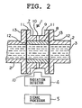
- FIG. 1 is a cross-sectional view of a first embodiment.
- a pipe 2 which carries a fluid 3 to be analyzed is divided into two coaxial sections which are separated by a radiation transmission window 7 which is coaxially disposed therebetween.
- the radiation transmission window 7 comprises a beryllium tube 8 and a tubular guard 9 which is made of steel and which fits tightly around the beryllium tube 8.
- Two diametrically-opposed through holes 10 are formed in the guard 9 at approximately its center, the inner ends of the through holes 10 opening onto the outer surface of the beryllium tube 8.
- Two flanges 11 are formed on opposite ends of the guard 9. These flanges 11 confront corresponding flanges 13 formed on the ends of two coaxial sections of the pipe 2.
- Two O-rings 12 are disposed between the end surfaces of the beryllium tube 8 and the flanges 13. The flanges 11 of the guard 9 are secured to the corresponding flanges 13 of the pipe section by unillustrated bolts.
- the radiation which passes through the fluid 3 being analyzed is detected by the radiation detector 4, and the signal processing and calculating device 5 processes the signals from the radiation detector4 and calculates the proportions of the components of the fluid 3 in the same manner as for the conventional apparatus of Figure 1.
- the pressure of the fluid 3 acting on the beryllium tube 8 is withstood by the guard 9. Therefore, even when the fluid pressure within the pipe 2 is high, only a very small stress is induced in the beryllium tube 8.
- the thickness of the beryllium tube 8 need only be large enough for the beryllium tube 8 to withstand the stresses in the vicinity of the through holes 10 in the tubular guard 9.
- the necessary thickness of the beryllium tube 8 is therefore roughly the same as the necessary thickness of the beryllium window 6 of the conventional apparatus of Figure 1. Therefore, the attentuation of radiation passing through the beryllium tube 8 is almost the same as that for the beryllium window 6 of Figure 1.
- the radiation transmission window 7 of the present invention can be mounted on a pipe 2 far more easily than a conventional radiation transmission window 6 which must be connected by brazing, particularly when the beryllium tube 8 is thick.
- the radiation transmission window 7 has a simple shape, it is highly reliable and has good pressure resistance.
- the present inventors manufactured a radiation transmission window 7 like that illustrated in Figure 2 with a beryllium tube 8 having an outer diameter of 7cm, an inner diameter of 5cm, and a length of 10cm.
- the radius of the through holes 10 was 2.5cm.
- a pressure of 700 kg per square cm was then applied to the inside of the window 7. There was no leakage or damage of any kind.
- the tubular guard 9 is made of steel, but it can be made of iron or other material to provide a higher stiffness than the beryllium tube. Furthermore, the lengths of the beryllium tube 8 and the tubular guard 9 are shown as being the same, but it is also possible for the beryllium tube 8 to be shorter than the tubular guard 9 and for the O-rings 12 to be disposed inside the ends of the tubular guard 9.
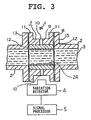
- FIG. 3 is a cross-sectional view of a second embodiment of an analyzer in accordance with the present invention.
- This embodiment differs from the first embodiment in that itfurthercomprises a thin alumina ceramic coating 24 which is applied to the inner surface of a beryllium tube 8.
- the beryllium tube 8 is 2cm thick, while the alumina ceramic coating 24 is 100 microns thick.
- the coating 24 can be applied to the beryllium tube 8 by plasma spray coating or by vacuum deposition to obtain a uniform, dense coating.
- An alumina ceramic coating with a thickness of 100 microns produces only 10% attenuation of X-rays with an energy of 20 keV, so the intensity of the radiation which enters the radiation detector 4 is fully adequate for measurement purposes.
- As alumina is very hard, the coating 24 protects the beryllium tube 8 from wear, and the wear resistance of the radiation transmission window 7 is greatly increased.
- the structure and operation of this embodiment are otherwise the same as for the embodiment of Figure 2.
- the present inventors performed a wear resistance test. 5% by volume of sand having a particle diameter of 1 mm was mixed with oil, and the mixture was sprayed at an angle of 65° at a speed of 1.9 meters per second for 700 hours against a beryllium plate which was coated with an alumina ceramic having a thickness of 100 microns. After the spraying, the coating was inspected for damage. No change of any kind was observed in the coating.
- the thickness of the alumina ceramic coating 24 is 100 microns, but the thickness can be varied in accordance with the circumstances of use.
- the wear resistance of the coating can be increased by increasing its thickness, while the transmission of radiation by the coating can be increased by decreasing its thickness.
- Various other substances besides an alumina ceramic can be used to form a protective coating on the inner surface of a beryllium tube.
- Silicon carbide, MgO, Si02, and other ceramics which are made of light elements are suitable.
- a diamond coating can also be employed. Such a coating can be applied by plasma chemical vapor deposition. A diamond coating not only provides protection against wear but also has excellent corrosion resistance.
- a ceramic such as zirconia (Zr0 2 ) which comprises heavy elements is used to form a ceramic coating, the transmission of radiation by the coating decreases. Therefore, it is preferable to employ a ceramic which is composed of light elements.
- Figure 4 is a graph of the transmission of three types of ceramic coatings with respect to 20 keV X-rays or gamma rays as a function of coating thickness. From this graph, it can be seen that a diamond coating absorbs substantially no X-rays or gamma rays even if its thickness reaches 1 mm. Furthermore, a silicon carbide film has acceptable transmission even up to a coating thickness of 100 microns.
- an analyzer was in the form of a component analyzer for analyzing two components of a fluid.
- the apparatus of the present invention can be employed as various other types of measuring devices, such as a device for measuring the density of a fluid or the amount of impurities in a fluid.
- a device for measuring the density of a fluid or the amount of impurities in a fluid instead of employing transmitted radiation, it is possible for the present invention to employ backscattered radiation or excited X-rays.
Landscapes
- Health & Medical Sciences (AREA)
- General Health & Medical Sciences (AREA)
- Life Sciences & Earth Sciences (AREA)
- Chemical & Material Sciences (AREA)
- Analytical Chemistry (AREA)
- Biochemistry (AREA)
- Physics & Mathematics (AREA)
- General Physics & Mathematics (AREA)
- Immunology (AREA)
- Pathology (AREA)
- Toxicology (AREA)
- Analysing Materials By The Use Of Radiation (AREA)
- Sampling And Sample Adjustment (AREA)
Claims (9)
dadurch gekennzeichnet,
gekennzeichnet durch eine Dichtungseinrichtung (12) um eine leckdichte Verbindung zwischen dem Strahlungsdurchgangsfenster und den Rohrabschnitten zu bilden, wobei die Dichtungseinrichtung (12) zwei O-Ringe (12) aufweist, von denen jeder zwischen der einen der stirnseitigen Oberflächen des Berylliumrohres und der stirnseitigen Oberfläche des angrenzenden Rohrabschnittes angeordnet ist.
wobei das Berylliumrohr kürzer als das rohrförmige Schutzteil ist, beide Enden des Berylliumrohres innerhalb der Enden des rohrförmigen Schutzteiles liegen und die O-Ringe innerhalb der Enden des rohrförmigen Schutzteiles zwischen den Enden des Berylliumrohres und den Enden der angrenzenden Rohrabschnitte angeordnet sind.
wobei eine Beschichtung (24) aus einer Substanz, die aus einer Keramik und Diamant gewählt ist, auf der Innenoberfläche des Berylliumrohres ausgebildet ist.
wobei das rohrförmige Schutzteil (9) aus einem Material besteht, das aus Eisen und Stahl gewählt ist.
wobei die Keramik eine Substanz ist, die leichte Atome aufweist.
wobei die Keramik aus Aluminiumoxid, Siliciumcarbid, MgO und Siliciumdioxid gewählt ist.
wobei die Strahlungseinrichtung eine Quelle von Gammastrahlen ist.
wobei die Strahlungseinrichtung eine Quelle von Röntgenstrahlen ist.
Applications Claiming Priority (4)
| Application Number | Priority Date | Filing Date | Title |
|---|---|---|---|
| JP280554/86 | 1986-11-25 | ||
| JP61280554A JPH0690153B2 (ja) | 1986-11-25 | 1986-11-25 | 配管内流体の放射線分析計 |
| JP96378/87 | 1987-04-21 | ||
| JP62096378A JPS63263488A (ja) | 1987-04-21 | 1987-04-21 | 放射線透過窓 |
Publications (4)
| Publication Number | Publication Date |
|---|---|
| EP0269432A2 EP0269432A2 (de) | 1988-06-01 |
| EP0269432A3 EP0269432A3 (en) | 1989-07-26 |
| EP0269432B1 EP0269432B1 (de) | 1992-01-15 |
| EP0269432B2 true EP0269432B2 (de) | 1994-09-07 |
Family
ID=26437584
Family Applications (1)
| Application Number | Title | Priority Date | Filing Date |
|---|---|---|---|
| EP87310400A Expired - Lifetime EP0269432B2 (de) | 1986-11-25 | 1987-11-25 | Analysiervorrichtung für eine Flüssigkeit innerhalb einer Rohrleitung |
Country Status (4)
| Country | Link |
|---|---|
| EP (1) | EP0269432B2 (de) |
| CA (1) | CA1290866C (de) |
| DE (1) | DE3776095D1 (de) |
| NO (1) | NO176630C (de) |
Families Citing this family (11)
| Publication number | Priority date | Publication date | Assignee | Title |
|---|---|---|---|---|
| DE3906203A1 (de) * | 1989-02-28 | 1990-09-06 | Hoechst Ag | Vorrichtung zum kontinuierlichen messen der dichte einer polymerschmelze |
| GB9123937D0 (en) * | 1991-11-11 | 1992-01-02 | Framo Dev Ltd | Metering device for a multiphase fluid flow |
| MY123677A (en) * | 1993-04-26 | 2006-05-31 | Shell Int Research | Fluid composition meter |
| GB9419510D0 (en) * | 1994-09-28 | 1994-11-16 | Ic Consultants Limited | Apparatus for analysing fluid flow |
| FR2764064B1 (fr) | 1997-05-30 | 1999-07-16 | Schlumberger Services Petrol | Section d'ecoulement pour les mesures concernant les effluents de puits petrolier et systeme de mesure comprenant une telle section |
| DE19806168A1 (de) * | 1998-02-14 | 1999-08-26 | Studiengesellschaft Kohle Mbh | Durchströmbare Röntgen-Meßzelle |
| FR2824638B1 (fr) * | 2001-05-11 | 2003-07-04 | Schlumberger Services Petrol | Porte-outil pour moyens de mesure |
| GB0428193D0 (en) | 2004-12-23 | 2005-01-26 | Johnson Matthey Plc | Density measuring apparatus |
| NO328909B1 (no) | 2006-08-29 | 2010-06-14 | Roxar Flow Measurement As | Kompakt gammabasert tetthetsmaleinstrument |
| US8364421B2 (en) | 2008-08-29 | 2013-01-29 | Schlumberger Technology Corporation | Downhole sanding analysis tool |
| CN106706672A (zh) * | 2016-12-27 | 2017-05-24 | 中国科学院山西煤炭化学研究所 | 一种方形管催化剂动态结构原位表征装置及应用 |
Family Cites Families (2)
| Publication number | Priority date | Publication date | Assignee | Title |
|---|---|---|---|---|
| US3254212A (en) * | 1962-01-12 | 1966-05-31 | Continental Oil Co | Apparatus for determining the concentration of aluminum in hydrocarbon streams by the use of k-capture radioactivity |
| DE1981615U (de) * | 1967-10-26 | 1968-03-21 | Licentia Gmbh | Vorrichtung zur kontinuierlichen radioaktiven dichtemessung von fluessigkeiten. |
-
1987
- 1987-11-24 CA CA000552640A patent/CA1290866C/en not_active Expired - Lifetime
- 1987-11-25 NO NO874914A patent/NO176630C/no not_active IP Right Cessation
- 1987-11-25 DE DE8787310400T patent/DE3776095D1/de not_active Expired - Lifetime
- 1987-11-25 EP EP87310400A patent/EP0269432B2/de not_active Expired - Lifetime
Also Published As
| Publication number | Publication date |
|---|---|
| CA1290866C (en) | 1991-10-15 |
| DE3776095D1 (de) | 1992-02-27 |
| EP0269432B1 (de) | 1992-01-15 |
| NO874914L (no) | 1988-05-26 |
| NO176630C (no) | 1995-05-03 |
| NO874914D0 (no) | 1987-11-25 |
| EP0269432A2 (de) | 1988-06-01 |
| EP0269432A3 (en) | 1989-07-26 |
| NO176630B (no) | 1995-01-23 |
Similar Documents
| Publication | Publication Date | Title |
|---|---|---|
| EP0269432B2 (de) | Analysiervorrichtung für eine Flüssigkeit innerhalb einer Rohrleitung | |
| AU679064B2 (en) | Fluid composition meter | |
| US7624652B2 (en) | Method and apparatus for tomographic multiphase flow measurements | |
| WO1992000507A1 (en) | Improved flow measurement system | |
| US4506541A (en) | Measurement of bulk density of particulate materials | |
| GB2325735A (en) | Flow section for measuring oil well effluent using gamma ray attenuation | |
| ATE112850T1 (de) | Sanddetektor. | |
| CA1314244C (en) | System for the assembly of a metal joining piece and a high pressure composite material tube - notably applications for equipment used in the oil industry | |
| CN1836157B (zh) | 用于受压样品x光分析的可移动且可透x光的阻挡件 | |
| GB2396907A (en) | Monitoring solids in pipes | |
| US7978815B2 (en) | Compact gammameter | |
| AU602242B2 (en) | Apparatus and method for measuring bulk density using positron scattering and annihilation | |
| JPH0511917B2 (de) | ||
| US9020099B1 (en) | Miniaturized pipe inspection system for measuring corrosion and scale in small pipes | |
| CA2161347C (en) | Fluid composition meter | |
| JP2006308401A (ja) | 腐蝕性ガス分析センサー | |
| JPH0690153B2 (ja) | 配管内流体の放射線分析計 | |
| US20240310260A1 (en) | Multi-phase fluid measurement using low activity sources | |
| Buckens et al. | Thickness Gauging of Organic Films on Large Plastic Body Parts With an Xrf Probe Based on a Roomtemperature Mercuric Iodide Detector | |
| Belchamber | Non-invasive techniques |
Legal Events
| Date | Code | Title | Description |
|---|---|---|---|
| PUAI | Public reference made under article 153(3) epc to a published international application that has entered the european phase |
Free format text: ORIGINAL CODE: 0009012 |
|
| AK | Designated contracting states |
Kind code of ref document: A2 Designated state(s): DE FR GB |
|
| PUAL | Search report despatched |
Free format text: ORIGINAL CODE: 0009013 |
|
| AK | Designated contracting states |
Kind code of ref document: A3 Designated state(s): DE FR GB |
|
| 17P | Request for examination filed |
Effective date: 19891009 |
|
| 17Q | First examination report despatched |
Effective date: 19910304 |
|
| GRAA | (expected) grant |
Free format text: ORIGINAL CODE: 0009210 |
|
| AK | Designated contracting states |
Kind code of ref document: B1 Designated state(s): DE FR GB |
|
| REF | Corresponds to: |
Ref document number: 3776095 Country of ref document: DE Date of ref document: 19920227 |
|
| REG | Reference to a national code |
Ref country code: GB Ref legal event code: 727 |
|
| REG | Reference to a national code |
Ref country code: GB Ref legal event code: 727A |
|
| ET | Fr: translation filed | ||
| RAP2 | Party data changed (patent owner data changed or rights of a patent transferred) |
Owner name: MITSUBISHI DENKI KABUSHIKI KAISHA Owner name: PETRO-CANADA |
|
| REG | Reference to a national code |
Ref country code: GB Ref legal event code: 727B |
|
| REG | Reference to a national code |
Ref country code: GB Ref legal event code: SP |
|
| PLBI | Opposition filed |
Free format text: ORIGINAL CODE: 0009260 |
|
| PLAB | Opposition data, opponent's data or that of the opponent's representative modified |
Free format text: ORIGINAL CODE: 0009299OPPO |
|
| REG | Reference to a national code |
Ref country code: FR Ref legal event code: CD |
|
| 26 | Opposition filed |
Opponent name: SHELL INTERNATIONALE RESEARCH MAATSCHAPPIJ B.V. Effective date: 19921014 |
|
| R26 | Opposition filed (corrected) |
Opponent name: SHELL INTERNATIONALE RESEARCH MAATSCHAPPIJ B.V. PA Effective date: 19921014 |
|
| PUAA | Information related to the publication of a b2 document modified |
Free format text: ORIGINAL CODE: 0009299PMAP |
|
| PUAH | Patent maintained in amended form |
Free format text: ORIGINAL CODE: 0009272 |
|
| STAA | Information on the status of an ep patent application or granted ep patent |
Free format text: STATUS: PATENT MAINTAINED AS AMENDED |
|
| 27A | Patent maintained in amended form |
Effective date: 19940907 |
|
| AK | Designated contracting states |
Kind code of ref document: B2 Designated state(s): GB |
|
| R27A | Patent maintained in amended form (corrected) |
Effective date: 19940907 |
|
| ET3 | Fr: translation filed ** decision concerning opposition | ||
| PGFP | Annual fee paid to national office [announced via postgrant information from national office to epo] |
Ref country code: FR Payment date: 19951109 Year of fee payment: 9 |
|
| PGFP | Annual fee paid to national office [announced via postgrant information from national office to epo] |
Ref country code: GB Payment date: 19951116 Year of fee payment: 9 |
|
| PGFP | Annual fee paid to national office [announced via postgrant information from national office to epo] |
Ref country code: DE Payment date: 19951128 Year of fee payment: 9 |
|
| PG25 | Lapsed in a contracting state [announced via postgrant information from national office to epo] |
Ref country code: GB Effective date: 19961125 |
|
| GBPC | Gb: european patent ceased through non-payment of renewal fee |
Effective date: 19961125 |
|
| PG25 | Lapsed in a contracting state [announced via postgrant information from national office to epo] |
Ref country code: FR Effective date: 19970731 |
|
| PG25 | Lapsed in a contracting state [announced via postgrant information from national office to epo] |
Ref country code: DE Effective date: 19970801 |
|
| REG | Reference to a national code |
Ref country code: FR Ref legal event code: ST |