EP0269073B1 - Microwave irradiating sterilization process - Google Patents
Microwave irradiating sterilization process Download PDFInfo
- Publication number
- EP0269073B1 EP0269073B1 EP87117328A EP87117328A EP0269073B1 EP 0269073 B1 EP0269073 B1 EP 0269073B1 EP 87117328 A EP87117328 A EP 87117328A EP 87117328 A EP87117328 A EP 87117328A EP 0269073 B1 EP0269073 B1 EP 0269073B1
- Authority
- EP
- European Patent Office
- Prior art keywords
- packages
- heating
- microwave
- sterilization process
- waveguides
- Prior art date
- Legal status (The legal status is an assumption and is not a legal conclusion. Google has not performed a legal analysis and makes no representation as to the accuracy of the status listed.)
- Expired
Links
Images

Classifications
-
- H—ELECTRICITY
- H05—ELECTRIC TECHNIQUES NOT OTHERWISE PROVIDED FOR
- H05B—ELECTRIC HEATING; ELECTRIC LIGHT SOURCES NOT OTHERWISE PROVIDED FOR; CIRCUIT ARRANGEMENTS FOR ELECTRIC LIGHT SOURCES, IN GENERAL
- H05B6/00—Heating by electric, magnetic or electromagnetic fields
- H05B6/64—Heating using microwaves
- H05B6/78—Arrangements for continuous movement of material
-
- A—HUMAN NECESSITIES
- A23—FOODS OR FOODSTUFFS; TREATMENT THEREOF, NOT COVERED BY OTHER CLASSES
- A23B—PRESERVATION OF FOODS, FOODSTUFFS OR NON-ALCOHOLIC BEVERAGES; CHEMICAL RIPENING OF FRUIT OR VEGETABLES
- A23B2/00—Preservation of foods or foodstuffs, in general
- A23B2/05—Preservation of foods or foodstuffs, in general by heating using irradiation or electric treatment
- A23B2/08—Preservation of foods or foodstuffs, in general by heating using irradiation or electric treatment using microwaves or dielectric heating
-
- B—PERFORMING OPERATIONS; TRANSPORTING
- B01—PHYSICAL OR CHEMICAL PROCESSES OR APPARATUS IN GENERAL
- B01J—CHEMICAL OR PHYSICAL PROCESSES, e.g. CATALYSIS OR COLLOID CHEMISTRY; THEIR RELEVANT APPARATUS
- B01J19/00—Chemical, physical or physico-chemical processes in general; Their relevant apparatus
- B01J19/08—Processes employing the direct application of electric or wave energy, or particle radiation; Apparatus therefor
- B01J19/12—Processes employing the direct application of electric or wave energy, or particle radiation; Apparatus therefor employing electromagnetic waves
- B01J19/122—Incoherent waves
- B01J19/126—Microwaves
-
- B—PERFORMING OPERATIONS; TRANSPORTING
- B01—PHYSICAL OR CHEMICAL PROCESSES OR APPARATUS IN GENERAL
- B01J—CHEMICAL OR PHYSICAL PROCESSES, e.g. CATALYSIS OR COLLOID CHEMISTRY; THEIR RELEVANT APPARATUS
- B01J2219/00—Chemical, physical or physico-chemical processes in general; Their relevant apparatus
- B01J2219/08—Processes employing the direct application of electric or wave energy, or particle radiation; Apparatus therefor
- B01J2219/12—Processes employing electromagnetic waves
- B01J2219/1203—Incoherent waves
- B01J2219/1206—Microwaves
- B01J2219/1209—Features relating to the reactor or vessel
- B01J2219/1221—Features relating to the reactor or vessel the reactor per se
- B01J2219/1224—Form of the reactor
- B01J2219/1227—Reactors comprising tubes with open ends
-
- H—ELECTRICITY
- H05—ELECTRIC TECHNIQUES NOT OTHERWISE PROVIDED FOR
- H05B—ELECTRIC HEATING; ELECTRIC LIGHT SOURCES NOT OTHERWISE PROVIDED FOR; CIRCUIT ARRANGEMENTS FOR ELECTRIC LIGHT SOURCES, IN GENERAL
- H05B2206/00—Aspects relating to heating by electric, magnetic, or electromagnetic fields covered by group H05B6/00
- H05B2206/04—Heating using microwaves
- H05B2206/045—Microwave disinfection, sterilization, destruction of waste...
Definitions
- This invention relates to a microwave irradiating sterilization process which can be carried out under normal pressures, and particularly to a microwave irradiating sterilization process in which a temperature difference between the central portion and its surrounding portion in a package containing food to be sterilized is reduced in the case when the package is irradiated with microwave, whereby the food can be positively sterilized.
- foods are sterilized in accordance with retortable sterilizing process in order to distribute sealed food packages for long-term preservation at ordinary temperatures.
- the sterilization is performed by utilizing a heating medium having a temperature of 100°C or more under pressure.
- an extremely long period of time such as 15 - 60 minutes at 120°C is required for satisfying a prescribed sterilizing condition dependent upon the properties of food (particularly one containing solid matters) to be packaged, because heat for the sterilization which reaches the center of the food is principally determined by heat conduction of the food.
- a temperature in the fringe of the package becomes particularly lower than those of the other portions, because of its small thermal capacity, heat transfer from a portion being in contact with the supporting holder and heat release from a clearance in the supporting holder.
- This object is solved by the characterising features of claim 1.
- the present invention relates to a microwave irradiating sterilization process characterized by repeating such local heating that portions of a package where temperature rise are poor are irradiated with microwave by the use of waveguides for local heating being close to the package, or further irradiating the whole package with microwave by the use of waveguides for overall heating in the case when packages each of which is one wherein food to be sterilized is contained in a tray or a pouch made of a microwave permeable material are subjected to heating sterilization by irradiating the packages with microwave while continuously conveying them.
- the present invention relates to a microwave irradiating sterilization process wherein packages are contained in supporting holders in case of microwave irradiation, and the packages thus contained are subjected to microwave irradiation as described in the former sterilization process.
- an apparatus used for the microwave irradiating sterilization process is constructed in, for example, such that a first heating chamber 1A in which microwaves are irradiated from microwave generators 10A, 10A through waveguides 11A, 11A for local heating and a second heating chamber 1B in which microwaves are irradiated from microwave generators 10B, 10B through waveguides 11B, 11B for overall heating are disposed on a conveying route of packages A, respectively, as shown in Fig. 1.
- Each of the waveguides 11A, 11A in the first heating chamber 1A extends to a position being close to the conveying route of packages, whilst each of the waveguides 11B, 11B in the second heating chamber 1B is positioned at a wall portion thereof.
- Packages A are supplied to a conveyor 8, they are conveyed to the first heating chamber 1A through a microwave trap 5, and a material to be sterilized in each of the packages A is partially heated in said first heating chamber. Then, each of the packages A passes through a microwave trap 6, the whole of such a package A is heated in the second heating chamber 1B, and each of the packages thus sterilized passes again through a microwave trap 7 to be taken out.
- a distance defined between a microwave irradiation mouth of each of the waveguides 11A, 11A and a package in the first heating chamber 1A may be adjusted by travelling the waveguide within a range of 10 - 100 mm, and a dimension of the irradiation mouth of such a waveguide 11A may be regulated by varying a dimension of a slit defined on the irradiation mouth.
- a first heating chamber 2A in which microwaves are irradiated from microwave generators 20A, 20A through waveguides 21A and 22A and a second heating chamber 2B in which microwaves are irradiated from microwave generators 20B, 20B through waveguides 21B and 22B are disposed on a conveying route of packages A, respectively in an apparatus used for the sterilization according to the present invention.
- the waveguide 21A for local heating in the first heating chamber 2A extends to a position being close to the conveying route of packages, whilst the lower waveguide 22A for overall heating is positioned at a wall portion thereof.
- the waveguide 22B for overall heating is positioned at a wall portion of the second heating chamber 2B and the lower waveguide 21B for local heating extends to a position being close to the conveying route of packages in the second heating chamber 2B.
- Packages A are supplied to a conveyor 8, they are conveyed to the first heating chamber 2A through a microwave trap 5, and a material to be sterilized in each of the packages A is heated partially from the upper side and entirely from the under side in said first heating chamber. Then, each of the packages A passes through a microwave trap 6, such a package A is heated partially from the under side and entirely from the upper side in the second heating chamber 2B, and each of the packages thus sterilized passes again through a microwave trap 7 to be taken out.
- local heating as well as overall heating of packages A may be effected by reversing the order of heating with respect to the top and bottom of each of the packages in heating chambers 2A and 2B.
- the number of heating chamber is not limited to two, but packages may be heated with repeated constructions of a pair of the aforesaid two heating chambers, if necessary.
- each of first heating parts 3A, 3A in which microwaves are irradiated from microwave generators 30A, 30A through local heating waveguides 31A, 31A and a second heating part 3B in which microwave is irradiated from a microwave generators 30B through an overall heating waveguide 31B are disposed on a conveying route of packages A, respectively, in an apparatus used for the microwave irradiating sterilization according to the present invention.
- Each of the waveguides 31A, 31A in the first heating parts 3A, 3A extends to a position being close to the conveying route of packages, whilst the waveguide 31B in the second heating part 3B is positioned at a wall portion thereof.
- Supporting holders B, containing packages A, respectively, are supplied to a conveyor 8, they are conveyed to the first heating parts 3A, 3A through a microwave trap 5, and a material to be sterilized in each of the packages A is heated partially in these first heating parts 3A, 3A and then, entirely in said second heating part 3B. Then, each of the packages A thus sterilized passes again through a microwave trap 7 to be taken out.
- a distance defined between a microwave irradiation port of each of the waveguides 31A, 31A and a package in each of the first heating parts 3A, 3A may be adjusted by travelling the waveguide within a range of 10 - 100 mm, and a dimension of the irradiation mouth of such a waveguide 31A may be regulated by varying a dimension of a slit defined on the irradiation mouth.
- the waveguides 31A, 31A of the first heating parts 3A, 3A are constructed in such that positions which are opposite to each other in the direction perpendicular to that along which packages are conveyed at an equal distance therefrom are irradiated by these waveguides, respectively, as shown in Fig. 5.
- a package A is partially heated by means of a local heating waveguide extending to a position close to a route for conveying packages, it is effective that such a package A is intermittently transferred and stopped so as to locate it immediately over the waveguide.
- a plurality of local heating waveguides are placed at different positions in the direction perpendicular to that along which packages are conveyed, conveying packages are irradiated with microwave from the waveguides disposed at said positions under these packages, and so irradiated packages are further turned over at the intermediate stage of heating, whereby the packages can be uniformly heated.
- a plurality of local heating waveguides are disposed on both the upper and lower sides of a route for conveying packages, and these packages may be irradiated with microwave at different positions in the direction perpendicular to that along which the packages are conveyed as in the case mentioned above. In this case, it becomes possible to more uniformly heat these packages by turning over them at the intermediate stage of such heating.
- a volumetric capacity of a heating chamber provided with said overall heating waveguides is 0.05 - 0.5 m3, and a plurality of such heating chambers are disposed through each trap or partition panel to obtain a unit construction.
- a capacity of the heating chamber ranges from 0.05 m3 to 0.5 m3, a microwave distribution in the heating chamber becomes substantially uniform, and as a result the whole of each package can be homogeneously and stably heated.
- a profile of such heating chamber is preferably a substantially cubical shape, because a plurality of packages are present in the respective heating chambers and these packages must be homogeneously irradiated with microwave.
- Sterilization which is effected by passing said packages A through a sterilizer is made after containing the packages in supporting holders each of which is made of a microwave permeable material in order to prevent these packages from bursts thereof.
- a supporting holder there is a member made of a microwave permeable material which comprises two holding plates 111, 111 forming a containing portion 110 therein, and lock portions 115, 115 located on the opposite ends of these holding plates being clamped by ring-shaped retaining members 112, 112 as shown in Figs. 6 and 7.
- the retaining member 112 is constructed so as to have a larger spacing by 0.5 - 3 mm than the total thickness of either side of both the respective ends of the holding plates 111, 111, and the respective ends of the holding plates 111, 111 are inserted into said spacing to attain a clamp condition.
- a difference between a dimension of the spacing in the retaining member 112 and the total thickness of the holding plates 111, 111 is less than 0.5 mm, it is difficult to clamp the holding plates by means of the retaining member, besides it becomes also difficult to take out a package after heating.
- such supporting holders each of which is constructed in such that a heating element 120 is disposed on a holding plate 111 which is in contact with a package A as shown in Figs. 8(a) and (b) in order to prevent heat release from portions where the package A is in contact with the holding plates 111. 111.
- a material used for the holding plates in said supporting holder is one having heat resistance and a certain bending strength, and an example of which includes, for example, glass filler-filled silicone, glass filler-filled polyphenylenesulfide, and silicone impregnated glass-cloth laminate.
- the retaining member 112 for clamping these supporting holders 111, 111 is made from a microwave permeable material, e.g. such as glass filler-filled epoxy resin having heat resistance and such a strength which withstands internal pressure of a package.
- a material which generates heat with irradiation of microwave for example, ferrite mixed rubber, ferrite mixed resin, or aluminum metalized film may be employed.
- a temperature to be generated can be adjusted by selecting a type or a mixing ratio of ferrite in the case where ferrite is used for the heating element and by changing a thickness of a metalized layer or a thickness of a film on which aluminum is metalized in the case where an aluminum metalized film is utilized as the heating element.
- Two microwave oscillators (SMG-130 manufactured by Sanyo Denki K.K.) each having 1.3KW output were placed in a first heating chamber 1A and a second heating chamber 1B as their microwave generators, respectively, in a microwave sterilizing apparatus shown in Fig. 1.
- two local heating waveguides 11A, 11A in the first heating chamber 1A were positioned in such that an irradiation mouth of each of the local heating waveguides 11A, 11A extended to be close to a package
- two overall heating waveguides 11B, 11B in the second heating chamber 1B were positioned in such that an irradiation mouth of each of the overall heating waveguides 11B, 11B did not project from a wall surface of the heating chamber.
- CMC carboxymethylcellulose
- a package prepared by charging a pouch made of an oriented nylon/non-oriented polypropylene laminated film with 130 g each of said materials to be sterilized was used to effect heating sterilization.
- a package was contained in a supporting holder made from glass-filled silicone resin and subjected to heat treatment.
- thermocouple Temperatures were measured by means of a thermocouple at a central portion 222 and its surrounding portion 221 as shown in Fig. 9.
- Tables 1 and 2 Conditions for continuous and intermittent conveyance are shown in Tables 1 and 2, respectively. In either case of conveyance, four packages were adapted to be present in the first and second heating chambers 1A and 1B, respectively.
- a local heating waveguide 21A in two of them in the first heating chamber 2A was positioned in such that an irradiation mouth of the local heating waveguide 21A extended to be close to a package, whilst the other overall heating waveguide 22A was located in such that an irradiation mouth of the overall heating waveguide 22A did not project from a wall surface of the heating chamber.
- a waveguide 22B in two of them in the second heating chamber 2B was positioned in such that it did not project from a wall surface of the heating chamber, whilst the other waveguide 21B was disposed as in the case of the waveguide 21A in the first heating chamber.
- the materials to be sterilized were water, CMC aqueous solution A (1.2% concentration, and 4,000 mPas viscosity), CMC aqueous solution B (2.5% concentration, and 64,000 mPas viscosity), and konjak.
- a package prepared by charging a pouch made of an oriented nylon/non-oriented polypropylene laminated film with 130 g each of said materials to be sterilized was used to effect heating sterilization.
- a package was contained in a supporting holder made from glass-filled silicone resin and subjected to heat treatment.
- thermocouple at a central portion 222 and its surrounding portion 221 as shown in Fig. 9.
- Sterilization was carried out as described hereinbelow by employing the sterilizing apparatus shown in Figs. 3 and 4 provided with the same microwave oscillators with those used in Example 1.
- local heating waveguides 31A, 31A were disposed in first heating parts 3A, 3A in such that each irradiation mouth of the waveguides having a slit width of 28 mm x 59 mm was extended to have a gap of 30 mm with respect to a package and these waveguides were placed so as to offset by 35 mm each along a transverse direction from the centerline in the conveying direction of packages, whilst an overall heating waveguide 31B was disposed in a second heating part 3B in such that the overall heating waveguide did not project from a wall surface of the heating chamber.
- a package prepared by charging a pouch made of an oriented nylon (25 ⁇ )/non-oriented polypropylene (70 ⁇ ) laminated film with 180 g each of said material to be sterilized was used to effect heating sterilization.
- Temperatures of a package after heating were continuously measured by means of an optical fiber thermometer (3Z4D manufactured by Tateishi Denki) with respect to positions (2), (3), (5) and (6) in the positions (1) - (9) indicated in Fig. 10.
- Packages were heated in such a way that each package passed repeatedly through two first heating parts five times, and then passed through one second heating part as well as two first heating parts one time. Temperatures of the packages thus heated were measured at the above respective positions, and the results thereof are indicated in Fig. 11.
- packages were conveyed in such a manner that two packages each were present in the respective heating parts.
- a supporting holder having a profile shown in Fig. 8(a) and made from glass-filled silicone resin was prepared.
- a sample of the above supporting holder to which is attached a heating element was compared with another sample of said supporting holder without any heating element.
- As a heating element aluminum deposited polyethylene terephthalate (a deposit thickness of 200 ⁇ ) was used, and the supporting holder provided with the heating element was further laminated with polyimide on the side of said deposit.
- a pouch made of an oriented nylon film (25 ⁇ m)/a non-oriented polypropylene film (70 ⁇ m) was employed for a package A, and the package A was charged with 180 g of white sauce.
- Each of these packages A thus charged was heated by a sterilizing apparatus being provided with two first heating chambers to each of which an irradiation mouth of a waveguide extends from a microwave oscillator (SMG-130 ® manufactured by Sanyo Denki K.K.) having 1.3 KW output shown in Fig.
- the packages A are continuously conveyed by means of a conveyor traversing these heating chambers.
- the temperatures at four positions A - D shown in Fig. 8(a) were continuously measured by means of an optical fiber thermometer (3Z4D ® manufactured by Tateishi Denki). Microwave irradiating conditions were 600 W output per a pouch, and a total heating time of 4 minutes.
- a supporting holder made of a silicone-impregnated glass-cloth laminate and having a profile as shown in Fig. 8(b) was prepared as the supporting holder used in the present example, and a silicone resin with which is admixed manganese-magnesium ferrite powder was prepared as the heating material for the present example.
- the supporting holder wherein the heating material has been attached to a holding plate on the side of the cover of said supporting holder was compared with the supporting holder without any heating material (Comparative Example 2).
- a package A was composed of a molded tray prepared from polypropylene (500 ⁇ m)/saponified ethylene-vinyl acetate copolymer (50 ⁇ m)/polypropylene (500 ⁇ m) and a cover prepared from non-oriented nylon (15 ⁇ m)/polyvinylidene chloride (20 ⁇ m) /non-oriented polypropylene (70 ⁇ m).
- the molded tray was charged with 280 g of mixed vegetables, and then sealed hermetically with said cover to prepare a sample.
- the samples thus prepared were heated, and temperatures of which were measured by employing the same apparatus and implement with those of Example 4. Temperatures were measured at four positions A, B, C and D indicated in Fig. 8(b).
- Microwave irradiating conditions were 600 W output per a tray, and a total heating time of 6 minutes.
- the heating sterilization was carried out in such a manner that each package passed through said sterilizing apparatus for 4 minutes, the heated package was then reversed once, and thereafter said package passed through said apparatus for 2 minutes in such that a location of the cover of the package is finally at the underside thereof.
- Table 8 Position Maximum Arrived Temperature (°C) Example 5 Comparative Example 2 A 132 133 B 141 123 C 134 136 D 125 125
- substantially homogeneous heating can be attained under such situation that there are slight temperature differences between respective portions in a package in the course of heat elevation of the package by means of microwave irradiation, besides there are also scarce temperature differences even at the time of completing the heating. Accordingly, homogeneous heating by means of microwave irradiation which could not have been realized in accordance with a conventional microwave irradiating process becomes possible in the process of the present invention.
- the present invention provides a microwave irradiating sterilization process in which local irradiation is repeated by means of local heating waveguides being close to the undermentioned package in the case where either such a package charged with a material to be sterilized and then sealed hermetically or a supporting holder containing the package is irradiated with microwave while conveying continuously such packages thereby heating and sterilizing the material to be sterilized.
Landscapes
- Chemical & Material Sciences (AREA)
- Electromagnetism (AREA)
- Physics & Mathematics (AREA)
- Life Sciences & Earth Sciences (AREA)
- Engineering & Computer Science (AREA)
- General Health & Medical Sciences (AREA)
- Polymers & Plastics (AREA)
- Wood Science & Technology (AREA)
- Food Science & Technology (AREA)
- Health & Medical Sciences (AREA)
- Zoology (AREA)
- Toxicology (AREA)
- Organic Chemistry (AREA)
- Chemical Kinetics & Catalysis (AREA)
- Food Preservation Except Freezing, Refrigeration, And Drying (AREA)
- Apparatus For Disinfection Or Sterilisation (AREA)
- Constitution Of High-Frequency Heating (AREA)
Description
- This invention relates to a microwave irradiating sterilization process which can be carried out under normal pressures, and particularly to a microwave irradiating sterilization process in which a temperature difference between the central portion and its surrounding portion in a package containing food to be sterilized is reduced in the case when the package is irradiated with microwave, whereby the food can be positively sterilized.
- At present, foods are sterilized in accordance with retortable sterilizing process in order to distribute sealed food packages for long-term preservation at ordinary temperatures. In this respect, the sterilization is performed by utilizing a heating medium having a temperature of 100°C or more under pressure. In this case, however, an extremely long period of time such as 15 - 60 minutes at 120°C is required for satisfying a prescribed sterilizing condition dependent upon the properties of food (particularly one containing solid matters) to be packaged, because heat for the sterilization which reaches the center of the food is principally determined by heat conduction of the food. For this reason, a packaging material as well as food are exposed to a high temperature for a long period of time, and as a result a packaging material of high quality and high cost is required in this case, besides there is the most significant disadvantage which is the damage in touch in eating, taste, color and the like of the food.
- Furthermore, in these retortable sterilizing processes, high-degree skill was required for the pressure regulation for preventing a package from burst thereof, since the sterilization is conducted under pressure in the processes.
- In place of such retortable sterilizing process, another sterilizing process in which the heating can be attained by means of microwave for a short period of time is noticed, and such a sterilizing process wherein the sterilization is conducted by irradiating microwave under pressure as in the case of retortable sterilizing process has been presented from the U.S. Army Research Institute. However, since this process is one in which microwave is irradiated under pressure, the pressure regulation therefor is difficult as in retortable sterilizing process, besides the sterilizer therefor becomes complicated and expensive, so that it was difficult to generally use the process.
- As another sterilizing process utilizing microwave, a process in which packages containing foods to be sterilized are placed in a supporting holder made from a microwave permeable material, and microwave is irradiated from the outside of the supporting holder thereby to sterilize the foods has been proposed as disclosed in Japanese Patent Publication No. 26949/1983. According to this process, while the sterilization can be effected by placing packages in a supporting holder and irradiating the packages with microwave, the process involves such disadvantages that there arises unevenness in heating, and remarkable scorched foods are observed particularly in the case where foods of a low moisture content are sterilized.
- Furthermore, with respect to temperatures in case of sterilization of a package, there is such a tendency that a temperature at the surrounding portion of center is higher than that of the central portion in the package, whilst a temperature of the fringe thereof is further lower than the portions mentioned above. Particularly, such tendency is remarkable in the case where foods which have been contained in packages are solid matters or highly viscous products wherein no convection is observed. Thus, in practical sterilization, an excessively heated condition is generated in a portion surrounding the central portion in a package, whilst an insufficiently heated condition is produced in the central portion and the fringe of the package, whereby an adverse effect has been observed from viewpoint of quality of the foods.
- On one hand, when a package which is contained in a supporting holder made of a microwave permeable material is irradiated with microwave, a temperature in the fringe of the package becomes particularly lower than those of the other portions, because of its small thermal capacity, heat transfer from a portion being in contact with the supporting holder and heat release from a clearance in the supporting holder.
- It is an object of the present invention to provide a microwave irradiating sterilization process which can be carried out under normal pressures by which a material to be sterilized can be sterilized for a short period of time which is a characteristic feature of microwave irradiating sterilization, and further by which temperature differences among respective portions in a package can be minimized, as a matter of course, at the time when irradiation (sterilization) of a material to be sterilized in the package with microwave is completed, besides differences in temperature elevation among the respective portions can be minimized in also the course of sterilization. This object is solved by the characterising features of claim 1.
- The present invention relates to a microwave irradiating sterilization process characterized by repeating such local heating that portions of a package where temperature rise are poor are irradiated with microwave by the use of waveguides for local heating being close to the package, or further irradiating the whole package with microwave by the use of waveguides for overall heating in the case when packages each of which is one wherein food to be sterilized is contained in a tray or a pouch made of a microwave permeable material are subjected to heating sterilization by irradiating the packages with microwave while continuously conveying them.
- Furthermore, the present invention relates to a microwave irradiating sterilization process wherein packages are contained in supporting holders in case of microwave irradiation, and the packages thus contained are subjected to microwave irradiation as described in the former sterilization process.
-
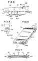
- Fig. 1 to Fig. 4 are explanatory views each illustrating an example of the sterilizing apparatus used for the microwave irradiating sterilization process according to the present invention;
- Fig. 5 is an explanatory view showing a state of waveguides in the first heating chamber in the sterilizing apparatus of Fig. 4;
- Fig. 6 is a perspective view showing an example of supporting holder;
- Fig. 7 is a sectional view taken along the line I - I of Fig. 6;
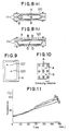
- Figs. 8(a) and (b) are sectional views each showing another example of supporting holder;
- Fig. 9 is an explanatory view indicating positions at which temperatures of packages are measured in Examples 1 and 2, respectively;
- Fig. 10 is an explanatory view indicating positions at which temperatures of packages are measured in Example 3; and
- Fig. 11 is a graphical representation indicating results of the temperatures measured in Example 3.
-
- First of all, an apparatus used for the microwave irradiating sterilization process according to the present invention is constructed in, for example, such that a
first heating chamber 1A in which microwaves are irradiated frommicrowave generators waveguides second heating chamber 1B in which microwaves are irradiated frommicrowave generators waveguides waveguides first heating chamber 1A extends to a position being close to the conveying route of packages, whilst each of thewaveguides second heating chamber 1B is positioned at a wall portion thereof. - Packages A are supplied to a conveyor 8, they are conveyed to the
first heating chamber 1A through amicrowave trap 5, and a material to be sterilized in each of the packages A is partially heated in said first heating chamber. Then, each of the packages A passes through amicrowave trap 6, the whole of such a package A is heated in thesecond heating chamber 1B, and each of the packages thus sterilized passes again through amicrowave trap 7 to be taken out. - In this case, a distance defined between a microwave irradiation mouth of each of the
waveguides first heating chamber 1A may be adjusted by travelling the waveguide within a range of 10 - 100 mm, and a dimension of the irradiation mouth of such awaveguide 11A may be regulated by varying a dimension of a slit defined on the irradiation mouth. - Referring to Fig. 2, a
first heating chamber 2A in which microwaves are irradiated frommicrowave generators waveguides second heating chamber 2B in which microwaves are irradiated frommicrowave generators waveguides waveguide 21A for local heating in thefirst heating chamber 2A extends to a position being close to the conveying route of packages, whilst thelower waveguide 22A for overall heating is positioned at a wall portion thereof. Furthermore, thewaveguide 22B for overall heating is positioned at a wall portion of thesecond heating chamber 2B and thelower waveguide 21B for local heating extends to a position being close to the conveying route of packages in thesecond heating chamber 2B. - Packages A are supplied to a conveyor 8, they are conveyed to the
first heating chamber 2A through amicrowave trap 5, and a material to be sterilized in each of the packages A is heated partially from the upper side and entirely from the under side in said first heating chamber. Then, each of the packages A passes through amicrowave trap 6, such a package A is heated partially from the under side and entirely from the upper side in thesecond heating chamber 2B, and each of the packages thus sterilized passes again through amicrowave trap 7 to be taken out. - Furthermore, two or more of constructions of the second heating chamber may be repeated as shown in Fig. 3.
- In this case, local heating as well as overall heating of packages A may be effected by reversing the order of heating with respect to the top and bottom of each of the packages in
heating chambers - The number of heating chamber is not limited to two, but packages may be heated with repeated constructions of a pair of the aforesaid two heating chambers, if necessary.
- Referring to Fig. 4, each of
first heating parts microwave generators local heating waveguides second heating part 3B in which microwave is irradiated from amicrowave generators 30B through anoverall heating waveguide 31B are disposed on a conveying route of packages A, respectively, in an apparatus used for the microwave irradiating sterilization according to the present invention. Each of thewaveguides first heating parts waveguide 31B in thesecond heating part 3B is positioned at a wall portion thereof. - Supporting holders B, containing packages A, respectively, are supplied to a conveyor 8, they are conveyed to the
first heating parts microwave trap 5, and a material to be sterilized in each of the packages A is heated partially in thesefirst heating parts second heating part 3B. Then, each of the packages A thus sterilized passes again through amicrowave trap 7 to be taken out. - In this case, a distance defined between a microwave irradiation port of each of the
waveguides first heating parts waveguide 31A may be regulated by varying a dimension of a slit defined on the irradiation mouth. - The
waveguides first heating parts - In order that a package A is partially heated by means of a local heating waveguide extending to a position close to a route for conveying packages, it is effective that such a package A is intermittently transferred and stopped so as to locate it immediately over the waveguide.
- While all the above explanations have been made in respect of microwave irradiating sterilization in which local heating waveguides as well as overall heating waveguides are employed, objects of the present invention can be attained by the use of local heating waveguides only.
- For example, a plurality of local heating waveguides are placed at different positions in the direction perpendicular to that along which packages are conveyed, conveying packages are irradiated with microwave from the waveguides disposed at said positions under these packages, and so irradiated packages are further turned over at the intermediate stage of heating, whereby the packages can be uniformly heated.
- Furthermore, a plurality of local heating waveguides are disposed on both the upper and lower sides of a route for conveying packages, and these packages may be irradiated with microwave at different positions in the direction perpendicular to that along which the packages are conveyed as in the case mentioned above. In this case, it becomes possible to more uniformly heat these packages by turning over them at the intermediate stage of such heating.
- Moreover, it is effective to irradiate merely upwardly a material to be sterilized in a package with microwave in a first heating chamber in the case where such material to be sterilized is liquid food exhibiting flow behavior such as soup, stew and the like, whilst it is effective for solid food such as Hamburg steak, steak, roast fish and the like to irradiate such solid food not only upwardly, but also downwardly with microwave.
- In addition, when packages or supporting holders containing such packages are reversed at a overall heating position, a temperature difference between the upper and lower portions inside each package decreases, so that more uniform heating becomes possible.
- A volumetric capacity of a heating chamber provided with said overall heating waveguides is 0.05 - 0.5 m³, and a plurality of such heating chambers are disposed through each trap or partition panel to obtain a unit construction.
- Since a capacity of the heating chamber ranges from 0.05 m³ to 0.5 m³, a microwave distribution in the heating chamber becomes substantially uniform, and as a result the whole of each package can be homogeneously and stably heated.
- In the case where a capacity of the heating chamber is less than 0.05 m³, since a microwave energy density is high, packages are rapidly heated so that there is a dangerous situation where temperature scattering becomes remarkable in each of such packages, besides it becomes difficult to control the heating temperature.
- On the other hand, when a capacity of the heating chamber is more than 0.5 m³, the heating chamber is too large and microwave does not sufficiently diffuse therein, so that a distribution of microwave becomes ununiform in the heating chamber and the heating is not homogeneously carried out.
- A profile of such heating chamber is preferably a substantially cubical shape, because a plurality of packages are present in the respective heating chambers and these packages must be homogeneously irradiated with microwave.
- Sterilization which is effected by passing said packages A through a sterilizer is made after containing the packages in supporting holders each of which is made of a microwave permeable material in order to prevent these packages from bursts thereof.
- As a supporting holder, there is a member made of a microwave permeable material which comprises two
holding plates portion 110 therein, andlock portions shaped retaining members - The
retaining member 112 is constructed so as to have a larger spacing by 0.5 - 3 mm than the total thickness of either side of both the respective ends of theholding plates holding plates - If a difference between a dimension of the spacing in the retaining
member 112 and the total thickness of the holdingplates - On the contrary to the above, when exceeded a difference of 3 mm, although it becomes easy to clamp the holding plates by the retaining member and to take out a package after heating, there is such a dangerous situation where the retaining member is disengaged from the holding plates at the time of heating as well as a fear of bursting such a package.
- Furthermore, preferable is to use such supporting holders each of which is constructed in such that a
heating element 120 is disposed on a holdingplate 111 which is in contact with a package A as shown in Figs. 8(a) and (b) in order to prevent heat release from portions where the package A is in contact with the holdingplates 111. 111. - A material used for the holding plates in said supporting holder is one having heat resistance and a certain bending strength, and an example of which includes, for example, glass filler-filled silicone, glass filler-filled polyphenylenesulfide, and silicone impregnated glass-cloth laminate.
- The retaining
member 112 for clamping these supportingholders - As the
heating element 120 for disposing onto the supportingplates -
- Two microwave oscillators (SMG-130 manufactured by Sanyo Denki K.K.) each having 1.3KW output were placed in a
first heating chamber 1A and asecond heating chamber 1B as their microwave generators, respectively, in a microwave sterilizing apparatus shown in Fig. 1. - In the above case, two
local heating waveguides first heating chamber 1A were positioned in such that an irradiation mouth of each of thelocal heating waveguides overall heating waveguides second heating chamber 1B were positioned in such that an irradiation mouth of each of theoverall heating waveguides - Conveyance of packages was continuously or intermittently carried out, and the following materials to be sterilized were tested.
- The materials to be sterilized were water, carboxymethylcellulose (hereinafter referred to simply as "CMC") aqueous solution A (1.2% concentration, and 4,000 mPas viscosity), CMC aqueous solution B (2.5% concentration, and 64,000 mPas viscosity), and konjak (jelly-like food made from the starch of the devil's-tongue).
- A package prepared by charging a pouch made of an oriented nylon/non-oriented polypropylene laminated film with 130 g each of said materials to be sterilized was used to effect heating sterilization.
- At a preset temperature of 100°C or more. a package was contained in a supporting holder made from glass-filled silicone resin and subjected to heat treatment.
- Temperatures were measured by means of a thermocouple at a central portion 222 and its surrounding
portion 221 as shown in Fig. 9. - Conditions for continuous and intermittent conveyance are shown in Tables 1 and 2, respectively. In either case of conveyance, four packages were adapted to be present in the first and
second heating chambers Table 1 Conditions 1 2 3 1st Heat.Chamber Output (KW) 2.6 2.6 0 Time (sec) 45 70 0 2nd Heat.Chamber Output (KW) 2.6 2.6 2.6 Time (sec) 45 70 135 Supporting Holder no yes yes * Distance between irradiation mouth of first heating part and package: 35 mm
Slit width of irradiation mouth: 30 mmTable 2 Conditions 4 5 6 7 8 1st H.C. Output (KW) 2.6 2.6 2.6 2.6 2.6 2nd H.C. Output (KW) 2.6 2.6 2.6 2.6 2.6 Stopping Period (sec) 5 5 5 5 12 Distance (mm) 35 35 100 35 35 Slit Width (mm) 30 50 30 30 30 Number of Times 1 1 1 2 1 Supporting Holder no no no yes yes * H.C.: Heating Chamber - In case of continuous conveyance, a surrounding portion of each package was more remarkably heated than its central portion thereof irrespective of materials to be sterilized in also the first heating chamber. After completing the second heating, the temperature difference increased further, so that no effect was observed in respect of direct irradiation. In case of water, however, a temperature difference is small as compared with that in case of the other materials to be sterilized, and accordingly influence of convection was observed. In any condition, CMC aqueous solution and konjak had substantially the same tendencies, so that results of the temperature measurement in 1.2% CMC aqueous solution were shown in Table 3.
Table 3 Conditions Heating Temperature Final T.Diff. * After 1st Heating After 2nd Heating Cent.P. Surrd.P. Cent.P. Surrd.P. (°C) (°C) (°C) 1 53 59 81 97 +16 2 68 79 114 138 +24 3 19 19 108 139 +31 4 61 37 86 73 -13 5 56 43 80 81 +1 6 46 52 72 88 +16 7 (once) 60 39 84 73 -11 (twice) 119 99 142 135 -7 8 95 51 136 113 -23 * Temperature at surrounding portion with respect to central portion of package
Cent.P.: Central Portion
Surrd.P.: Surrounding Portion
T.Diff.: Temperature Difference - Sterilization was carried out as described hereinbelow by employing the same microwave oscillators with those used in Example 1 for the sterilizing apparatus shown in Fig. 2.
- In the above case, a
local heating waveguide 21A in two of them in thefirst heating chamber 2A was positioned in such that an irradiation mouth of thelocal heating waveguide 21A extended to be close to a package, whilst the otheroverall heating waveguide 22A was located in such that an irradiation mouth of theoverall heating waveguide 22A did not project from a wall surface of the heating chamber. Furthermore, awaveguide 22B in two of them in thesecond heating chamber 2B was positioned in such that it did not project from a wall surface of the heating chamber, whilst theother waveguide 21B was disposed as in the case of thewaveguide 21A in the first heating chamber. - Conveyance of packages was continuously or intermittently carried out, and the following materials to be sterilized were tested.
- The materials to be sterilized were water, CMC aqueous solution A (1.2% concentration, and 4,000 mPas viscosity), CMC aqueous solution B (2.5% concentration, and 64,000 mPas viscosity), and konjak.
- A package prepared by charging a pouch made of an oriented nylon/non-oriented polypropylene laminated film with 130 g each of said materials to be sterilized was used to effect heating sterilization.
- At a preset temperature of 100°C or more, a package was contained in a supporting holder made from glass-filled silicone resin and subjected to heat treatment.
- Temperatures were measured as in the case of Example 1 by means of a thermocouple at a central portion 222 and its surrounding
portion 221 as shown in Fig. 9. - Conditions for continuous and intermittent conveyance are shown in Tables 4 and 5, respectively. In either case of conveyance, four packages were adapted to be present in the first and
second heating chambers Table 4 Conditions 1 2 1st Heating Chamber Output (KW) 2.6 2.6 Time (sec) 45 70 2nd Heating Chamber Output (KW) 2.6 2.6 Time (sec) 45 70 Supporting Holder no yes * Distance between irradiation mouth of first heating part and package: 35 mm
Slit width of irradiation mouth: 30 mmTable 5 Conditions 3 4 5 6 7 1st H.C. Output (KW) 2.6 2.6 2.6 2.6 2.6 2nd H.C. Output (KW) 2.6 2.6 2.6 2.6 2.6 Stopping Period (sec) 5 5 5 5 12 Distance (mm) 35 35 50 35 35 Slit Width (mm) 30 50 30 30 30 Number of Times 1 1 1 2 1 Supporting Holder no no no yes yes - In case of continuous conveyance, a surrounding portion of each package was more remarkably heated than its central portion thereof irrespective of materials to be sterilized in also the first heating chamber. After completing the second heating, the temperature difference increased further, so that no effect was observed in respect of direct irradiation. In case of water, however, a temperature difference is small as compared with that in case of the other materials to be sterilized, and accordingly influence of convection was observed. In any condition, CMC aqueous solution and konjak had substantially the same tendencies, so that results of the temperature measurement in 1.2% CMC aqueous solution were shown in Table 6.
Table 6 Conditions Heating Temperature Final T.Diff. * After 1st Heating After 2nd Heating Cent.P. Surrd.P. Cent.P. Surrd.P. (°C) (°C) (°C) 1 50 58 82 96 +14 2 68 79 114 138 +24 3 53 48 85 76 -13 4 49 52 80 82 +2 5 48 54 74 85 +11 6 (once) 52 48 84 74 -10 (twice) 111 103 140 134 -6 7 75 70 128 120 -8 * Temperature at surrounding portion with respect to central portion of package - From the results shown in Table 6. it was found that direct irradiation of package A with microwave in the first heating chamber or the second heating chamber was effective for heating in a central portion of the package in case of intermittent conveyance therefor. The advantageous effects thereof are dependent upon a distance between irradiation mouth and material to be sterilized, a size of the irradiation mouth, and a period for heating, and thus substantially uniform heating becomes possible by combining these factors so as to be in conformity with the shape of a package.
- Sterilization was carried out as described hereinbelow by employing the sterilizing apparatus shown in Figs. 3 and 4 provided with the same microwave oscillators with those used in Example 1.
- In the sterilizing apparatus,
local heating waveguides first heating parts overall heating waveguide 31B was disposed in asecond heating part 3B in such that the overall heating waveguide did not project from a wall surface of the heating chamber. - In the above arrangement, supporting holders each containing a package were intermittently conveyed so as to travel for 2 seconds and then to stop for 4 seconds. It is to be noted that portions a and b indicated in Fig. 10 were alternately irradiated with microwave by means of the
waveguides first heating parts - Sterilization was effected on CMC aqueous solution A (1.2% concentration, and 2,000 mPas viscosity).
- A package prepared by charging a pouch made of an oriented nylon (25µ)/non-oriented polypropylene (70µ) laminated film with 180 g each of said material to be sterilized was used to effect heating sterilization.
- As a supporting holder for containing a package, one which is made from glass-filled silicone resin was used.
- Temperatures of a package after heating were continuously measured by means of an optical fiber thermometer (3Z4D manufactured by Tateishi Denki) with respect to positions (2), (3), (5) and (6) in the positions (1) - (9) indicated in Fig. 10.
- Packages were heated in such a way that each package passed repeatedly through two first heating parts five times, and then passed through one second heating part as well as two first heating parts one time. Temperatures of the packages thus heated were measured at the above respective positions, and the results thereof are indicated in Fig. 11.
- In the above case, packages were conveyed in such a manner that two packages each were present in the respective heating parts.
- As is apparent from Fig. 11, there were scarce temperature differences between the above-mentioned positions even after the elapse of 80 seconds from the start of irradiation in the present example, and a temperature difference of 20°C or less was observed between the positions (3) and (2) at the time of completing such heating.
- A supporting holder having a profile shown in Fig. 8(a) and made from glass-filled silicone resin was prepared. A sample of the above supporting holder to which is attached a heating element was compared with another sample of said supporting holder without any heating element. As a heating element, aluminum deposited polyethylene terephthalate (a deposit thickness of 200 Å) was used, and the supporting holder provided with the heating element was further laminated with polyimide on the side of said deposit.
- A pouch made of an oriented nylon film (25 µm)/a non-oriented polypropylene film (70 µm) was employed for a package A, and the package A was charged with 180 g of white sauce. Each of these packages A thus charged was heated by a sterilizing apparatus being provided with two first heating chambers to each of which an irradiation mouth of a waveguide extends from a microwave oscillator (SMG-130® manufactured by Sanyo Denki K.K.) having 1.3 KW output shown in Fig. 4 so as to be close to the underside of a conveyor and further provided with a second heating chamber onto the upper wall surface of which an irradiation mouth of another waveguide extends from the same type of microwave oscillator as that described above, and in the sterilizing apparatus, the packages A are continuously conveyed by means of a conveyor traversing these heating chambers. After the heat treatment, the temperatures at four positions A - D shown in Fig. 8(a) were continuously measured by means of an optical fiber thermometer (3Z4D® manufactured by Tateishi Denki). Microwave irradiating conditions were 600 W output per a pouch, and a total heating time of 4 minutes. The heating sterilization was carried out in such that each package passed through said sterilizing apparatus for 2 minutes and 30 seconds, the heated package was then reversed once, and thereafter said package passed through said apparatus for 1 minute and 30 seconds. Finally, the positions B and D located at the underside of each package. Averages of the measured results are shown in Table 7.
Table 7 Position Maximum Arrived Temperature (°C) Example 4 Comparative Example 1 A 136 137 B 133 133 C 135 124 D 140 112 - As is apparent from Table 7, heat release at its surrounding portion where there is a sealed portion of each package was prevented by the use of the heating element, so that the whole package was substantially uniformly heated.
- A supporting holder made of a silicone-impregnated glass-cloth laminate and having a profile as shown in Fig. 8(b) was prepared as the supporting holder used in the present example, and a silicone resin with which is admixed manganese-magnesium ferrite powder was prepared as the heating material for the present example. The supporting holder wherein the heating material has been attached to a holding plate on the side of the cover of said supporting holder (Example 5) was compared with the supporting holder without any heating material (Comparative Example 2).
- A package A was composed of a molded tray prepared from polypropylene (500 µm)/saponified ethylene-vinyl acetate copolymer (50 µm)/polypropylene (500 µm) and a cover prepared from non-oriented nylon (15 µm)/polyvinylidene chloride (20 µm) /non-oriented polypropylene (70 µm). The molded tray was charged with 280 g of mixed vegetables, and then sealed hermetically with said cover to prepare a sample. The samples thus prepared were heated, and temperatures of which were measured by employing the same apparatus and implement with those of Example 4. Temperatures were measured at four positions A, B, C and D indicated in Fig. 8(b). Microwave irradiating conditions were 600 W output per a tray, and a total heating time of 6 minutes. The heating sterilization was carried out in such a manner that each package passed through said sterilizing apparatus for 4 minutes, the heated package was then reversed once, and thereafter said package passed through said apparatus for 2 minutes in such that a location of the cover of the package is finally at the underside thereof. The measured results are shown in Table 8.
Table 8 Position Maximum Arrived Temperature (°C) Example 5 Comparative Example 2 A 132 133 B 141 123 C 134 136 D 125 125 - As is apparent from Table 8, it was found that heat release from the cover side of each package could be prevented by the use of the heating material. Since the tray has a thick thickness, heat release therefrom is suppressed.
- According to the process of the present invention, substantially homogeneous heating can be attained under such situation that there are slight temperature differences between respective portions in a package in the course of heat elevation of the package by means of microwave irradiation, besides there are also scarce temperature differences even at the time of completing the heating. Accordingly, homogeneous heating by means of microwave irradiation which could not have been realized in accordance with a conventional microwave irradiating process becomes possible in the process of the present invention.
- Thus, it makes possible to reduce temperature scattering in a package in continuous microwave irradiating sterilization, besides deterioration in quality of foods can be prevented, and homogeneous heating becomes possible for a short period of time according to the process of the present invention.
- The present invention provides a microwave irradiating sterilization process in which local irradiation is repeated by means of local heating waveguides being close to the undermentioned package in the case where either such a package charged with a material to be sterilized and then sealed hermetically or a supporting holder containing the package is irradiated with microwave while conveying continuously such packages thereby heating and sterilizing the material to be sterilized.
Claims (11)
- A microwave irradiating sterilization process, wherein conveying packages charged with a material to be sterilized are irradiated by passing microwaves to heat and sterilize the packages, wherein irradiation is effected by a plurality of local heating waveguides installed at a distance from said packages, conveyed intermittently or continously
characterized in that said packages (A) are received in supporting bodies (B) each composed of two supporting plates (111) formed of a material having heat resisting and pressure resisting properties and through which a microwave can be permeated, and in that said supporting bodies (B) are turned over during conveying, so that the process can be carried out under normal pressure. - The microwave irradiating sterilization process as claimed in claim 1,
characterized by means of overall heating waveguides (11B, 22A, 22B, 31B) on a wall portion of a heating chamber (1B; 2A, 2B; 3B) effecting overall irradiation also to the fore end of said packages (A). - The microwave irradiating sterilization process as claimed in claim 1 or 2,
characterized in that the distance from the irradation mouth of each said waveguides (11A; 21A, 21B; 31A) to said packages (A) is adjustable in a range of from 10 to 100 mm. - A microwave irradiating sterilization process as claimed in one of the claims 1-3 wherein the irradiation by means of the local heating waveguides is effected alternately at different positions perpendicular to the conveying direction of the packages.
- A microwave irradiating sterilization process as claimed in one of the claims 1-4 wherein the irradiation by means of said local heating waveguides is effected from the lower side or in both upper and lower sides.
- A microwave irradiating sterilization process as claimed in claim 5 wherein the irradiation by means of said local heating waveguides is effected alternately at different positions perpendicular to the conveying direction of the packages.
- A microwave irradiating sterilization process as claimed in one of the claim 1-6 wherein the conveyance of the packages is the intermittent transport in which the packages stop at positions of the local heating waveguides.
- A microwave irradiating sterilization process as claimed in one of the claims 1-7 characterized in that said supporting body has substantially the same volumetric capacity as that of said package,
- A microwave irradiating sterilization process as claimed in one of the claims 1-8 wherein a volume of a heating chamber provided with overall heating waveguides is 0.05 m³ - 0.5 m³.
- A microwave irradiating sterilization process as claimed in one of the claims 1-9 wherein a heat generating material heat-generated by the irradiation of microwave is provided in the peripheral portion of the inner surface of the supporting body.
- A microwave irradiating sterilization process as claimed in one of the claims 1-10 wherein a supporting body having a clearance of 0.5 to 3 mm is used between two supporting plates.
Applications Claiming Priority (8)
| Application Number | Priority Date | Filing Date | Title |
|---|---|---|---|
| JP28148486A JPS63133970A (en) | 1986-11-26 | 1986-11-26 | Nicrowave thermal sterilization |
| JP281484/86 | 1986-11-26 | ||
| JP203237/86 | 1986-12-29 | ||
| JP20323786U JPS63107193U (en) | 1986-12-29 | 1986-12-29 | |
| JP62057442A JPH0636396B2 (en) | 1987-03-12 | 1987-03-12 | Microwave heating sterilizer |
| JP57442/87 | 1987-03-12 | ||
| JP62244566A JPH0622537B2 (en) | 1987-09-29 | 1987-09-29 | Microwave heating sterilization method |
| JP244566/87 | 1987-09-29 |
Publications (2)
| Publication Number | Publication Date |
|---|---|
| EP0269073A1 EP0269073A1 (en) | 1988-06-01 |
| EP0269073B1 true EP0269073B1 (en) | 1991-11-27 |
Family
ID=27463505
Family Applications (1)
| Application Number | Title | Priority Date | Filing Date |
|---|---|---|---|
| EP87117328A Expired EP0269073B1 (en) | 1986-11-26 | 1987-11-24 | Microwave irradiating sterilization process |
Country Status (6)
| Country | Link |
|---|---|
| US (1) | US4808782A (en) |
| EP (1) | EP0269073B1 (en) |
| AU (1) | AU606628B2 (en) |
| CA (1) | CA1285370C (en) |
| DE (1) | DE3774842D1 (en) |
| DK (1) | DK618387A (en) |
Cited By (1)
| Publication number | Priority date | Publication date | Assignee | Title |
|---|---|---|---|---|
| CN100355321C (en) * | 2002-04-09 | 2007-12-12 | 托普斯食品股份有限公司 | Method and device for heating sealed cooked food in dish by microwave |
Families Citing this family (63)
| Publication number | Priority date | Publication date | Assignee | Title |
|---|---|---|---|---|
| EP0287760A1 (en) * | 1987-04-15 | 1988-10-26 | HERMANN BERSTORFF Maschinenbau GmbH | Device for the uniform and rapid heating, pasteurization or sterilization of foods or the like |
| DE3811063A1 (en) * | 1988-03-31 | 1989-10-19 | Berstorff Gmbh Masch Hermann | DEVICE FOR CONTINUOUSLY HEATING, PASTEURIZING OR STERILIZING FOOD OR THE LIKE |
| US5039495A (en) * | 1988-04-21 | 1991-08-13 | Flexiclave, Inc. | Apparatus for sterilizing articles such as dental handpieces |
| US5019344A (en) * | 1988-04-21 | 1991-05-28 | Flexiclave, Inc. | Method for sterilizing articles such as dental handpieces |
| US5871702A (en) * | 1988-04-21 | 1999-02-16 | Flexiclave, Inc. | Methods and apparatus for sterilizing objects |
| IT1226340B (en) * | 1988-07-18 | 1991-01-09 | Barilla Flli G & R | MACHINE FOR HEAT TREATMENT AND STERILIZATION WITH MICROWAVES OF PRE-PACKED FOODS. |
| DE3830867C1 (en) * | 1988-09-10 | 1990-01-18 | Hermann Berstorff Maschinenbau Gmbh, 3000 Hannover, De | |
| DE3834574A1 (en) * | 1988-10-11 | 1990-04-12 | Berstorff Gmbh Masch Hermann | WORKING METHOD AND APPARATUS FOR EQUALLY RENDERING THROUGH MICROWAVES |
| US5024145A (en) * | 1989-08-28 | 1991-06-18 | Flakee Mills, Inc. | Vibratory bulk material processor and method |
| US5106594A (en) * | 1990-03-30 | 1992-04-21 | Stericycle, Inc. | Apparatus for processing medical waste |
| US5035858A (en) * | 1989-10-13 | 1991-07-30 | Stericycle, Inc. | Method for disinfecting medical materials |
| US5226065A (en) * | 1989-10-13 | 1993-07-06 | Stericycle, Inc. | Device for disinfecting medical materials |
| US5709842A (en) * | 1989-10-13 | 1998-01-20 | Stericycle, Inc. | Apparatus and method for processing medical waste |
| US5508004A (en) * | 1989-10-13 | 1996-04-16 | Stericycle, Inc. | Apparatus and method for processing medical waste |
| DE4001318A1 (en) * | 1990-01-18 | 1991-07-25 | Berstorff Gmbh Masch Hermann | DEVICE FOR PASTEURIZING, STERILIZING AND UNIFORM AND QUICKLY WARMING FOOD PRODUCTS |
| EP0522083A4 (en) * | 1990-03-30 | 1993-05-19 | Iit Research Institute | Method and apparatus for rendering medical materials safe |
| EP0522056A4 (en) * | 1990-03-30 | 1993-05-26 | Iit Research Institute | Method and apparatus for treating hazardous waste or other hydrocarbonaceous material |
| WO1992000766A1 (en) * | 1990-07-06 | 1992-01-23 | Iit Research Institute | Method and apparatus for rendering medical materials safe |
| AU8425091A (en) * | 1990-07-06 | 1992-02-04 | Iit Research Institute | Method and apparatus for rendering medical materials safe |
| US5198255A (en) * | 1991-07-08 | 1993-03-30 | General Mills, Inc. | Stability improvements of oat R-T-E cereals by high intensity microwave heating |
| US5338556A (en) * | 1991-07-08 | 1994-08-16 | General Mills, Inc. | High intensity microwave puffing of thick R-T-E cereal flakes |
| US5200222A (en) * | 1991-07-08 | 1993-04-06 | General Mills, Inc. | Microwave toasting of puffed R-T-E cereals |
| US5196218A (en) * | 1991-07-08 | 1993-03-23 | General Mills, Inc. | Microwave toasting of unpuffed R-T-E cereals |
| US5182127A (en) * | 1991-09-23 | 1993-01-26 | General Mills, Inc. | Microwave tempering of cooked cereal pellets or pieces |
| US5369250A (en) * | 1991-09-27 | 1994-11-29 | Apv Corporation Limited | Method and apparatus for uniform microwave heating of an article using resonant slots |
| US5884417A (en) * | 1992-02-10 | 1999-03-23 | Her Majesty The Queen In Right Of Canada, As Represented By The Minister Of The Environment | Microwave-assisted separations using volatiles |
| US5732476A (en) * | 1992-02-10 | 1998-03-31 | Pare; J.R. Jocelyn | Microwave-assisted separations using volatiles, and apparatus therefor |
| US5519947A (en) * | 1992-02-10 | 1996-05-28 | Her Majesty The Queen In Right Of Canada, As Represented By The Minister Of The Environment | Microwave-assisted generation of volatiles, of supercritical fluid, and apparatus therefor |
| CA2060931C (en) * | 1992-02-10 | 1996-12-17 | J. R. Jocelyn Pare | Microwave-assisted generation of volatiles, of supercritical fluid, and apparatus therefor |
| US5675909A (en) * | 1992-02-10 | 1997-10-14 | Her Majesty The Queen In Right Of Canada, As Represented By The Minister Of Environment | Microwave-assisted separations using volatiles |
| US5378319A (en) * | 1993-05-07 | 1995-01-03 | Tran Industrial Research Inc. | Lime mud calcining using dielectric hysteresis heating |
| US5436432A (en) * | 1993-10-14 | 1995-07-25 | Cyr; Samuel A. | Microwave autoclave apparatus |
| US5607612A (en) * | 1994-10-07 | 1997-03-04 | Quiclave, L.L.C. | Container for microwave treatment of surgical instrument with arcing prevention |
| US5645748A (en) * | 1994-10-07 | 1997-07-08 | Quiclave, L.L.C. | System for simultaneous microwave sterilization of multiple medical instruments |
| US5552112A (en) * | 1995-01-26 | 1996-09-03 | Quiclave, Llc | Method and system for sterilizing medical instruments |
| US5541390A (en) * | 1995-03-20 | 1996-07-30 | Cidelcem Industries | Tunnel oven for microwave heating and cooking foods |
| US5641423A (en) * | 1995-03-23 | 1997-06-24 | Stericycle, Inc. | Radio frequency heating apparatus for rendering medical materials |
| DE19515342A1 (en) * | 1995-04-26 | 1996-10-31 | Widia Gmbh | Process, device for the thermal treatment of substances in a microwave oven and use of this process and this device |
| EP0885569B1 (en) * | 1997-06-17 | 2002-09-04 | Yamamoto Vinita Co., Ltd. | An apparatus for heating prepackaged food |
| EP0968661A4 (en) | 1997-08-14 | 2000-01-05 | Yamamoto Vinita Co Ltd | PROCESS AND DEVICE FOR PASTEURIZING PACKAGED FOOD PRODUCT |
| US6248985B1 (en) | 1998-06-01 | 2001-06-19 | Stericycle, Inc. | Apparatus and method for the disinfection of medical waste in a continuous manner |
| IT1304813B1 (en) * | 1998-07-01 | 2001-04-05 | Omac Internat Ltd | PROCEDURE FOR SANITIZATION OF MINCED MEAT AND PLANTS. |
| ITTV20020120A1 (en) * | 2002-10-18 | 2004-04-19 | S M C Srl | TUNNEL FOR THE CONDITIONING OF FOOD PRODUCTS |
| US8039031B2 (en) * | 2003-05-16 | 2011-10-18 | Energy Systems Engineering LLC | Methods and apparatus for treating plant products using electromagnetic fields |
| US7119313B2 (en) * | 2003-09-08 | 2006-10-10 | Washington State University Research Foundation | Apparatus and method for heating objects with microwaves |
| EP2194800B1 (en) * | 2007-08-28 | 2018-12-05 | Texas Tech University System | Method and system for preserving food |
| JP5142261B2 (en) * | 2007-12-12 | 2013-02-13 | 株式会社サイダ・Fds | Microwave irradiation device |
| US9204501B1 (en) | 2010-03-17 | 2015-12-01 | Cibus Wave LLC | Microwave system and method |
| US9120587B2 (en) * | 2010-09-10 | 2015-09-01 | Pepsico, Inc. | In-package non-ionizing electromagnetic radiation sterilization |
| US9642195B2 (en) | 2012-03-14 | 2017-05-02 | Microwave Materials Technologies, Inc. | Enhanced microwave system utilizing tilted launchers |
| CN105722517A (en) * | 2013-08-06 | 2016-06-29 | 柯惠有限合伙公司 | Microwave sterilization of pharmaceutical cyanoacrylate esters compositions |
| WO2017059441A1 (en) | 2015-10-01 | 2017-04-06 | 915 Labs, LLC | Arrangement of articles in a carrier for microwave heating |
| EP3169141A1 (en) | 2015-11-13 | 2017-05-17 | Bottle-Top Development Co. | Microwave heating system |
| US10258066B2 (en) * | 2016-07-18 | 2019-04-16 | Washington State University | Microwave sterilization or pasteurization transport carriers and system |
| JP2020511755A (en) | 2017-03-15 | 2020-04-16 | 915 ラボ、エルエルシー | Multi-pass microwave heating system |
| AU2018235948B2 (en) | 2017-03-15 | 2023-05-18 | 915 Labs, Inc. | Energy control elements for improved microwave heating of packaged articles |
| KR102541079B1 (en) | 2017-04-17 | 2023-06-08 | 915 랩스, 엘엘씨 | Microwave assisted sterilization and pasteurization systems using synergistic packaging, carrier and launcher configurations |
| JP6915785B2 (en) * | 2018-03-30 | 2021-08-04 | 森永乳業株式会社 | Microwave heating device, microwave heating method, and method for manufacturing packaged foods |
| EP3994957A2 (en) | 2019-07-01 | 2022-05-11 | A.L.M. Holding Company | Microwave heating system with suppression tunnel and related features |
| JP7852034B2 (en) | 2021-08-16 | 2026-04-27 | ストール マシーナリ カンパニー,エルエルシー | Can drying moisture control system |
| AU2022463711A1 (en) | 2021-09-08 | 2024-03-07 | A.L.M. Holding Company | Microwave heating applied to mining and related features |
| US20230210145A1 (en) * | 2022-01-06 | 2023-07-06 | A.L.M. Holding Co. | Microwave heating applied to food additives |
| FR3147112B1 (en) * | 2023-03-30 | 2025-03-28 | Innovation & Dev Company | Microwave heating device for continuous heat treatment of organic products in solid or pasty state |
Family Cites Families (9)
| Publication number | Priority date | Publication date | Assignee | Title |
|---|---|---|---|---|
| US2820127A (en) * | 1953-03-30 | 1958-01-14 | Raytheon Mfg Co | Microwave cookers |
| FR1533943A (en) * | 1967-06-12 | 1968-07-26 | Cellophane Sa | Continuous packaging and sterilization process for food products |
| US3551090A (en) * | 1968-07-29 | 1970-12-29 | Robert C Brumfield | Microwave reactor and process for asepsis |
| FR2327700A1 (en) * | 1975-10-09 | 1977-05-06 | Meisel Nicolas | MICROWAVE TUNNEL OVEN FOR CONTINUOUS PROCESSING OF FOOD PRODUCTS |
| US4405850A (en) * | 1978-10-06 | 1983-09-20 | Raytheon Company | Combination microwave heating apparatus |
| JPS5764588U (en) * | 1980-10-07 | 1982-04-17 | ||
| EP0152023A3 (en) * | 1984-02-09 | 1987-02-04 | Kimberly-Clark Corporation | Sanitizing method for absorbent articles |
| US4687895A (en) * | 1984-07-30 | 1987-08-18 | Superwave Technology, Inc. | Conveyorized microwave heating system |
| DE3432341A1 (en) * | 1984-09-03 | 1986-03-06 | Hermann Berstorff Maschinenbau Gmbh, 3000 Hannover | METHOD AND SYSTEM FOR CONTINUOUS PASTEURIZING OF FOODSTUFFS |
-
1987
- 1987-11-19 US US07/122,788 patent/US4808782A/en not_active Expired - Fee Related
- 1987-11-24 EP EP87117328A patent/EP0269073B1/en not_active Expired
- 1987-11-24 DE DE8787117328T patent/DE3774842D1/en not_active Expired - Lifetime
- 1987-11-25 AU AU81672/87A patent/AU606628B2/en not_active Ceased
- 1987-11-25 DK DK618387A patent/DK618387A/en not_active Application Discontinuation
- 1987-11-25 CA CA000552681A patent/CA1285370C/en not_active Expired - Lifetime
Cited By (1)
| Publication number | Priority date | Publication date | Assignee | Title |
|---|---|---|---|---|
| CN100355321C (en) * | 2002-04-09 | 2007-12-12 | 托普斯食品股份有限公司 | Method and device for heating sealed cooked food in dish by microwave |
Also Published As
| Publication number | Publication date |
|---|---|
| DK618387D0 (en) | 1987-11-25 |
| AU8167287A (en) | 1988-06-02 |
| DE3774842D1 (en) | 1992-01-09 |
| AU606628B2 (en) | 1991-02-14 |
| EP0269073A1 (en) | 1988-06-01 |
| CA1285370C (en) | 1991-07-02 |
| DK618387A (en) | 1988-05-27 |
| US4808782A (en) | 1989-02-28 |
Similar Documents
| Publication | Publication Date | Title |
|---|---|---|
| US4808782A (en) | Microwave irradiating sterilization process | |
| US3892058A (en) | Process for the preparation of high-temperature short-time sterilized packaged articles | |
| US3261140A (en) | Microwave sterilization and vacuumizing of products in flexible packages and apparatus therefor | |
| US3974355A (en) | Method for effecting uniform heating of an organic product particularly for the purpose of preserving the product and apparatus therefor | |
| US4091119A (en) | Method for uniform heating of a foodstuff for preservation and apparatus therefor | |
| JPH0227968A (en) | Method of thermally stabilizing prepackaged food continuously | |
| CN106793812A (en) | Microwave retort systems, methods for heating food products using microwave retort systems, and formulating food products for microwave retort | |
| EP0240571A1 (en) | Microwave-heated cooked foods | |
| US3672907A (en) | Method of thermally processing a comestible product | |
| JPH1146741A (en) | Manufacturing method of preserved food | |
| JP3676125B2 (en) | Microwave sterilization method | |
| JP2625859B2 (en) | Microwave heating sterilization method | |
| JPH0157946B2 (en) | ||
| JPH06237707A (en) | Microwave heating support, heating method using the same, and microwave heating device | |
| JPH0636396B2 (en) | Microwave heating sterilizer | |
| JP3238521B2 (en) | Sterilization and cooking of sealed packaged food | |
| JPH06296478A (en) | Production of hermetically sealed packaged food and microwave heating and pressurizing sterilizer | |
| JPS60244274A (en) | Microwave sterilization of food | |
| JPH025389B2 (en) | ||
| JP2893604B2 (en) | Microwave oven container | |
| JPH025390B2 (en) | ||
| JP2000018595A (en) | Microwave heating jig | |
| JPH0622537B2 (en) | Microwave heating sterilization method | |
| EP1283179A1 (en) | Microwave-heatable food product package | |
| JP2601023Y2 (en) | Microwave transparent container |
Legal Events
| Date | Code | Title | Description |
|---|---|---|---|
| PUAI | Public reference made under article 153(3) epc to a published international application that has entered the european phase |
Free format text: ORIGINAL CODE: 0009012 |
|
| AK | Designated contracting states |
Kind code of ref document: A1 Designated state(s): DE FR GB NL SE |
|
| 17P | Request for examination filed |
Effective date: 19881115 |
|
| 17Q | First examination report despatched |
Effective date: 19900314 |
|
| GRAA | (expected) grant |
Free format text: ORIGINAL CODE: 0009210 |
|
| AK | Designated contracting states |
Kind code of ref document: B1 Designated state(s): DE FR GB NL SE |
|
| REF | Corresponds to: |
Ref document number: 3774842 Country of ref document: DE Date of ref document: 19920109 |
|
| ET | Fr: translation filed | ||
| PLBE | No opposition filed within time limit |
Free format text: ORIGINAL CODE: 0009261 |
|
| STAA | Information on the status of an ep patent application or granted ep patent |
Free format text: STATUS: NO OPPOSITION FILED WITHIN TIME LIMIT |
|
| 26N | No opposition filed | ||
| EAL | Se: european patent in force in sweden |
Ref document number: 87117328.2 |
|
| PGFP | Annual fee paid to national office [announced via postgrant information from national office to epo] |
Ref country code: FR Payment date: 19951109 Year of fee payment: 9 |
|
| PGFP | Annual fee paid to national office [announced via postgrant information from national office to epo] |
Ref country code: GB Payment date: 19951115 Year of fee payment: 9 |
|
| PGFP | Annual fee paid to national office [announced via postgrant information from national office to epo] |
Ref country code: SE Payment date: 19951116 Year of fee payment: 9 |
|
| PGFP | Annual fee paid to national office [announced via postgrant information from national office to epo] |
Ref country code: DE Payment date: 19951128 Year of fee payment: 9 |
|
| PGFP | Annual fee paid to national office [announced via postgrant information from national office to epo] |
Ref country code: NL Payment date: 19951129 Year of fee payment: 9 |
|
| PG25 | Lapsed in a contracting state [announced via postgrant information from national office to epo] |
Ref country code: GB Effective date: 19961124 |
|
| PG25 | Lapsed in a contracting state [announced via postgrant information from national office to epo] |
Ref country code: SE Effective date: 19961125 |
|
| PG25 | Lapsed in a contracting state [announced via postgrant information from national office to epo] |
Ref country code: NL Effective date: 19970601 |
|
| GBPC | Gb: european patent ceased through non-payment of renewal fee |
Effective date: 19961124 |
|
| PG25 | Lapsed in a contracting state [announced via postgrant information from national office to epo] |
Ref country code: FR Effective date: 19970731 |
|
| NLV4 | Nl: lapsed or anulled due to non-payment of the annual fee |
Effective date: 19970601 |
|
| PG25 | Lapsed in a contracting state [announced via postgrant information from national office to epo] |
Ref country code: DE Effective date: 19970801 |
|
| EUG | Se: european patent has lapsed |
Ref document number: 87117328.2 |
|
| REG | Reference to a national code |
Ref country code: FR Ref legal event code: ST |