EP0268777A1 - Apparatus and process for detecting leaks using a tracer gas - Google Patents
Apparatus and process for detecting leaks using a tracer gas Download PDFInfo
- Publication number
- EP0268777A1 EP0268777A1 EP87113973A EP87113973A EP0268777A1 EP 0268777 A1 EP0268777 A1 EP 0268777A1 EP 87113973 A EP87113973 A EP 87113973A EP 87113973 A EP87113973 A EP 87113973A EP 0268777 A1 EP0268777 A1 EP 0268777A1
- Authority
- EP
- European Patent Office
- Prior art keywords
- valve
- pump
- turbomolecular pump
- tested
- suction
- Prior art date
- Legal status (The legal status is an assumption and is not a legal conclusion. Google has not performed a legal analysis and makes no representation as to the accuracy of the status listed.)
- Granted
Links
Images

Classifications
-
- G—PHYSICS
- G01—MEASURING; TESTING
- G01M—TESTING STATIC OR DYNAMIC BALANCE OF MACHINES OR STRUCTURES; TESTING OF STRUCTURES OR APPARATUS, NOT OTHERWISE PROVIDED FOR
- G01M3/00—Investigating fluid-tightness of structures
- G01M3/02—Investigating fluid-tightness of structures by using fluid or vacuum
- G01M3/04—Investigating fluid-tightness of structures by using fluid or vacuum by detecting the presence of fluid at the leakage point
- G01M3/20—Investigating fluid-tightness of structures by using fluid or vacuum by detecting the presence of fluid at the leakage point using special tracer materials, e.g. dye, fluorescent material, radioactive material
- G01M3/202—Investigating fluid-tightness of structures by using fluid or vacuum by detecting the presence of fluid at the leakage point using special tracer materials, e.g. dye, fluorescent material, radioactive material using mass spectrometer detection systems
Definitions
- the present invention relates to a tracer gas leak detection installation comprising a primary mechanical pump, the suction of which is connected, on the one hand to the part to be tested by means of a first valve and on the other hand to the discharge of a secondary turbomolecular pump via a second valve, the suction of said turbomolecular pump being connected to the part to be tested via a third valve, a spectrometric cell being further connected on the side of the suction of said turbomolecular pump.
- the spectrometric cell 1 being stopped, the first valve 2, the second valve 3 and the third valve 4 being closed, the primary mechanical pump 5 is started and the second valve 3 is opened.
- the pressure gauge 6 indicates a pressure of less than 1 mb and controls the starting of the turbomolecular pump 7.
- the pressure indicated by the pressure gauge 8 drops from 10 ⁇ 2 mb to 10 ⁇ 6 mb and we are then able to light the filament of the spectrometric cell 1.
- the second valve 3 is closed and the first valve 2 is opened.
- the primary pump 5 then empties the part to be tested 9.
- the pressure in the part to be tested measured by a pressure gauge 10
- becomes less than 1 mb we closes the first valve 2 and opens the second valve 3.
- the third valve 4 can be opened slowly so that the pressure indicated by the pressure gauge 8 does not rise above 10 ⁇ 4 mb.
- the leakage measurement is carried out when the third valve 4 is wide open.
- the object of the present invention is to reduce the pumping time of the part to be tested.
- the subject of the invention is therefore an installation for detecting tracer gas leak of the type described above, characterized in that said turbomolecular pump consists of two stages in series, at the separation of which leads to an intermediate suction orifice connected to the part to be tested via a fourth valve and whose first stage, located on the side of the spectrometric cell, has a high helium compression rate and whose second stage, located on the side of the primary pump has a high nitrogen flow rate.
- the installation comprises a primary mechanical pump 5, the suction of which is connected to a part to be tested 9 by a pipe 13 provided with a first valve 2.
- the suction of the primary pump 5 is further connected by a pipe 14 provided with a second valve 3 to the discharge 17 of a secondary turbomolecular pump 7.
- the suction of the turbomolecular pump 7 is connected by a pipe 15, provided a third valve 4, to the part to be tested 9.
- a spectrometric cell 1 is connected to the suction of the turbomolecular pump 7.
- the turbomolecular pump 7 consists of two stages in series and comprises between these two stages an intermediate suction orifice 16 which is connected, by a pipe 11 provided with a fourth valve 12, to the part to be test 9.
- turbomolecular pump 7 is constructed so that its first stage, located in its upper half, on the side of the spectrometric cell 1 has a high compression ratio of helium to reduce the background noise of the helium air and so that its second stage, located in its lower half-part on the side of the primary pump 5, has a high nitrogen flow rate in order to reduce the pumping time of the part.
- Pressure gauges 6, 8 and 10 are used to measure pressures at different levels.
- the pressure gauge 6 indicates a pressure of less than 1 mb and controls the start of the turbomolecular pump 7. When its speed of rotation is reached, the pressure indicated by the pressure gauge 8 drops to 10 ⁇ 6 mb.
- the part to be tested 9 is then connected to the inlet orifice 18 of the entire installation, commonly enclosed in a box called a detector.
- the tracer gas such as helium, is contained in an enclosure surrounding the part 9 and represented by dotted lines 19 in the figure.
- the room itself contains air at atmospheric pressure.
- the part 9 is then emptied by closing the second valve 3 and by opening the first valve 2.
- the primary pump 5 evacuates the air from the part 9 and when the pressure gauge 10 indicates a pressure which becomes less than 1 mb, it is then closed the first valve 2 and the second valve 3 and the fourth valve are opened 12.
- the part to be tested is then emptied by a part of the turbomolecular pump 7 and by the primary pump 5 connected in series.
- the fourth valve 12 When the pressure measured by the pressure gauge 10 reaches 10 ⁇ 2 mb, the fourth valve 12 is then closed, then after a few minutes, the third valve 4, which is an inlet valve, is slowly opened, so that the pressure in cell 1 indicated by pressure gauge 8 does not rise above 10 ⁇ 4 mb.
- the leakage measurement is carried out when the valve 4 is wide open.
Landscapes
- Physics & Mathematics (AREA)
- General Physics & Mathematics (AREA)
- Examining Or Testing Airtightness (AREA)
- Emergency Alarm Devices (AREA)
- Measuring Volume Flow (AREA)
- Non-Positive Displacement Air Blowers (AREA)
Abstract
Description
La présente invention concerne une installation de détection de fuite à gaz traceur comprenant une pompe mécanique primaire dont l'aspiration est reliée, d'une part à pièce à tester par l'intermédiaire d'une première vanne et d'autre part au refoulement d'une pompe secondaire turbomoléculaire par l'intermédiaire d'une seconde vanne, l'aspiration de ladite pompe turbomoléculaire étant reliée à la pièce à tester par l'intermédiaire d'une troisième vanne, une cellule spectrométrique étant en outre reliée du côté de l'aspiration de ladite pompe turbomoléculaire.The present invention relates to a tracer gas leak detection installation comprising a primary mechanical pump, the suction of which is connected, on the one hand to the part to be tested by means of a first valve and on the other hand to the discharge of a secondary turbomolecular pump via a second valve, the suction of said turbomolecular pump being connected to the part to be tested via a third valve, a spectrometric cell being further connected on the side of the suction of said turbomolecular pump.
Dans une telle installation connue, représentée sur la figure 1, le fonctionnement est le suivant :In such a known installation, shown in FIG. 1, the operation is as follows:
La cellule spectrométrique 1 étant à l'arrêt, la première vanne 2, la seconde vanne 3 et la troisième vanne 4 étant fermées, on met en route la pompe mécanique primaire 5 et l'on ouvre la seconde vanne 3.The spectrometric cell 1 being stopped, the first valve 2, the second valve 3 and the third valve 4 being closed, the primary
Après quelques minutes, le manomètre 6 indique une presion inférieure à 1 mb et commande le démarrage de la pompe turbomoléculaire 7.After a few minutes, the
Lorsque la vitesse nominale de rotation de la pompe turbomoléculaire est atteinte, la pression indiquée par le manomètre 8 descend de 10⁻² mb à 10⁻⁶ mb et on est alors en mesure d'allumer le filament de la cellule spectrométrique 1.When the nominal speed of rotation of the turbomolecular pump is reached, the pressure indicated by the pressure gauge 8 drops from 10⁻² mb to 10⁻⁶ mb and we are then able to light the filament of the spectrometric cell 1.
On ferme la seconde vanne 3 et l'on ouvre la première vanne 2. La pompe primaire 5 vide alors la pièce à tester 9. Lorsque la pression dans la pièce à tester, mesurée par un manomètre 10, devient inférieure à 1 mb, on ferme la première vanne 2 et l'on ouvre la seconde vanne 3.The second valve 3 is closed and the first valve 2 is opened. The
Après quelques minutes, on peut ouvrir lentement la troisième vanne 4 de telle sorte que la pression indiquée par la manomètre 8, ne remonte pas au-dessus de 10⁻⁴ mb. La mesure de la fuite s'effectue lorsque la troisième vanne 4 est grande ouverte.After a few minutes, the third valve 4 can be opened slowly so that the pressure indicated by the pressure gauge 8 does not rise above 10⁻⁴ mb. The leakage measurement is carried out when the third valve 4 is wide open.
Dans une telle installation, et avec ce procédé d'exécution, le pompage de la pièce 9 à tester est relativement long.In such an installation, and with this execution method, the pumping of the part 9 to be tested is relatively long.
La présente invention a pour but de diminuer le temps de pompage de la pièce à tester.The object of the present invention is to reduce the pumping time of the part to be tested.
L'invention a ainsi pour objet une installation de détection de fuite à gaz traceur du type décrit ci-dessus caractérisée en ce que ladite pompe turbomoléculaire est constituée de deux étages en série, à la séparation desquels aboutit un orifice d'aspiration intermédiaire relié à la piece à tester par l'intermédiaire d'une quatrième vanne et dont le premier étage, situé du côté de la cellule spectrométrique, a un haut taux de compression hélium et dont le second étage, situé du côté de la pompe primaire a un fort débit d'azote.The subject of the invention is therefore an installation for detecting tracer gas leak of the type described above, characterized in that said turbomolecular pump consists of two stages in series, at the separation of which leads to an intermediate suction orifice connected to the part to be tested via a fourth valve and whose first stage, located on the side of the spectrometric cell, has a high helium compression rate and whose second stage, located on the side of the primary pump has a high nitrogen flow rate.
L'invention va maintenant être décrite en référence au dessin annexé dans lequel :
- - La figure 1 représente une installation de détection de fuite connue et qui a déjà été décrite ;
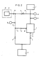
- - La figure 2 représente une installation de détection de fuite selon l'invention.
- - Figure 1 shows a known leak detection installation and which has already been described;
- - Figure 2 shows a leak detection installation according to the invention.
En se référant à la figure 2 l'installation comprend une pompe mécanique primaire 5 dont l'aspiration est reliée à une pièce à tester 9 par une conduite 13 munie d'une première vanne 2.Referring to FIG. 2, the installation comprises a primary
L'aspiration de la pompe primaire 5 est en outre reliée par une conduite 14 munie d'une seconde vanne 3 au refoulement 17 d'une pompe secondaire turbomoléculaire 7. L'aspiration de la pompe turbomoléculaire 7 est reliée par une conduite 15, munie d'une troisième vanne 4, à la pièce à tester 9. Une cellule spectrométrique 1 est reliée à l'aspiration de la pompe turbomoléculaire 7.The suction of the
Conformément à l'invention, la pompe turbomoléculaire 7 est constituée de deux étages en série et comporte entre ces deux étages un orifice d'aspiration intermédiaire 16 qui est relié, par une conduite 11 munie d'une quatrième vanne 12, à la pièce à tester 9.According to the invention, the
En outre, la pompe turbomoléculaire 7 est construite de façon à ce que son premier étage, situé dans sa demi-partie supérieure, du côté de la cellule spectrométrique 1 ait un fort taux de compression d'hélium pour diminuer le bruit de fond de l'hélium de l'air et de façon à ce que son second étage, situé dans sa demi-partie inférieure du côté de la pompe primaire 5, ait un fort débit d'azote afin de diminuer le temps de pompage de la pièce.In addition, the
Des manomètres 6, 8 et 10 permettent de mesurer les pressions à différents niveaux.
Le fonctionnement du dispositif est le suivant :The operation of the device is as follows:
Les vannes 2, 3, 4 et 12 étant fermées, on met en route la pompe primaire 5 et l'on ouvre la seconde vanne 3. Après quelques secondes, le manomètre 6 indique une pression inférieure à 1 mb et commande le démarrage de la pompe turbomoléculaire 7. Lorsque sa vitesse de rotation est atteinte, la pression indiquée par le manomètre 8 descend jusqu'à 10⁻⁶ mb.The
On peut alors allumer le filament de la cellule spectrométrique 1.We can then light the filament of the spectrometric cell 1.
La pièce à tester 9 est alors reliée à l'orifice d'entrée 18 de l'ensemble de l'installation, communément renfermée dans un coffret appelé détecteur.The part to be tested 9 is then connected to the
Le gaz traceur, tel que de l'hélium, est contenu dans une enceinte entourant la pièce 9 et représentée par des pointillés 19 sur la figure. La pièce elle-même contient de l'air à la pression atmosphérique.The tracer gas, such as helium, is contained in an enclosure surrounding the part 9 and represented by
On vide alors la pièce 9 en fermant la seconde vanne 3 et en ouvrant la première vanne 2. La pompe primaire 5 évacue l'air de la pièce 9 et lorsque le manomètre 10 indique une pression qui devient inférieure à 1 mb, on ferme alors la première vanne 2 et on ouvre la seconde vanne 3 et la quatrième vanne 12. Ainsi la pièce à tester est alors vidée par une partie de la pompe turbomoléculaire 7 et par la pompe primaire 5 reliées en série.The part 9 is then emptied by closing the second valve 3 and by opening the first valve 2. The
Ceci permet de profiter de la bonne performance de la pompe turbomoléculaire 7 dans le domaine de pression inférieure à 1 mb, alors qu'au-dessous de cette pression, la vitesse de pompage de la seule pompe primaire 5, dans le cas de l'art antérieur, est faible et diminue progressivement pour atteindre 35 % de sa valeur nominale à la pression de 10⁻² mb.This makes it possible to take advantage of the good performance of the
Lorsque la pression mesurée par la manomètre 10 atteint 10⁻² mb, on ferme alors la quatrième vanne 12 puis après quelques minutes, on ouvre lentement la troisième vanne 4 qui est une vanne d'entrée, progressive, de telle façon que la pression dans la cellule 1 indiquée par le manomètre 8 ne remonte pas au-dessus de 10⁻⁴ mb.When the pressure measured by the pressure gauge 10 reaches 10⁻² mb, the
La mesure de la fuite s'effectue lorsque la vanne 4 est grande ouverte.The leakage measurement is carried out when the valve 4 is wide open.
Ainsi, par rapport à l'art antérieur, on obtient une diminution importante du temps de pompage de la pièce à tester entre 1 mb et 10⁻² mb.Thus, compared to the prior art, a reduction is obtained significant pumping time of the part to be tested between 1 mb and 10⁻² mb.
A titre indicatif on donne les caractéristiques suivantes pour le groupe turbomoléculaire 7 constitué de deux étages en série, à la séparation desquels aboutit l'orifice 16 d'aspiration intermédiaire :
- A) Premier étage côté celule 1 :
taux de compression d'hélium : 1000
débit d'hélium : 20 l/s
débit d'azote : 50 l/s
deux solutions de construction :- 1) 8 étages turbo, dont deux rangées d'ailettes, côté aspiration, inclinées à 22°, trois à 17° et trois, côté refoulement, à 15°
- 2) 1 étage de pompe Holweck
- B) Deuxième étage côté pompe primaire 5 :
débit d'azote : 100 l/s
taux de compression d'azote : 100
taux de compression hélium : 6
solution de construction :
4 étages turbo dont deux, côté aspiration, inclinés à 35° et les deux autres, côté refoulement, à 22°.
- A) First floor on cell 1 side:
helium compression ratio: 1000
helium flow: 20 l / s
nitrogen flow: 50 l / s
two construction solutions:- 1) 8 turbo stages, including two rows of fins, suction side, inclined at 22 °, three at 17 ° and three, discharge side, at 15 °
- 2) 1 Holweck pump stage
- B) Second stage on the primary pump side 5:
nitrogen flow: 100 l / s
nitrogen compression ratio: 100
helium compression ratio: 6
construction solution:
4 turbo stages, two of which on the suction side inclined at 35 ° and the other two on the discharge side at 22 °.
Claims (2)
Priority Applications (1)
| Application Number | Priority Date | Filing Date | Title |
|---|---|---|---|
| AT87113973T ATE60441T1 (en) | 1986-09-26 | 1987-09-24 | DEVICE AND METHOD FOR DETECTING LEAKS USING A TRACE GAS. |
Applications Claiming Priority (2)
| Application Number | Priority Date | Filing Date | Title |
|---|---|---|---|
| FR8613455A FR2604522B1 (en) | 1986-09-26 | 1986-09-26 | PLOTTERY GAS LEAK DETECTION SYSTEM AND METHOD OF USE |
| FR8613455 | 1986-09-26 |
Publications (2)
| Publication Number | Publication Date |
|---|---|
| EP0268777A1 true EP0268777A1 (en) | 1988-06-01 |
| EP0268777B1 EP0268777B1 (en) | 1991-01-23 |
Family
ID=9339299
Family Applications (1)
| Application Number | Title | Priority Date | Filing Date |
|---|---|---|---|
| EP87113973A Expired - Lifetime EP0268777B1 (en) | 1986-09-26 | 1987-09-24 | Apparatus and process for detecting leaks using a tracer gas |
Country Status (8)
| Country | Link |
|---|---|
| US (1) | US4773256A (en) |
| EP (1) | EP0268777B1 (en) |
| JP (1) | JPS6396533A (en) |
| AT (1) | ATE60441T1 (en) |
| DE (1) | DE3767670D1 (en) |
| ES (1) | ES2019915B3 (en) |
| FR (1) | FR2604522B1 (en) |
| GR (1) | GR3001595T3 (en) |
Cited By (6)
| Publication number | Priority date | Publication date | Assignee | Title |
|---|---|---|---|---|
| FR2667937A1 (en) * | 1990-10-15 | 1992-04-17 | Cit Alcatel | GAS LEAK DETECTOR. |
| FR2681689A1 (en) * | 1991-09-25 | 1993-03-26 | Cit Alcatel | GAS LEAK DETECTOR. |
| FR2681688A1 (en) * | 1991-09-24 | 1993-03-26 | Cit Alcatel | GAS LEAK DETECTION INSTALLATION USING THE SNiffle technique. |
| WO1993012411A1 (en) * | 1991-12-07 | 1993-06-24 | Leybold Aktiengesellschaft | Leak indicator for vacuum systems and a method of searching for leaks in vacuum systems |
| WO1995025947A1 (en) * | 1994-03-24 | 1995-09-28 | Leybold Aktiengesellschaft | Test gas leak detector |
| CN108444651A (en) * | 2018-06-21 | 2018-08-24 | 中国核动力研究设计院 | A kind of isotope target piece helium mass spectrum leak detecting device and detection method |
Families Citing this family (32)
| Publication number | Priority date | Publication date | Assignee | Title |
|---|---|---|---|---|
| DE3865012D1 (en) * | 1988-06-01 | 1991-10-24 | Leybold Ag | PUMP SYSTEM FOR A LEAK DETECTOR. |
| DE3828588C1 (en) * | 1988-08-23 | 1989-12-07 | Alcatel Hochvakuumtechnik Gmbh, 6980 Wertheim, De | |
| DE3831258C1 (en) * | 1988-09-14 | 1989-10-12 | Alcatel Hochvakuumtechnik Gmbh, 6980 Wertheim, De | |
| FR2657164B1 (en) * | 1990-01-16 | 1992-04-03 | Cit Alcatel | LEAK DETECTION INSTALLATION WITH INTERMEDIATE HOLWECK PUMP. |
| US5076728A (en) * | 1990-04-25 | 1991-12-31 | Tracer Research Corporation | Landfill liner leak detection system and method |
| EP0464292B1 (en) * | 1990-07-06 | 1995-01-18 | Alcatel Cit | Second stage mechanical vacuum pumping unit and leak detection system using such a unit |
| JPH07111389B2 (en) * | 1990-07-10 | 1995-11-29 | アルカテル・セイテ | Mechanical pump assembly and leak detection device |
| US5167323A (en) * | 1990-08-09 | 1992-12-01 | Tomei Sangyo Co., Ltd. | Lens treating device for treating contact lens |
| US5181604A (en) * | 1990-09-14 | 1993-01-26 | Tomei Sangyo Co., Ltd. | Contact lens holder and treating device |
| DE4228313A1 (en) * | 1992-08-26 | 1994-03-03 | Leybold Ag | Counterflow leak detector with high vacuum pump |
| US5317900A (en) * | 1992-10-02 | 1994-06-07 | The Lyle E. & Barbara L. Bergquist Trust | Ultrasensitive helium leak detector for large systems |
| US5733104A (en) * | 1992-12-24 | 1998-03-31 | Balzers-Pfeiffer Gmbh | Vacuum pump system |
| US5447055A (en) * | 1993-02-09 | 1995-09-05 | Tracer Research Corporation | Automated leak detection apparatus and method |
| DE4408877A1 (en) * | 1994-03-16 | 1995-09-21 | Leybold Ag | Test gas leak detector |
| JP2655315B2 (en) * | 1994-06-29 | 1997-09-17 | 日本真空技術株式会社 | Leak detection device using compound molecular pump |
| FR2728072B1 (en) * | 1994-12-07 | 1997-01-10 | Cit Alcatel | LEAK DETECTOR |
| DE59510573D1 (en) * | 1994-12-23 | 2003-04-10 | Unaxis Balzers Ag | Gas analysis method and gas analyzer |
| FR2734633B1 (en) * | 1995-05-24 | 1997-06-20 | Cit Alcatel | INSTALLATION FOR DETECTING THE PRESENCE OF HELIUM IN A FLUID CIRCUIT |
| DE19638506A1 (en) * | 1996-09-20 | 1998-03-26 | Leybold Vakuum Gmbh | Procedure for examining a plurality of similar test objects for leaks and leak detectors suitable for carrying out this procedure |
| FR2761776B1 (en) * | 1997-04-03 | 1999-07-23 | Alsthom Cge Alcatel | GAS LEAK DETECTOR |
| JPH11230352A (en) * | 1998-02-10 | 1999-08-27 | Nec Corp | Sealed container and testing method thereof |
| US6357280B1 (en) * | 2000-06-06 | 2002-03-19 | Winbond Electronics Corp. | Leakage testing tool for a bellow of a semiconductor manufacturing machine |
| DE10156205A1 (en) * | 2001-11-15 | 2003-06-05 | Inficon Gmbh | Test gas leak detector |
| DE602004010257T2 (en) * | 2003-06-11 | 2008-10-02 | Varian, Inc., Palo Alto | METHOD AND DEVICE FOR DETECTING GREAT LEAKAGE |
| EP1860419B1 (en) | 2003-06-11 | 2014-02-26 | Agilent Technologies, Inc. | Apparatus for leak detection |
| US7168297B2 (en) * | 2003-10-28 | 2007-01-30 | Environmental Systems Products Holdings Inc. | System and method for testing fuel tank integrity |
| US6886389B1 (en) * | 2003-12-10 | 2005-05-03 | The Boeing Company | Systems and methods for detecting and locating leaks in internal pressure vessels |
| DE102005041501A1 (en) * | 2005-09-01 | 2007-03-08 | Leybold Vacuum Gmbh | Vacuum turbomolecular pump |
| US7459677B2 (en) * | 2006-02-15 | 2008-12-02 | Varian, Inc. | Mass spectrometer for trace gas leak detection with suppression of undesired ions |
| US7427751B2 (en) | 2006-02-15 | 2008-09-23 | Varian, Inc. | High sensitivity slitless ion source mass spectrometer for trace gas leak detection |
| CN104568337A (en) * | 2015-02-02 | 2015-04-29 | 上海贤日自动化设备有限公司 | Method and device for interception sampling type helium mass spectrometer leak detection |
| CN106017819B (en) * | 2016-06-24 | 2018-09-18 | 中国科学院光电研究院 | A kind of partial pressure leakage rate measurement device and method |
Citations (4)
| Publication number | Priority date | Publication date | Assignee | Title |
|---|---|---|---|---|
| DE2049117A1 (en) * | 1969-10-27 | 1971-05-06 | Sargent Welch Scientific Co | Gas leak detection system |
| EP0070341A1 (en) * | 1981-07-22 | 1983-01-26 | COMPAGNIE INDUSTRIELLE DES TELECOMMUNICATIONS CIT-ALCATEL S.A. dite: | Helium leak detector |
| DE3144503A1 (en) * | 1981-11-09 | 1983-05-26 | Cit-Alcatel GmbH, 6980 Wertheim | Mass spectrometer leak indicator |
| US4472962A (en) * | 1981-08-03 | 1984-09-25 | Balzers Aktiengesellschaft | Low pressure leak detector |
Family Cites Families (10)
| Publication number | Priority date | Publication date | Assignee | Title |
|---|---|---|---|---|
| DE1648648C3 (en) * | 1967-04-12 | 1980-01-24 | Arthur Pfeiffer-Hochvakuumtechnik Gmbh, 6330 Wetzlar | Arrangement for leak detection according to the mass spectrometer principle |
| JPS5125158A (en) * | 1974-08-26 | 1976-03-01 | Nippon Kuatsu System Co | Ryutaijikukeryono ryuryokei |
| FR2475728A1 (en) * | 1980-02-11 | 1981-08-14 | Cit Alcatel | HELIUM LEAK DETECTOR |
| DE3133781A1 (en) * | 1981-08-26 | 1983-03-10 | Leybold-Heraeus GmbH, 5000 Köln | TURBOMOLECULAR PUMP SUITABLE FOR COUNTERFLOW LEAK DETECTION |
| FR2532424A1 (en) * | 1982-08-27 | 1984-03-02 | Cit Alcatel | DEVICE FOR MEASURING AND DISPLAYING THE LEAKAGE RATE Q FOR A GAS LEAK DETECTOR |
| DE3247975A1 (en) * | 1982-12-24 | 1984-06-28 | Balzers Hochvakuum Gmbh, 6200 Wiesbaden | Method and device for detecting leaks in walls |
| FR2561771B1 (en) * | 1984-03-23 | 1986-06-27 | Cit Alcatel | METHOD FOR DEPOLLUTING A HELIUM LEAK DETECTOR AND DEVICE FOR CARRYING OUT THIS METHOD |
| US4608866A (en) * | 1985-03-13 | 1986-09-02 | Martin Marietta Corporation | Small component helium leak detector |
| US4735084A (en) * | 1985-10-01 | 1988-04-05 | Varian Associates, Inc. | Method and apparatus for gross leak detection |
| US4683749A (en) * | 1986-05-22 | 1987-08-04 | Westinghouse Electric Corp. | Process and system for detecting and measuring a tritium gas leak |
-
1986
- 1986-09-26 FR FR8613455A patent/FR2604522B1/en not_active Expired
-
1987
- 1987-09-24 ES ES87113973T patent/ES2019915B3/en not_active Expired - Lifetime
- 1987-09-24 DE DE8787113973T patent/DE3767670D1/en not_active Revoked
- 1987-09-24 AT AT87113973T patent/ATE60441T1/en not_active IP Right Cessation
- 1987-09-24 EP EP87113973A patent/EP0268777B1/en not_active Expired - Lifetime
- 1987-09-25 US US07/101,211 patent/US4773256A/en not_active Expired - Fee Related
- 1987-09-25 JP JP62240570A patent/JPS6396533A/en active Granted
-
1991
- 1991-03-12 GR GR91400314T patent/GR3001595T3/en unknown
Patent Citations (4)
| Publication number | Priority date | Publication date | Assignee | Title |
|---|---|---|---|---|
| DE2049117A1 (en) * | 1969-10-27 | 1971-05-06 | Sargent Welch Scientific Co | Gas leak detection system |
| EP0070341A1 (en) * | 1981-07-22 | 1983-01-26 | COMPAGNIE INDUSTRIELLE DES TELECOMMUNICATIONS CIT-ALCATEL S.A. dite: | Helium leak detector |
| US4472962A (en) * | 1981-08-03 | 1984-09-25 | Balzers Aktiengesellschaft | Low pressure leak detector |
| DE3144503A1 (en) * | 1981-11-09 | 1983-05-26 | Cit-Alcatel GmbH, 6980 Wertheim | Mass spectrometer leak indicator |
Cited By (12)
| Publication number | Priority date | Publication date | Assignee | Title |
|---|---|---|---|---|
| FR2667937A1 (en) * | 1990-10-15 | 1992-04-17 | Cit Alcatel | GAS LEAK DETECTOR. |
| EP0481414A1 (en) * | 1990-10-15 | 1992-04-22 | Alcatel Cit | Leak detection using tracer gas |
| US5226314A (en) * | 1990-10-15 | 1993-07-13 | Alcatel Cit | Tracer-gas leak detector |
| FR2681688A1 (en) * | 1991-09-24 | 1993-03-26 | Cit Alcatel | GAS LEAK DETECTION INSTALLATION USING THE SNiffle technique. |
| EP0534825A1 (en) * | 1991-09-24 | 1993-03-31 | Alcatel Cit | Helium leak detector |
| US5341671A (en) * | 1991-09-24 | 1994-08-30 | Alcatel Cit | Helium leak detector |
| FR2681689A1 (en) * | 1991-09-25 | 1993-03-26 | Cit Alcatel | GAS LEAK DETECTOR. |
| EP0534824A1 (en) * | 1991-09-25 | 1993-03-31 | Alcatel Cit | Tracer gas leak detector |
| WO1993012411A1 (en) * | 1991-12-07 | 1993-06-24 | Leybold Aktiengesellschaft | Leak indicator for vacuum systems and a method of searching for leaks in vacuum systems |
| US5537857A (en) * | 1991-12-07 | 1996-07-23 | Leybold Ag | Leak indicator for vacuum systems and a method of searching for leaks in vacuum systems |
| WO1995025947A1 (en) * | 1994-03-24 | 1995-09-28 | Leybold Aktiengesellschaft | Test gas leak detector |
| CN108444651A (en) * | 2018-06-21 | 2018-08-24 | 中国核动力研究设计院 | A kind of isotope target piece helium mass spectrum leak detecting device and detection method |
Also Published As
| Publication number | Publication date |
|---|---|
| GR3001595T3 (en) | 1992-11-23 |
| JPH0467141B2 (en) | 1992-10-27 |
| US4773256A (en) | 1988-09-27 |
| JPS6396533A (en) | 1988-04-27 |
| FR2604522B1 (en) | 1989-06-16 |
| FR2604522A1 (en) | 1988-04-01 |
| ES2019915B3 (en) | 1991-07-16 |
| ATE60441T1 (en) | 1991-02-15 |
| DE3767670D1 (en) | 1991-02-28 |
| EP0268777B1 (en) | 1991-01-23 |
Similar Documents
| Publication | Publication Date | Title |
|---|---|---|
| EP0268777B1 (en) | Apparatus and process for detecting leaks using a tracer gas | |
| JP2541615B2 (en) | Leakage inspection device and its operation method | |
| US4735084A (en) | Method and apparatus for gross leak detection | |
| FR2549223A1 (en) | COUNTERCURRENT LEAK DETECTOR WITH COLD TRAP | |
| EP0534825B1 (en) | Helium leak detector | |
| JPH03195935A (en) | Apparatus and method for detecting leakage | |
| JP4037954B2 (en) | Tracer gas leak detector | |
| EP0534824B1 (en) | Tracer gas leak detector | |
| US5703281A (en) | Ultra high vacuum pumping system and high sensitivity helium leak detector | |
| JP2635587B2 (en) | Device for calibrating the detector of the leak inspection device | |
| KR19980702019A (en) | Test gas leak detector | |
| EP0424830B1 (en) | Leak detecting system using tracer gas | |
| FR2734053A1 (en) | GAS LEAK DETECTOR | |
| EP0475246B1 (en) | High flow leak detector with three molecular filters | |
| JP3544989B2 (en) | Leak detector with pre-vacuum pump | |
| FR2921488A1 (en) | DEVICE AND METHOD FOR THE DETECTION OF HIGH PRESSURE PRESSURE PR GAS TRACER IN A TESTER. | |
| JP3116830B2 (en) | Helium leak detector | |
| EP1942327B1 (en) | Device and method for the quick detection of leaks | |
| FR2728072A1 (en) | LEAK DETECTOR | |
| EP3795972B1 (en) | Leak detection module and method for testing the airtightness of an object to be tested using a tracer gas | |
| CA2034143A1 (en) | Intermediate tap holweck pump leak detection apparatus | |
| JPH0519092B2 (en) | ||
| FR3121749A1 (en) | Advanced sniffing leak detection system | |
| FR3121750A1 (en) | Advanced sprinkler leak detection system | |
| JP2001050853A (en) | Method and apparatus for cleaning up helium in helium leak detector |
Legal Events
| Date | Code | Title | Description |
|---|---|---|---|
| PUAI | Public reference made under article 153(3) epc to a published international application that has entered the european phase |
Free format text: ORIGINAL CODE: 0009012 |
|
| AK | Designated contracting states |
Kind code of ref document: A1 Designated state(s): AT BE CH DE ES FR GB GR IT LI LU NL SE |
|
| 17P | Request for examination filed |
Effective date: 19881114 |
|
| RAP1 | Party data changed (applicant data changed or rights of an application transferred) |
Owner name: ALCATEL CIT |
|
| 17Q | First examination report despatched |
Effective date: 19900403 |
|
| GRAA | (expected) grant |
Free format text: ORIGINAL CODE: 0009210 |
|
| AK | Designated contracting states |
Kind code of ref document: B1 Designated state(s): AT BE CH DE ES FR GB GR IT LI LU NL SE |
|
| REF | Corresponds to: |
Ref document number: 60441 Country of ref document: AT Date of ref document: 19910215 Kind code of ref document: T |
|
| GBT | Gb: translation of ep patent filed (gb section 77(6)(a)/1977) | ||
| REF | Corresponds to: |
Ref document number: 3767670 Country of ref document: DE Date of ref document: 19910228 |
|
| ITF | It: translation for a ep patent filed |
Owner name: JACOBACCI & PERANI S.P.A. |
|
| PGFP | Annual fee paid to national office [announced via postgrant information from national office to epo] |
Ref country code: GB Payment date: 19910823 Year of fee payment: 5 |
|
| PGFP | Annual fee paid to national office [announced via postgrant information from national office to epo] |
Ref country code: GR Payment date: 19910830 Year of fee payment: 5 |
|
| PGFP | Annual fee paid to national office [announced via postgrant information from national office to epo] |
Ref country code: ES Payment date: 19910912 Year of fee payment: 5 |
|
| PGFP | Annual fee paid to national office [announced via postgrant information from national office to epo] |
Ref country code: CH Payment date: 19910918 Year of fee payment: 5 |
|
| PGFP | Annual fee paid to national office [announced via postgrant information from national office to epo] |
Ref country code: SE Payment date: 19910919 Year of fee payment: 5 |
|
| PGFP | Annual fee paid to national office [announced via postgrant information from national office to epo] |
Ref country code: NL Payment date: 19910930 Year of fee payment: 5 Ref country code: FR Payment date: 19910930 Year of fee payment: 5 Ref country code: AT Payment date: 19910930 Year of fee payment: 5 |
|
| PGFP | Annual fee paid to national office [announced via postgrant information from national office to epo] |
Ref country code: BE Payment date: 19911003 Year of fee payment: 5 |
|
| PGFP | Annual fee paid to national office [announced via postgrant information from national office to epo] |
Ref country code: LU Payment date: 19911015 Year of fee payment: 5 |
|
| PGFP | Annual fee paid to national office [announced via postgrant information from national office to epo] |
Ref country code: DE Payment date: 19911017 Year of fee payment: 5 |
|
| PLBI | Opposition filed |
Free format text: ORIGINAL CODE: 0009260 |
|
| PLBI | Opposition filed |
Free format text: ORIGINAL CODE: 0009260 |
|
| 26 | Opposition filed |
Opponent name: LEYBOLD AKTIENGESELLSCHAFT Effective date: 19911016 |
|
| 26 | Opposition filed |
Opponent name: BALZERS AKTIENGESELLSCHAFT Effective date: 19911023 Opponent name: LEYBOLD AKTIENGESELLSCHAFT Effective date: 19911016 |
|
| NLR1 | Nl: opposition has been filed with the epo |
Opponent name: BALZERS AKTIENGESELLSCHAFT Opponent name: LEYBOLD AKTIENGESELLSCHAFT |
|
| EPTA | Lu: last paid annual fee | ||
| RDAG | Patent revoked |
Free format text: ORIGINAL CODE: 0009271 |
|
| STAA | Information on the status of an ep patent application or granted ep patent |
Free format text: STATUS: PATENT REVOKED |
|
| 27W | Patent revoked |
Effective date: 19920207 |
|
| GBPR | Gb: patent revoked under art. 102 of the ep convention designating the uk as contracting state | ||
| REG | Reference to a national code |
Ref country code: CH Ref legal event code: PL |
|
| NLR2 | Nl: decision of opposition | ||
| BERE | Be: lapsed |
Owner name: ALCATEL CIT Effective date: 19920930 |
|
| REG | Reference to a national code |
Ref country code: GR Ref legal event code: MF4A Free format text: 3001595 |
|
| EUG | Se: european patent has lapsed |
Ref document number: 87113973.9 Effective date: 19920624 |