EP0268009A1 - Filter cartridge - Google Patents
Filter cartridge Download PDFInfo
- Publication number
- EP0268009A1 EP0268009A1 EP87106466A EP87106466A EP0268009A1 EP 0268009 A1 EP0268009 A1 EP 0268009A1 EP 87106466 A EP87106466 A EP 87106466A EP 87106466 A EP87106466 A EP 87106466A EP 0268009 A1 EP0268009 A1 EP 0268009A1
- Authority
- EP
- European Patent Office
- Prior art keywords
- filter
- stage
- cartridge according
- acting
- filter cartridge
- Prior art date
- Legal status (The legal status is an assumption and is not a legal conclusion. Google has not performed a legal analysis and makes no representation as to the accuracy of the status listed.)
- Granted
Links
Images
Classifications
-
- C—CHEMISTRY; METALLURGY
- C10—PETROLEUM, GAS OR COKE INDUSTRIES; TECHNICAL GASES CONTAINING CARBON MONOXIDE; FUELS; LUBRICANTS; PEAT
- C10M—LUBRICATING COMPOSITIONS; USE OF CHEMICAL SUBSTANCES EITHER ALONE OR AS LUBRICATING INGREDIENTS IN A LUBRICATING COMPOSITION
- C10M175/00—Working-up used lubricants to recover useful products ; Cleaning
- C10M175/0058—Working-up used lubricants to recover useful products ; Cleaning by filtration and centrifugation processes; apparatus therefor
-
- B—PERFORMING OPERATIONS; TRANSPORTING
- B01—PHYSICAL OR CHEMICAL PROCESSES OR APPARATUS IN GENERAL
- B01D—SEPARATION
- B01D27/00—Cartridge filters of the throw-away type
- B01D27/02—Cartridge filters of the throw-away type with cartridges made from a mass of loose granular or fibrous material
-
- B—PERFORMING OPERATIONS; TRANSPORTING
- B01—PHYSICAL OR CHEMICAL PROCESSES OR APPARATUS IN GENERAL
- B01D—SEPARATION
- B01D27/00—Cartridge filters of the throw-away type
- B01D27/04—Cartridge filters of the throw-away type with cartridges made of a piece of unitary material, e.g. filter paper
- B01D27/06—Cartridge filters of the throw-away type with cartridges made of a piece of unitary material, e.g. filter paper with corrugated, folded or wound material
-
- B—PERFORMING OPERATIONS; TRANSPORTING
- B01—PHYSICAL OR CHEMICAL PROCESSES OR APPARATUS IN GENERAL
- B01D—SEPARATION
- B01D36/00—Filter circuits or combinations of filters with other separating devices
-
- B—PERFORMING OPERATIONS; TRANSPORTING
- B01—PHYSICAL OR CHEMICAL PROCESSES OR APPARATUS IN GENERAL
- B01D—SEPARATION
- B01D37/00—Processes of filtration
- B01D37/02—Precoating the filter medium; Addition of filter aids to the liquid being filtered
- B01D37/025—Precoating the filter medium; Addition of filter aids to the liquid being filtered additives incorporated in the filter
-
- C—CHEMISTRY; METALLURGY
- C10—PETROLEUM, GAS OR COKE INDUSTRIES; TECHNICAL GASES CONTAINING CARBON MONOXIDE; FUELS; LUBRICANTS; PEAT
- C10M—LUBRICATING COMPOSITIONS; USE OF CHEMICAL SUBSTANCES EITHER ALONE OR AS LUBRICATING INGREDIENTS IN A LUBRICATING COMPOSITION
- C10M175/00—Working-up used lubricants to recover useful products ; Cleaning
-
- Y—GENERAL TAGGING OF NEW TECHNOLOGICAL DEVELOPMENTS; GENERAL TAGGING OF CROSS-SECTIONAL TECHNOLOGIES SPANNING OVER SEVERAL SECTIONS OF THE IPC; TECHNICAL SUBJECTS COVERED BY FORMER USPC CROSS-REFERENCE ART COLLECTIONS [XRACs] AND DIGESTS
- Y10—TECHNICAL SUBJECTS COVERED BY FORMER USPC
- Y10S—TECHNICAL SUBJECTS COVERED BY FORMER USPC CROSS-REFERENCE ART COLLECTIONS [XRACs] AND DIGESTS
- Y10S210/00—Liquid purification or separation
- Y10S210/05—Coalescer
-
- Y—GENERAL TAGGING OF NEW TECHNOLOGICAL DEVELOPMENTS; GENERAL TAGGING OF CROSS-SECTIONAL TECHNOLOGIES SPANNING OVER SEVERAL SECTIONS OF THE IPC; TECHNICAL SUBJECTS COVERED BY FORMER USPC CROSS-REFERENCE ART COLLECTIONS [XRACs] AND DIGESTS
- Y10—TECHNICAL SUBJECTS COVERED BY FORMER USPC
- Y10S—TECHNICAL SUBJECTS COVERED BY FORMER USPC CROSS-REFERENCE ART COLLECTIONS [XRACs] AND DIGESTS
- Y10S210/00—Liquid purification or separation
- Y10S210/06—Dehydrators
Definitions
- the innovation relates to a filter cartridge for cleaning the oil of an oil-sealed vacuum pump, which is detachably attached to the vacuum pump and contains filter materials. Filter cartridges of this type are switched on in the oil circuit of the vacuum pump and the oil constantly flows through them.
- the oils used in the vacuum pump can be mineral oils, synthetic lubricants, e.g. B. perfluorinated hydrocarbons, or the like.
- the object of the present innovation is to significantly increase the service life of oil filters without having to forego the filter concept, ie the filtering of the liquid lubricant of a vacuum pump in an exchangeable cartridge.
- the solution according to the innovation represents a simple and effective combination of a mechanical filter with a chemical depth filter for vacuum pumps.
- the service life of filter cartridges of this type is up to 100% longer than the service life previously known filter cartridges, since the combination of different filter principles in one cartridge enables improved utilization of the filter materials.
- this has the advantage of extending the service life of the liquid sealant of the vacuum pumps.
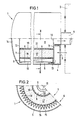
- the figures show a partial longitudinal section or a partial cross section through a filter cartridge 1 of the type according to the innovation.
- the cartridge 1 is detachably attached to the housing 2 of a vacuum pump, indicated by dashed lines.
- the way of attachment can, for. B. be designed as it is disclosed in the older DBGM 83 29 813.
- the oil flow channels located in the vacuum pump are tightly connected to the oil flow channels located in the cartridge 1.
- the liquid lubricant to be cleaned leaving the housing 2 enters an annular space 4 arranged at the end face through an opening 3 in the filter cartridge 1. From there, the lubricant flows into the annular space 5, which surrounds the concentrically arranged filter stages 6 and 7. After flowing through these filter stages, the lubricant reaches a central space 8, which is connected via line 9 to the oil circuit located in the housing 2 of the vacuum pump.
- the holder of the filter stages 6 and 7 and the described guidance of the lubricant to be cleaned is provided by a housing structure located within the cartridge 1, which includes two plates 11 and 12 arranged on the end face, among other things.
- the plate 11 is provided with the connection openings 13 between the annular spaces 4 and 5 and with the connection opening 14 between the central space 8 and the line 9.
- the plate 12 closes the central space 8 from the remaining interior 14 of the cartridge.
- a bypass valve - not shown - is usually provided in the center of the plate 12. This opens when the filter layers 6 and 7 are blocked and the pressure of the inflowing oil exceeds a certain limit pressure. Since the annular space 5 is connected to the space 14, the lubricant can flow back into the central space 8 directly and unfiltered in this case.
- the two filter stages 6 and 7 are held between the two plates 11 and 12.
- the filter stage 6 consists of a folded paper filter 15, the folds of which extend axially. Since chemically reactive substances harden the paper and thus make it brittle, the folded paper filter is also associated with a folded, sieve-like support fabric 16 which bears against the paper filter 15 on the outflow side.
- the filter material can be a filter paper suitable for mineral oils or the like, which - e.g. B. after the formation of a filter bed - is suitable for collecting solid particles down to the sub- ⁇ range. A filter material of this type also does not let through gel-like substances.
- the mechanically acting filter stage 6 is followed by the chemically acting filter stage 7.
- This filter stage 7 comprises the filter layer 17, which is made of relatively coarse activated aluminum oxide.
- a third filter stage can additionally be arranged within the chemically acting filter stage 7. This is indicated by dashed lines and designated 21.
Abstract
Die Erfindung betrifft eine Filterpatrone (1) zur Reinigung des Öls einer ölgedichteten Vakuumpumpe (2), welche lösbar an der Vakuumpumpe befestigt ist und Filtermaterialien (15, 17) enthält; um die Standzeit der Filterpatrone zu erhöhen, wird vorgeschlagen, daß eine mechanisch wirkende (6) und eine chemisch wirkende Filterstufe (7) in der Filterpatrone (1) untergebracht sind und daß die mechanisch wirkende Filterstufe der chemisch wirkenden Filterstufe - in Strömungsrichtung des zu reinigenden Öls - vorgelagert ist.The invention relates to a filter cartridge (1) for cleaning the oil of an oil-sealed vacuum pump (2), which is detachably attached to the vacuum pump and contains filter materials (15, 17); To increase the service life of the filter cartridge, it is proposed that a mechanically acting (6) and a chemically acting filter stage (7) are accommodated in the filter cartridge (1) and that the mechanically acting filter stage of the chemically active filter stage - in the flow direction of the one to be cleaned Oil - is upstream.
Description
Die Neuerung bezieht sich auf eine Filterpatrone zur Reinigung des Öls einer ölgedichteten Vakuumpumpe, welche lösbar an der Vakuumpumpe befestigt ist und Filtermaterialien enthält. Filterpatronen dieser Art sind in den Ölkreislauf der Vakuumpumpe eingeschaltet und ständig vom Öl durchströmt. Bei den in der Vakuumpumpe verwendeten Ölen kann es sich um Mineralöle, synthetische Schmiermittel, z. B. perfluorierte Kohlenwasserstoffe, oder dergleichen handeln.The innovation relates to a filter cartridge for cleaning the oil of an oil-sealed vacuum pump, which is detachably attached to the vacuum pump and contains filter materials. Filter cartridges of this type are switched on in the oil circuit of the vacuum pump and the oil constantly flows through them. The oils used in the vacuum pump can be mineral oils, synthetic lubricants, e.g. B. perfluorinated hydrocarbons, or the like.
Eine Filterpatrone der eingangs genannten Art ist aus dem DBGM 83 29 813 bekannt. Als Filtermaterial enthält die vorbekannte Filterpatrone ein Adsorptionsmittel, und zwar aktiviertes Aluminiumoxid. Dieses Filtermaterial ist dazu geeignet, Ölalterungsprodukte und polare Verunreinigungen aus dem flüssigen Schmiermittel der Vakuumpumpe zu entfernen (chemische Wirkung). Darüber hinaus ist die Körnung des Filtermaterials derart fein gewählt, daß ein Abfangen von Feststoffteilchen bis zu einer Korngröße von 1 µ möglich ist (mechanische Wirkung). Beim Einsatz der vorbekannten Filterpatronen hat sich herausgestellt, daß die Filterschicht relativ früh einen relativ hohen Widerstand aufbaut, so daß sich das in Filterpatronen der bekannten Art üblicherweise eingebaute Umgehungsventil öffnet. Bei offenem Umgehungsventil strömt das flüssige Schmiermittel ungefiltert durch den Pumpenkreislauf.A filter cartridge of the type mentioned is known from DBGM 83 29 813. The previously known filter cartridge contains an adsorbent, namely activated aluminum oxide, as the filter material. This filter material is suitable for removing oil aging products and polar impurities from the liquid lubricant of the vacuum pump (chemical effect). In addition, the grain size of the filter material is chosen so fine that it is possible to trap solid particles down to a grain size of 1 µ (mechanical effect). When using the known filter cartridges, it has been found that the filter layer builds up a relatively high resistance relatively early, so that the bypass valve usually built into filter cartridges of the known type opens. When the bypass valve is open, the liquid lubricant flows unfiltered through the pump circuit.
Der vorliegenden Neuerung liegt die Aufgabe zugrunde, die Standzeit von Ölfiltern wesentlich zu erhöhen, ohne auf das Filterkonzept, d. h., die Filtrierung des flüssigen Schmiermittels einer Vakuumpumpe in einer Wechselpatrone, verzichten zu müssen.The object of the present innovation is to significantly increase the service life of oil filters without having to forego the filter concept, ie the filtering of the liquid lubricant of a vacuum pump in an exchangeable cartridge.
Neuerungsgemäß wird diese Aufgabe dadurch gelöst, daß in der Filterpatrone mindestens zwei Filterstufen mit unterschiedlichen Eigenschaften untergebracht sind. Zweckmäßigerweise sind eine mechanisch wirkende und eine chemisch wirkende Filterstufe vorhanden, und die mechanisch wirkende Filterstufe ist der chemisch wirkenden Filterstufe - in Strömungsrichtung des zu reinigenden Öls - vorgelagert.According to the invention, this object is achieved in that at least two filter stages with different properties are accommodated in the filter cartridge. A mechanically acting and a chemically acting filter stage are expediently present, and the mechanically acting filter stage is located upstream of the chemically acting filter stage - in the flow direction of the oil to be cleaned.
Diese Neuerung beruht auf der Erkenntis, daß die Ursache für den relativ frühen Aufbau des hohen Widerstandes über der Filterschicht der vorbekannten Filterpatrone Feststoffteilchen und Gele sind, die das wegen der relativ kleinen Körnung dicht gepackte Filtermaterial zusetzen. Durch die neuerungsgemäße Ausrüstung der Filterpatrone mit zwei Filterstufen mit unterschiedlichen Eigenschaften besteht die Möglichkeit, eine mechanisch wirkende und eine chemisch wirkende Filterstufe hintereinander anzuordnen und somit die chemisch wirkende Filterstufe von der Aufgabe, auch Feststoffteilchen abfangen zu müssen, zu befreien. Die Körnung der vorzugsweise in Form eines Granulates aus aktiviertem Aluminiumoxid vorliegenden, chemisch wirksamen Filterschicht kann relativ grob, z. B. von 0, 5 bis 5 mm, vorzugsweise 1 bis 3 mm, gewählt werden. Die chemische Wirksamkeit dieser Filterschicht ist dadurch gegenüber einer Filterschicht mit kleinerer Körnung nicht beeinträchtigt. Die dieser chemisch wirkenden Filterschicht vorgelagerte mechanisch wirkende Filterstufe, welche zweckmäßigerweise als Papierfilter ausgebildet ist, übernimmt die Abscheidung von Feststoffteilchen und Gelen, welche somit die chemisch wirkende Filterschicht nicht mehr belasten. Neben Aluminiumoxid können auch andere Ad- oder Absorbenten,wie Bleicherde, verwendet werden.This innovation is based on the finding that the reason for the relatively early build-up of the high resistance over the filter layer of the previously known filter cartridge is solid particles and gels, which clog the filter material because of the relatively small particle size. Due to the new equipment of the filter cartridge with two filter stages with different properties, it is possible to arrange a mechanically acting and a chemically acting filter stage one after the other and thus to free the chemically acting filter stage from the task of also having to trap solid particles. The grain size of the chemically active filter layer, preferably in the form of granules of activated aluminum oxide, can be relatively coarse, e.g. B. from 0.5 to 5 mm, preferably 1 to 3 mm. This does not affect the chemical effectiveness of this filter layer compared to a filter layer with a smaller grain size. The mechanically acting filter stage upstream of this chemically active filter layer, which is expediently designed as a paper filter, takes over the separation of solid particles and gels, which therefore no longer burden the chemically active filter layer. In addition to aluminum oxide, other adsorbents or absorbents, such as bleaching earth, can also be used.
Die neuerungsgemäße Lösung stellt eine einfache und für Vakuumpumpen effektive Kombination eines mechanischen Filters mit einem chemischen Tiefenfilter dar. Die Standzeit vonFilterpatronen dieser Art ist je nach Filtrationsaufgabe um bis zu 100 % höher als die Standzeit vorbekannter Filterpatronen, da die Vereinigung verschiedener Filterprinzipien in einer Patrone eine verbesserte Ausnutzung der Filtermaterialien ermöglicht. Gleichzeitig ist damit der Vorteil einer Standzeitverlängerung der flüssigen Dichtmittel de r Vakuumpumpen verbunden.The solution according to the innovation represents a simple and effective combination of a mechanical filter with a chemical depth filter for vacuum pumps. Depending on the filtration task, the service life of filter cartridges of this type is up to 100% longer than the service life previously known filter cartridges, since the combination of different filter principles in one cartridge enables improved utilization of the filter materials. At the same time, this has the advantage of extending the service life of the liquid sealant of the vacuum pumps.
Weitere Vorteile und Einzelheiten der Neuerung sollen anhand eines in den Figuren 1 und 2 dargestellten Ausführungsbeispieles erläutert werden.Further advantages and details of the innovation will be explained with reference to an embodiment shown in Figures 1 and 2.
Die Figuren zeigen einen Teillängsschnitt bzw. einen Teilquerschnitt durch eine Filterpatrone 1 der neuerungsgemäßen Art. Die Patrone 1 ist lösbar an dem gestrichelt angedeuteten Gehäuse 2 einer Vakuumpumpe befestigt. Die Art und Weise der Befestigung kann z. B. derart gestaltet sein, wie es im älteren DBGM 83 29 813 offenbart ist. Gleichzeitig mit der Befestigung der Filterpatrone 1 auf dem Gehäuse 2 der Vakuumpumpe erfolgt die dichte Verbindung der in der Vakuumpumpe befindlichen Ölströmungskanäle mit den in der Patrone 1 befindlichen Ölströmungskanälen.The figures show a partial longitudinal section or a partial cross section through a
Beim dargestellten Ausführungsbeispiel tritt das das Gehäuse 2 verlassende, zu reinigende flüssige Schmiermittel durch eine stirnseitige Öffnung 3 in der Filterpatrone 1 in einen stirnseitig angeordneten Ringraum 4 ein. Von dort aus strömt das Schmiermittel in den Ringraum 5, der die konzentrisch angeordneten Filterstufen 6 und 7 umgibt. Nach dem Durchströmen dieser Filterstufen gelangt das Schmiermittel in einen zentralen Raum 8, der über die Leitung 9 mit dem im Gehäuse 2 der Vakuumpumpe befindlichen Ölkreislauf verbunden ist.In the exemplary embodiment shown, the liquid lubricant to be cleaned leaving the
Der Halterung der Filterstufen 6 und 7 und der beschriebenen Führung des zu reinigenden Schmiermittels dient eine innerhalb der Patrone 1 befindliche Gehäusestruktur, die unter anderem zwei stirnseitig angeordnete Platten 11 und 12 umfaßt. Die Platte 11 ist mit den Verbindungsöffnungen 13 zwischen den Ringräumen 4 und 5 und mit der Verbindungsöffnung 14 zwischen dem Zentralraum 8 und der Leitung 9 versehen. Die Platte 12 schließt den Zentraraum 8 zum übrigen Innenraum 14 der Patrone ab. Im Zentrum der Platte 12 ist üblicherweise ein - nicht dargestelltes - Umgehungsventil vorgesehen. Dieses öffnet, wenn die Filterschichten 6 und 7 blockiert sind und der Druck des zuströmenden Öls einen bestimmten Grenzdruck übersteigt. Da der Ringraum 5 mit dem Raum 14 verbunden ist, kann das Schmiermittel in diesem Fall direkt und ungefiltert in den Zentralraum 8 zurückströmen.The holder of the
Zwischen den beiden Platten 11 und 12 sind die beiden Filterstufen 6 und 7 gehaltert. Die Filterstufe 6 besteht aus einem gefalteten Papierfilter 15, dessen Falten sich axial erstrecken. Da chemisch reaktive Substanzen das Papier aushärten und damit brüchig werden lassen, ist dem gefalteten Papierfilter ein ebenfalls gefaltetes, siebartiges Stützgewebe 16 zugeordnet, das dem Papierfilter 15 abströmseitig anliegt. Das Filtermaterial kann ein für Mineralöle oder dergleichen geeignetes Filterpapier sein, das - z. B. nach der Bildung eines Filterbettes - dazu geeignet ist, Feststoffteilchen bis in den Sub-µ-Bereich aufzufangen. Auch gelartige Substanzen läßt ein Filtermaterial dieser Art nicht durch.The two
An die mechanisch wirkende Filterstufe 6 schließt sich die chemisch wirkende Filterstufe 7 an. Diese Filterstufe 7 umfaßt die Filterschicht 17, die aus relativ grobkörnigem aktivierten Aluminiumoxid besteht. Zur Stützung des Filtergranulats dienen die konzentrischen Lochmaterial-Wandungen 18 und 19, die sich zwischen den beiden stirnseitig angeordneten Platten 11 und 12 erstrecken.The mechanically
Bei einer Variante der in den Figuren 1 und 2 dargestellten Ausführungsform einer neuerungsgemäßen Filterpatrone kann zusätzlich noch eine dritte Filterstufe innerhalb der chemisch wirkenden Filterstufe 7 angeordnet sein. Diese ist gestrichelt angedeutet und mit 21 bezeichnet. Sie kann z. B. ebenfalls als Papierfilter ausgebildet sein, das in der Lage ist, besonders feine Feststoffpartikel (kleiner als 1 µ) zurückzuhalten. In diesem Fall besteht die Möglichkeit, die Durchlässigkeit des Filterpapiers 15 etwas gröber zu wählen. In a variant of the embodiment of a filter cartridge according to the invention shown in FIGS. 1 and 2, a third filter stage can additionally be arranged within the chemically
Claims (10)
dadurch gekennzeichnet, daß mindestens zwei Filterstufen (6,7) mit unterschiedlichen Eigenschaften in der Patrone (1) untergebracht sind.1. filter cartridge for cleaning the oil of an oil-sealed vacuum pump, which is detachably attached to the vacuum pump and contains filter materials,
characterized in that at least two filter stages (6, 7) with different properties are accommodated in the cartridge (1).
Applications Claiming Priority (2)
| Application Number | Priority Date | Filing Date | Title |
|---|---|---|---|
| DE8628284U | 1986-10-23 | ||
| DE8628284U DE8628284U1 (en) | 1986-10-23 | 1986-10-23 |
Publications (2)
| Publication Number | Publication Date |
|---|---|
| EP0268009A1 true EP0268009A1 (en) | 1988-05-25 |
| EP0268009B1 EP0268009B1 (en) | 1993-08-25 |
Family
ID=6799509
Family Applications (1)
| Application Number | Title | Priority Date | Filing Date |
|---|---|---|---|
| EP87106466A Expired - Lifetime EP0268009B1 (en) | 1986-10-23 | 1987-05-05 | Filter cartridge |
Country Status (5)
| Country | Link |
|---|---|
| US (1) | US4886599A (en) |
| EP (1) | EP0268009B1 (en) |
| JP (1) | JP2588909B2 (en) |
| DE (2) | DE8628284U1 (en) |
| ES (1) | ES2042517T3 (en) |
Cited By (2)
| Publication number | Priority date | Publication date | Assignee | Title |
|---|---|---|---|---|
| DE19608589A1 (en) * | 1996-03-06 | 1997-09-11 | Mann & Hummel Filter | filter |
| CN112496854A (en) * | 2020-11-26 | 2021-03-16 | 厦门艺琉如机械有限公司 | Lubricating system waste oil recovery device for gantry milling machine |
Families Citing this family (31)
| Publication number | Priority date | Publication date | Assignee | Title |
|---|---|---|---|---|
| GB2222534B (en) * | 1988-09-09 | 1992-11-25 | Process Scient Innovations | Filter assembly and cartridge therefor |
| EP0387235A1 (en) * | 1989-01-24 | 1990-09-12 | Ferdinand Berger | Process for the recuperation of spent motor vehicle oils, and device for carrying out same |
| US5069799A (en) * | 1989-09-07 | 1991-12-03 | Exxon Research & Engineering Company | Method for rejuvenating lubricating oils |
| US5238474A (en) * | 1990-10-19 | 1993-08-24 | Donaldson Company, Inc. | Filtration arrangement |
| DE4033172C1 (en) * | 1990-10-19 | 1992-05-21 | Maschinenfabrik Reinhausen Gmbh, 8400 Regensburg, De | |
| US5288299A (en) * | 1991-02-22 | 1994-02-22 | Ebara Corporation | Exhaust gas treating apparatus |
| DE4214694A1 (en) * | 1992-05-02 | 1993-11-04 | Reinhard Weber | Long life filter esp. oil filter - has regions of differing pore width |
| US5374354A (en) * | 1992-09-24 | 1994-12-20 | Sundstrand Corporation | Method of increasing service life of oil and a filter in an integrated drive generator or constant speed drive and improved oil filter for use therein |
| US5552040A (en) * | 1992-09-24 | 1996-09-03 | Sundstrand Corporation | Method of increasing service life of oil and a filter for use therewith |
| US5580451A (en) * | 1995-05-01 | 1996-12-03 | Automotive Fluid Systems, Inc. | Air conditioning refrigerant fluid dryer assembly |
| USD404807S (en) * | 1996-07-11 | 1999-01-26 | Donaldson Company, Inc. | Filter sleeve |
| US5858044A (en) * | 1996-07-11 | 1999-01-12 | Donaldson Company, Inc. | Filter arrangement including removable filter with first and second media secured together |
| US6007608A (en) * | 1998-07-10 | 1999-12-28 | Donaldson Company, Inc. | Mist collector and method |
| US6110248A (en) * | 1998-08-31 | 2000-08-29 | Shop Vac Corporation | Dual filter assembly for a vacuum cleaner |
| US6113663A (en) * | 1998-11-10 | 2000-09-05 | Shop Vac Corporation | Vacuum cleaner having a dual filter assembly |
| US6422396B1 (en) | 1999-09-16 | 2002-07-23 | Kaydon Custom Filtration Corporation | Coalescer for hydrocarbons containing surfactant |
| US6379564B1 (en) * | 2000-05-08 | 2002-04-30 | Ronald Paul Rohrbach | Multi-stage fluid filter, and methods of making and using same |
| US7182863B2 (en) * | 2000-05-08 | 2007-02-27 | Honeywell International, Inc. | Additive dispersing filter and method of making |
| JP2003532516A (en) * | 2000-05-08 | 2003-11-05 | ハネウェル・インターナショナル・インコーポレーテッド | Oil filter |
| US7291264B2 (en) * | 2000-05-08 | 2007-11-06 | Honeywell International, Inc. | Staged oil filter incorporating additive-releasing particles |
| US7018531B2 (en) * | 2001-05-30 | 2006-03-28 | Honeywell International Inc. | Additive dispensing cartridge for an oil filter, and oil filter incorporating same |
| US7118673B2 (en) * | 2001-07-17 | 2006-10-10 | Hti Filtration Corporation | Filter for oil containing adhesive contaminants |
| GB2390825B (en) * | 2002-06-07 | 2005-08-17 | Baldwin Filters Inc | Environmentally friendly acid neutralizing cartridge |
| US7370701B2 (en) * | 2004-06-30 | 2008-05-13 | Halliburton Energy Services, Inc. | Wellbore completion design to naturally separate water and solids from oil and gas |
| US7429332B2 (en) * | 2004-06-30 | 2008-09-30 | Halliburton Energy Services, Inc. | Separating constituents of a fluid mixture |
| US7931817B2 (en) * | 2008-02-15 | 2011-04-26 | Honeywell International Inc. | Additive dispensing device and a thermally activated additive dispensing filter having the additive dispensing device |
| US9162167B2 (en) | 2012-04-26 | 2015-10-20 | Aquamira Technologies, Inc. | Simplified filter |
| JP6057541B2 (en) * | 2012-05-07 | 2017-01-11 | トヨタ紡織株式会社 | Oil deterioration control device |
| US9623350B2 (en) | 2013-03-01 | 2017-04-18 | Fram Group Ip Llc | Extended-life oil management system and method of using same |
| JP6772792B2 (en) * | 2016-11-30 | 2020-10-21 | トヨタ紡織株式会社 | Internal combustion engine tubular air cleaner |
| DE102019122034A1 (en) * | 2018-09-11 | 2020-03-12 | Mann+Hummel Gmbh | Filter element with a receiving space containing a desiccant and fluid filter |
Citations (6)
| Publication number | Priority date | Publication date | Assignee | Title |
|---|---|---|---|---|
| BE637246A (en) * | 1963-07-19 | |||
| DE1786334A1 (en) * | 1968-09-17 | 1971-12-23 | Zimmer Cornelius P | Oil bypass filter Ultra filter |
| DE2616954A1 (en) * | 1975-06-02 | 1977-02-24 | Schumacher Nihon Kk | Dual purpose filter cartridge with adsorption section - constructed as concentric annuli with perforated walls and means for recharging the adsorbent |
| GB2012178A (en) * | 1978-01-11 | 1979-07-25 | Purolator Inc | Fluid filters |
| FR2414940A1 (en) * | 1978-01-20 | 1979-08-17 | App Regeneration Economiqu | Filter cartridge for the filtration of liquids - has second filter surface downstream of liq. being filtered |
| DE8329813U1 (en) * | 1984-01-05 | Leybold-Heraeus GmbH, 5000 Köln | Oil-sealed vacuum pump with oil filter |
Family Cites Families (6)
| Publication number | Priority date | Publication date | Assignee | Title |
|---|---|---|---|---|
| GB950333A (en) * | 1961-05-17 | 1964-02-26 | Winslow Engineering And Mfg Co | Improvements in filters and separators |
| US3662893A (en) * | 1969-08-25 | 1972-05-16 | Wix Corp | Filter cartridge |
| US3836005A (en) * | 1973-09-13 | 1974-09-17 | Gen Motors Corp | Dry cleaning filter element assembly |
| US4231768A (en) * | 1978-09-29 | 1980-11-04 | Pall Corporation | Air purification system and process |
| US4372847A (en) * | 1980-06-23 | 1983-02-08 | Chicago Rawhide Manufacturing Company | Fuel filter assembly and cartridge |
| US4557829A (en) * | 1984-06-13 | 1985-12-10 | Champion Laboratories, Inc. | Two stage filter |
-
1986
- 1986-10-23 DE DE8628284U patent/DE8628284U1/de not_active Expired
-
1987
- 1987-05-05 ES ES87106466T patent/ES2042517T3/en not_active Expired - Lifetime
- 1987-05-05 EP EP87106466A patent/EP0268009B1/en not_active Expired - Lifetime
- 1987-05-05 DE DE87106466T patent/DE3787152D1/en not_active Expired - Fee Related
- 1987-10-22 JP JP62265530A patent/JP2588909B2/en not_active Expired - Lifetime
- 1987-10-23 US US07/111,592 patent/US4886599A/en not_active Expired - Fee Related
Patent Citations (6)
| Publication number | Priority date | Publication date | Assignee | Title |
|---|---|---|---|---|
| DE8329813U1 (en) * | 1984-01-05 | Leybold-Heraeus GmbH, 5000 Köln | Oil-sealed vacuum pump with oil filter | |
| BE637246A (en) * | 1963-07-19 | |||
| DE1786334A1 (en) * | 1968-09-17 | 1971-12-23 | Zimmer Cornelius P | Oil bypass filter Ultra filter |
| DE2616954A1 (en) * | 1975-06-02 | 1977-02-24 | Schumacher Nihon Kk | Dual purpose filter cartridge with adsorption section - constructed as concentric annuli with perforated walls and means for recharging the adsorbent |
| GB2012178A (en) * | 1978-01-11 | 1979-07-25 | Purolator Inc | Fluid filters |
| FR2414940A1 (en) * | 1978-01-20 | 1979-08-17 | App Regeneration Economiqu | Filter cartridge for the filtration of liquids - has second filter surface downstream of liq. being filtered |
Cited By (2)
| Publication number | Priority date | Publication date | Assignee | Title |
|---|---|---|---|---|
| DE19608589A1 (en) * | 1996-03-06 | 1997-09-11 | Mann & Hummel Filter | filter |
| CN112496854A (en) * | 2020-11-26 | 2021-03-16 | 厦门艺琉如机械有限公司 | Lubricating system waste oil recovery device for gantry milling machine |
Also Published As
| Publication number | Publication date |
|---|---|
| ES2042517T3 (en) | 1993-12-16 |
| JP2588909B2 (en) | 1997-03-12 |
| EP0268009B1 (en) | 1993-08-25 |
| US4886599A (en) | 1989-12-12 |
| JPS63123410A (en) | 1988-05-27 |
| DE3787152D1 (en) | 1993-09-30 |
| DE8628284U1 (en) | 1986-12-18 |
Similar Documents
| Publication | Publication Date | Title |
|---|---|---|
| EP0268009B1 (en) | Filter cartridge | |
| EP0951329A1 (en) | Filter, in particular for the lubricating oil of an internal combustion engine | |
| EP0656223A1 (en) | Backwashfilter | |
| DE2626008A1 (en) | AIR CLEANER | |
| DE1134785B (en) | Filter and coalescer device for liquid hydrocarbons | |
| DE60003202T2 (en) | METHOD AND FILTER FOR FILTERING A SLUDGE | |
| DE19837569B4 (en) | Method for cleaning filter candles of a candle filter | |
| EP1775007A2 (en) | Cartridge for the purification of compressed air from the compressed air producing systems of a motor vehicle | |
| EP4094819A1 (en) | Filter element | |
| DE102017003577A1 (en) | Apparatus for treating fluid | |
| EP0577941B1 (en) | Backwash liquid filter | |
| DE102014000903A1 (en) | Filter and coalescing element and associated media layer and filter device | |
| DE3733306C1 (en) | Backwash filter | |
| DE102006018725B4 (en) | Plant for filtering cooling or processing media for cutting, grinding and erosion processes | |
| DE1058021B (en) | Liquid filter with several filter bodies arranged one inside the other | |
| DE1436251A1 (en) | Arrangement for filters for liquids | |
| EP0024514B1 (en) | Filter arrangement for the filtration of liquids, especially lubricating oil | |
| DE4401116A1 (en) | Filter candle | |
| EP0729419B1 (en) | Drying cartridge for air drying installations, especially for vehicle air-brake systems | |
| EP0810018B1 (en) | Backwash filtering device and filter candles | |
| DE19518575C2 (en) | Device and method for backwashing candle or precoat filters | |
| DE2616954A1 (en) | Dual purpose filter cartridge with adsorption section - constructed as concentric annuli with perforated walls and means for recharging the adsorbent | |
| EP3211205A1 (en) | Cleaning module, filter element and filter system | |
| EP1093392A1 (en) | Multi-stage filtering device | |
| DE3135813C2 (en) | Filtration device for series double fine filtration of liquids, especially diesel engine lubricating oil |
Legal Events
| Date | Code | Title | Description |
|---|---|---|---|
| PUAI | Public reference made under article 153(3) epc to a published international application that has entered the european phase |
Free format text: ORIGINAL CODE: 0009012 |
|
| AK | Designated contracting states |
Kind code of ref document: A1 Designated state(s): CH DE ES FR GB LI |
|
| 17P | Request for examination filed |
Effective date: 19881111 |
|
| 17Q | First examination report despatched |
Effective date: 19900924 |
|
| GRAA | (expected) grant |
Free format text: ORIGINAL CODE: 0009210 |
|
| AK | Designated contracting states |
Kind code of ref document: B1 Designated state(s): CH DE ES FR GB LI |
|
| GBT | Gb: translation of ep patent filed (gb section 77(6)(a)/1977) |
Effective date: 19930823 |
|
| REF | Corresponds to: |
Ref document number: 3787152 Country of ref document: DE Date of ref document: 19930930 |
|
| REG | Reference to a national code |
Ref country code: ES Ref legal event code: FG2A Ref document number: 2042517 Country of ref document: ES Kind code of ref document: T3 |
|
| ET | Fr: translation filed | ||
| PLBE | No opposition filed within time limit |
Free format text: ORIGINAL CODE: 0009261 |
|
| STAA | Information on the status of an ep patent application or granted ep patent |
Free format text: STATUS: NO OPPOSITION FILED WITHIN TIME LIMIT |
|
| 26N | No opposition filed | ||
| PGFP | Annual fee paid to national office [announced via postgrant information from national office to epo] |
Ref country code: FR Payment date: 19970411 Year of fee payment: 11 |
|
| PGFP | Annual fee paid to national office [announced via postgrant information from national office to epo] |
Ref country code: GB Payment date: 19970417 Year of fee payment: 11 |
|
| PGFP | Annual fee paid to national office [announced via postgrant information from national office to epo] |
Ref country code: DE Payment date: 19970423 Year of fee payment: 11 |
|
| PGFP | Annual fee paid to national office [announced via postgrant information from national office to epo] |
Ref country code: CH Payment date: 19970501 Year of fee payment: 11 |
|
| PGFP | Annual fee paid to national office [announced via postgrant information from national office to epo] |
Ref country code: ES Payment date: 19970513 Year of fee payment: 11 |
|
| PG25 | Lapsed in a contracting state [announced via postgrant information from national office to epo] |
Ref country code: GB Free format text: LAPSE BECAUSE OF NON-PAYMENT OF DUE FEES Effective date: 19980505 |
|
| PG25 | Lapsed in a contracting state [announced via postgrant information from national office to epo] |
Ref country code: ES Free format text: LAPSE BECAUSE OF NON-PAYMENT OF DUE FEES Effective date: 19980506 |
|
| PG25 | Lapsed in a contracting state [announced via postgrant information from national office to epo] |
Ref country code: LI Free format text: LAPSE BECAUSE OF NON-PAYMENT OF DUE FEES Effective date: 19980531 Ref country code: FR Free format text: LAPSE BECAUSE OF NON-PAYMENT OF DUE FEES Effective date: 19980531 Ref country code: CH Free format text: LAPSE BECAUSE OF NON-PAYMENT OF DUE FEES Effective date: 19980531 |
|
| GBPC | Gb: european patent ceased through non-payment of renewal fee |
Effective date: 19980505 |
|
| REG | Reference to a national code |
Ref country code: CH Ref legal event code: PL |
|
| PG25 | Lapsed in a contracting state [announced via postgrant information from national office to epo] |
Ref country code: DE Free format text: LAPSE BECAUSE OF NON-PAYMENT OF DUE FEES Effective date: 19990302 |
|
| REG | Reference to a national code |
Ref country code: FR Ref legal event code: ST |
|
| REG | Reference to a national code |
Ref country code: ES Ref legal event code: FD2A Effective date: 20000403 |