EP0267953B1 - Differential gear - Google Patents
Differential gear Download PDFInfo
- Publication number
- EP0267953B1 EP0267953B1 EP87903829A EP87903829A EP0267953B1 EP 0267953 B1 EP0267953 B1 EP 0267953B1 EP 87903829 A EP87903829 A EP 87903829A EP 87903829 A EP87903829 A EP 87903829A EP 0267953 B1 EP0267953 B1 EP 0267953B1
- Authority
- EP
- European Patent Office
- Prior art keywords
- differential gear
- shaft
- wheel
- gear
- differential
- Prior art date
- Legal status (The legal status is an assumption and is not a legal conclusion. Google has not performed a legal analysis and makes no representation as to the accuracy of the status listed.)
- Expired
Links
- 230000005540 biological transmission Effects 0.000 description 2
- 230000000295 complement effect Effects 0.000 description 1
- 230000003247 decreasing effect Effects 0.000 description 1
- 230000000694 effects Effects 0.000 description 1
- 230000014759 maintenance of location Effects 0.000 description 1
- 238000000034 method Methods 0.000 description 1
Images


Classifications
-
- F—MECHANICAL ENGINEERING; LIGHTING; HEATING; WEAPONS; BLASTING
- F16—ENGINEERING ELEMENTS AND UNITS; GENERAL MEASURES FOR PRODUCING AND MAINTAINING EFFECTIVE FUNCTIONING OF MACHINES OR INSTALLATIONS; THERMAL INSULATION IN GENERAL
- F16H—GEARING
- F16H48/00—Differential gearings
- F16H48/20—Arrangements for suppressing or influencing the differential action, e.g. locking devices
- F16H48/22—Arrangements for suppressing or influencing the differential action, e.g. locking devices using friction clutches or brakes
-
- F—MECHANICAL ENGINEERING; LIGHTING; HEATING; WEAPONS; BLASTING
- F16—ENGINEERING ELEMENTS AND UNITS; GENERAL MEASURES FOR PRODUCING AND MAINTAINING EFFECTIVE FUNCTIONING OF MACHINES OR INSTALLATIONS; THERMAL INSULATION IN GENERAL
- F16H—GEARING
- F16H48/00—Differential gearings
- F16H48/06—Differential gearings with gears having orbital motion
- F16H48/08—Differential gearings with gears having orbital motion comprising bevel gears
-
- F—MECHANICAL ENGINEERING; LIGHTING; HEATING; WEAPONS; BLASTING
- F16—ENGINEERING ELEMENTS AND UNITS; GENERAL MEASURES FOR PRODUCING AND MAINTAINING EFFECTIVE FUNCTIONING OF MACHINES OR INSTALLATIONS; THERMAL INSULATION IN GENERAL
- F16H—GEARING
- F16H48/00—Differential gearings
- F16H48/06—Differential gearings with gears having orbital motion
- F16H48/10—Differential gearings with gears having orbital motion with orbital spur gears
-
- F—MECHANICAL ENGINEERING; LIGHTING; HEATING; WEAPONS; BLASTING
- F16—ENGINEERING ELEMENTS AND UNITS; GENERAL MEASURES FOR PRODUCING AND MAINTAINING EFFECTIVE FUNCTIONING OF MACHINES OR INSTALLATIONS; THERMAL INSULATION IN GENERAL
- F16H—GEARING
- F16H48/00—Differential gearings
- F16H48/20—Arrangements for suppressing or influencing the differential action, e.g. locking devices
- F16H48/27—Arrangements for suppressing or influencing the differential action, e.g. locking devices using internally-actuatable fluid pressure, e.g. internal pump types
Definitions
- the present invention concerns a differential gear having a differential gear housing driveable for rotation, in said housing, rotating therewith, being arranged the shafts of differential planet wheels freely rotatable per se and side wheels meshing therewith, said side wheels being freely rotatably journalled relative to the differential gear housing and being in rotational connection with a respective shaft rotatable relative to the differential gear housing.
- differential gear is commonly used in motor vehicles to distribute the drive power from the drive engine to two driving wheels.
- the differential gear housing carries a crown wheel meshing with a differential drive pinion which in turn is driven by the motor.
- the side wheels are directly connected to a respective output shaft carrying a driving wheel.
- Known differential gears have the serious drawback that they function as intended only when the driving wheels are in full frictional engagement with the ground. As soon as a driving wheel looses its full engagement, the driving capacity of the other driving wheel is correspondingly decreased so as to entirely cease when the first driving wheel has lost all frictional contact with the ground. This peculiarity of conventional differential gears involves great risks in skid situations, particularly in connection with the so called secondary skid.
- a secondary skid occurs after a primary skid when both driving wheels, according to the above, have lost their driving capacity.
- the driving wheel leading in the direction of skidding has at least some engagement in the direction of traction, while the other driving wheel is more or less raised from the ground.
- the differential gear then transfers substantially all drive power to the easiest driveable driving wheel, viz. the raised one, in which is built up a large mass energy.
- the object of the present invention is to provide a differential gear which makes it possible to completely freely distribute input power between the two output shafts of the gear, i.e., to choose everything from a pure differential lock function to a function where the shafts rotate oppositely.
- the differential gear of the present invention is basicly a conventional differential gear which is completed with at least one planetary gear. More precisely, it is a differential gear, at least one output wheel (side wheel) of which carries the planet wheel holders of a planetary gear, the sun wheel of which is freely rotatably journalled relative to the shaft of the side wheel and the ring wheel of which is rigidly connected to the differential gear housing.
- the differential gear can be so arranged that the sun wheel is connected to a control shaft in the shape of a hollow shaft which is journalled on the shaft of the side wheel, which, in this case, is one output shaft of the gear.
- Control of the gear is accomplished in that the control shaft and therewith the sun wheel is imparted a rotational speed differing from that of the output shaft, or, the differential gear housing.
- the control shaft is separately driveable (active control), or, brakeable (passive control) relative to the differential gear housing, or, the output shaft.
- the differential gear according to the invention can be arranged such that the sun wheel is connected to an output shaft, while the shaft of the side wheel is control shaft in the shape of a hollow shaft journalled around the output shaft. Control is achieved in that the control shaft and with it the planet wheel holder and the side wheel is given a rotational speed differing from that of the output shaft (active or passive control as above).
- Control of the gear by actuating the control shaft in both embodiments results in a rotational speed difference between the output shafts. Unactuated it operates like an entirely ordinary differential gear.
- fig. 1 shows an axial section through a gear made according to the preferred embodiment
- fig. 2 shows schematically the same gear
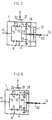
- fig. 3 shows in the same manner the same gear adapted for passive control
- fig. 4 shows in the same manner the same gear adapted for alternative passive control
- fig. 5 shows in the same manner the same gear adapted for active control
- fig. 6 shows schematically the gear according to the second embodiment
- fig. 7 shows schematically a differential gear having two planetary gears
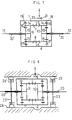
- fig. 8 shows schematically a passively controllable gear according to fig. 7, and
- fig. 9 shows an actively controllable gear according to fig. 7.
- a differential gear housing 1 in the example according to fig. 1 including several assembled parts 2, 3 and 4, is arranged a plurality of radial shafts, of which are shown two shafts 5 and 6._ These shafts freely rotatably carries the planetary wheels 7 and 8, respectively, of the differential gear, which are meshing with the side wheels 9 and 10, respectively, of the gear.
- the side wheels 9 and 10 are freely rotatable relative to the housing 1 and by means of splines non-rotationally connected to a respective output shaft 11 and 12 extending out of the housing 1 and being rotatable relative thereto.
- the part 4 of the housing 1 is provided with flanges 13 for mounting a non-shown crown wheel by which the housing 1 is driveable in rotation.
- the differential gear now described, in all essential is a conventional differential gear the gear-wheels of which are permanently meshing with each other.
- differential gear described above having differential planetary wheels with radial axes
- the invention is as well applicable to any other kind of differential gear, e.g. such having differential planetary wheels with axial axes.
- At least one of the side wheels of the gear is adapted as a holder for the planet wheels of a planetary gear.
- the side wheel 10 is planet wheel holder for a plurality of planet wheels, of which are shown two planet wheels 16 and 17 freely rotatable about shafts 14 and 15.
- the differential gear housing is connected to the ring wheel of the planetary gear.
- a ring wheel 18 is pressed into the part 4 of the housing 1 and is rotatable with the housing.
- the sun wheel of the planetary gear is rotatable relative to the shaft connected to the side wheel in question. In the example according to fig.
- the sun wheel 19 of the planetary gear is arranged in the end of a hollow shaft 20 which is rotatable about the output shaft 12 connected to the side wheel 10.
- the planet wheels 16 and 17, which are freely rotatable relative to the side wheel 10, are meshing with the ring wheel 18 and the sun wheel 19.
- the differential planet wheels 7 and 8 rotating with the housing 1 drive the two side wheels 9 and 10 at equal rotational speeds.
- the planetary gear which, according to the invention, is associated to the differential gear, has no effect herein, since the ring wheel 18 rotates with the speed of the housing 1 at the same time as the shafts 14 and 15 of the planet wheels 16 and 17, respectively, rotate with the side wheel 10.
- the hollow shaft 20 rotates with the speed of the output shaft 12 and the gear functions like an ordinary differential gear.
- 21 represents a crown wheel connected to the housing 1 and 22 a pinion driving same.
- a braking disk 23 is arranged on the control shaft 20, and a brake 24 co-operating therewith is connected to the gear housing 1.
- the brake 24 can be so arranged, that it can cause anything from slip braking of the brake disk 23 to complete retention thereof, i.e., it can act as differential brake and as differential lock.
- a motor in this case a hydraulic motor 27, which can give the hollow shaft 20 a rotational speed differing from that of the gear housing 1.
- the gear is used in a motor vehicle, the driving wheels of which are mounted on the shafts 11 and 12, and driving takes place straight ahead, the control shaft 20 rotates with the same rotational speed as the differential gear housing 1 and the output shaft 12.
- the control shaft 20 by means of the motor 27, can be given a higher or lower rotational speed than the housing 1. Higher speed results in that the output shaft 12 rotates faster than the shaft 11 and vice versa.
- This condition can be used to positively give the drive wheels of a vehicle different rotational speeds depending on curve radiuses. Control of such a process can take place depending on, e.g., steering wheel position. Differential brake and/or lock function can be accomplished by means of a restriction valve between the inlet and outlet of the hydraulic motor.
- control shaft 20 can take place in many other ways than the one described, e.g., by means of gear-wheel or chain transmissions.
- fig. 6 is schematically shown the second embodiment of the differential gear according to the invention, wherein the sun wheel 19 is connected to the output shaft 12 and the shaft of the side wheel 10 in the shape of a hollow shaft 20 is journalled around the shaft 12. Also in this embodiment passive or active control in the way described above with reference to figs. 3, 4 and 5 can be utilized, a brake or a drive motor, respectively, then being arranged between the hollow shaft 20, acting as a control shaft, and the differential gear housing 1.
- passive and active control i.e., braking and driving
- braking and driving can be combined in both embodiments.
- a differential gear can be provided with two planetary gears.
- the gear As the gear is shown in fig. 7, its right part from the output shaft 12 to the differential gear planet wheels 7 and 8 corresponds to the gear offig. 2.
- the side wheel 9 is adapted as a planet wheel holder for the planet wheels of a second planetary gear.
- Control of the gear according to fig. 7 can, as before, be passive or active. At passive control for obtaining differential brake or differential lock function one or both control shafts, i.e., the hollow shafts 20, 20', are braked against the differential gear housing 1 in the manner shown in fig. 3.
- Braking also can take place against ground, e.g., against brakes 29, 29, connected to a vehicle chassis 28 according to fig. 8.
- Equal braking of the hollow shafts 20, 20' involves a driving brake function, while unsymmetrical braking involves turning.
- rotation of a vehicle can be achieved around the centre of the driving wheels or driving tracks when the drive transmission is inactive, i.e., when the differential gear housing is standing still.
- a practical way of providing active control, i.e., driving of the control shaft, is to arrange outside the differential gear a further planetary gear, the housing of which is driven by the differential gear housing and the planet wheel holder of which is driven by the control shaft, the gear ratios being chosen such that the sun wheel of the further planetary gear stands still when the output shafts of the differential gear have the same rotational speed.
- a control lever or wheel can be mounted on the normally still-standing sun wheel shaft of the further planetary gear for direct manual influence on the control of the differential gear.
- a differential gear according to the invention can be realized in many ways. Further, several gears according to the invention can be combined for achieving special functions.
- a gear according to fig. 5 can be arranged for each pair of driving wheels and a third such gear therebetween.
- the drive motor of the vehicle then drives the gear housing of the intermediate gear, and the output shafts of the intermediate gear drive one each of the gear housings of the driving wheel gears, while the output shafts of the latter gears carry the driving wheels.
- the gear housing can drive an output shaft common to the motors.
- propellers connected to the output shafts through angular drive gears can be separately controlled.
Landscapes
- Engineering & Computer Science (AREA)
- General Engineering & Computer Science (AREA)
- Mechanical Engineering (AREA)
- Physics & Mathematics (AREA)
- Fluid Mechanics (AREA)
- Retarders (AREA)
Abstract
Description
- The present invention concerns a differential gear having a differential gear housing driveable for rotation, in said housing, rotating therewith, being arranged the shafts of differential planet wheels freely rotatable per se and side wheels meshing therewith, said side wheels being freely rotatably journalled relative to the differential gear housing and being in rotational connection with a respective shaft rotatable relative to the differential gear housing.
- Such a differential gear is commonly used in motor vehicles to distribute the drive power from the drive engine to two driving wheels. The differential gear housing carries a crown wheel meshing with a differential drive pinion which in turn is driven by the motor. The side wheels are directly connected to a respective output shaft carrying a driving wheel. Known differential gears have the serious drawback that they function as intended only when the driving wheels are in full frictional engagement with the ground. As soon as a driving wheel looses its full engagement, the driving capacity of the other driving wheel is correspondingly decreased so as to entirely cease when the first driving wheel has lost all frictional contact with the ground. This peculiarity of conventional differential gears involves great risks in skid situations, particularly in connection with the so called secondary skid. A secondary skid occurs after a primary skid when both driving wheels, according to the above, have lost their driving capacity. During the primary skid the driving wheel leading in the direction of skidding has at least some engagement in the direction of traction, while the other driving wheel is more or less raised from the ground. The differential gear then transfers substantially all drive power to the easiest driveable driving wheel, viz. the raised one, in which is built up a large mass energy.
- When the primary skid ceases, this driving wheel regains its contact with the ground, whereupon the stored energy is momentaneously transferred to the ground resulting in a violent throw in the opposite direction. Unlike the primary skid, which is built up relatively slowly, the secondary skid occurs considerably faster and often has serious consequences.
- It is realized from the above presentation that there is a need to be able to control the power distribution to the output shafts of a differential gear. A known extremity in this respect is the differential lock that blocks the distributing function of the differential gear such that the output shafts are rigidly interconnected. Advantages and disadvantages herewith are commonly known. Further, so called anti-spin systems are known which lower the drive power until wheel spin ceases. However, there is no possibility to direct the drive power to a selective driving wheel.
- The object of the present invention, thus, is to provide a differential gear which makes it possible to completely freely distribute input power between the two output shafts of the gear, i.e., to choose everything from a pure differential lock function to a function where the shafts rotate oppositely.
- This object has been achieved in that the invention has been given the characteristic features of the appended claims.
- The differential gear of the present invention, thus, is basicly a conventional differential gear which is completed with at least one planetary gear. More precisely, it is a differential gear, at least one output wheel (side wheel) of which carries the planet wheel holders of a planetary gear, the sun wheel of which is freely rotatably journalled relative to the shaft of the side wheel and the ring wheel of which is rigidly connected to the differential gear housing.
- In a first, preferred embodiment of the invention, the differential gear can be so arranged that the sun wheel is connected to a control shaft in the shape of a hollow shaft which is journalled on the shaft of the side wheel, which, in this case, is one output shaft of the gear. Control of the gear is accomplished in that the control shaft and therewith the sun wheel is imparted a rotational speed differing from that of the output shaft, or, the differential gear housing. This can be done in that the control shaft is separately driveable (active control), or, brakeable (passive control) relative to the differential gear housing, or, the output shaft.
- In a second embodiment the differential gear according to the invention can be arranged such that the sun wheel is connected to an output shaft, while the shaft of the side wheel is control shaft in the shape of a hollow shaft journalled around the output shaft. Control is achieved in that the control shaft and with it the planet wheel holder and the side wheel is given a rotational speed differing from that of the output shaft (active or passive control as above).
- Control of the gear by actuating the control shaft in both embodiments results in a rotational speed difference between the output shafts. Unactuated it operates like an entirely ordinary differential gear.
- The invention will now be described reference being made to the accompanying drawings, wherein fig. 1 shows an axial section through a gear made according to the preferred embodiment, fig. 2 shows schematically the same gear, fig. 3 shows in the same manner the same gear adapted for passive control, fig. 4 shows in the same manner the same gear adapted for alternative passive control, fig. 5 shows in the same manner the same gear adapted for active control, fig. 6 shows schematically the gear according to the second embodiment, fig. 7 shows schematically a differential gear having two planetary gears, fig. 8 shows schematically a passively controllable gear according to fig. 7, and, fig. 9 shows an actively controllable gear according to fig. 7.
- In a
differential gear housing 1, in the example according to fig. 1 including several assembledparts shafts 5 and 6._ These shafts freely rotatably carries theplanetary wheels side wheels side wheels housing 1 and by means of splines non-rotationally connected to arespective output shaft housing 1 and being rotatable relative thereto. Thepart 4 of thehousing 1 is provided withflanges 13 for mounting a non-shown crown wheel by which thehousing 1 is driveable in rotation. The differential gear now described, in all essential is a conventional differential gear the gear-wheels of which are permanently meshing with each other. - Instead of the differential gear described above having differential planetary wheels with radial axes, the invention is as well applicable to any other kind of differential gear, e.g. such having differential planetary wheels with axial axes.
- According to the invention, at least one of the side wheels of the gear is adapted as a holder for the planet wheels of a planetary gear. In the example shown in fig. 1, the
side wheel 10 is planet wheel holder for a plurality of planet wheels, of which are shown twoplanet wheels shafts ring wheel 18 is pressed into thepart 4 of thehousing 1 and is rotatable with the housing. Finally, according to the invention, the sun wheel of the planetary gear is rotatable relative to the shaft connected to the side wheel in question. In the example according to fig. 1 thesun wheel 19 of the planetary gear is arranged in the end of ahollow shaft 20 which is rotatable about theoutput shaft 12 connected to theside wheel 10. Theplanet wheels side wheel 10, are meshing with thering wheel 18 and thesun wheel 19. - When drivingly rotating the
housing 1 and when theshafts differential planet wheels housing 1 drive the twoside wheels ring wheel 18 rotates with the speed of thehousing 1 at the same time as theshafts planet wheels side wheel 10. Thus, there is no rotation of theplanet wheels hollow shaft 20 rotates with the speed of theoutput shaft 12 and the gear functions like an ordinary differential gear. The relative rotation occurring at rotational speed difference between theshafts 11 and 12 (driving in curve) not only results in rotation of theplanet wheels shafts planet wheels hollow shaft 20 relative to theshaft 12. Since thehollow shaft 20 is allowed to rotate freely, the gear still functions like a conventional differential gear. - The principal structure of the differential gear of fig. 1 is schematically shown in fig. 2, the same reference numerals as in fig. 1 being used where applicable.
- Now, according to the invention, there is a possibility to control the rotation of the
hollow shaft 20 acting as control shaft and thereby to control the differential gear. This can take place actively in that the control shaft is being driven, or, passively in that it is being braked. - These possibilities shall hereinafter be gone through referring to the schematic figs. 3-5. In these figures are used the same reference numerals as in figs. 1 and 2 where applicable.
- In addition to the reference numerals used before, 21 represents a crown wheel connected to the
housing 1 and 22 a pinion driving same. - Passive control of the gear is shown in fig. 3. For this purpose a
braking disk 23 is arranged on thecontrol shaft 20, and abrake 24 co-operating therewith is connected to thegear housing 1. Thebrake 24 can be so arranged, that it can cause anything from slip braking of thebrake disk 23 to complete retention thereof, i.e., it can act as differential brake and as differential lock. - Alternative passive control of the gear is shown in fig. 4. On the
output shaft 12 is arranged abrake disk 25 and on the control shaft 20 abrake 26 co-operating with the brake disk, whereby theshafts - Active control of the gear is shown in fig. 5. Between the
gear housing 1 and thecontrol shaft 20 is arranged a motor, in this case ahydraulic motor 27, which can give the hollow shaft 20 a rotational speed differing from that of thegear housing 1. If the gear is used in a motor vehicle, the driving wheels of which are mounted on theshafts control shaft 20 rotates with the same rotational speed as thedifferential gear housing 1 and theoutput shaft 12. When driving in a curve thecontrol shaft 20, by means of themotor 27, can be given a higher or lower rotational speed than thehousing 1. Higher speed results in that theoutput shaft 12 rotates faster than theshaft 11 and vice versa. This condition can be used to positively give the drive wheels of a vehicle different rotational speeds depending on curve radiuses. Control of such a process can take place depending on, e.g., steering wheel position. Differential brake and/or lock function can be accomplished by means of a restriction valve between the inlet and outlet of the hydraulic motor. - It is appreciated that driving of the
control shaft 20 can take place in many other ways than the one described, e.g., by means of gear-wheel or chain transmissions. - In fig. 6 is schematically shown the second embodiment of the differential gear according to the invention, wherein the
sun wheel 19 is connected to theoutput shaft 12 and the shaft of theside wheel 10 in the shape of ahollow shaft 20 is journalled around theshaft 12. Also in this embodiment passive or active control in the way described above with reference to figs. 3, 4 and 5 can be utilized, a brake or a drive motor, respectively, then being arranged between thehollow shaft 20, acting as a control shaft, and thedifferential gear housing 1. - As is appreciated by a person skilled in the art, passive and active control, i.e., braking and driving, can be combined in both embodiments.
- According to the invention a differential gear can be provided with two planetary gears. An example of such a gear, in principle being constituted by doubling the gear of figs. 1 and 2, is shown in fig. 7.
- As the gear is shown in fig. 7, its right part from the
output shaft 12 to the differentialgear planet wheels side wheel 9 is adapted as a planet wheel holder for the planet wheels of a second planetary gear. These, as well as the further parts included in the second planetary gear, have the same reference numerals as corresponding parts in the first planetary gear completed with a prime. - Control of the gear according to fig. 7 can, as before, be passive or active. At passive control for obtaining differential brake or differential lock function one or both control shafts, i.e., the
hollow shafts 20, 20', are braked against thedifferential gear housing 1 in the manner shown in fig. 3. - Braking also can take place against ground, e.g., against
brakes vehicle chassis 28 according to fig. 8. Equal braking of thehollow shafts 20, 20' involves a driving brake function, while unsymmetrical braking involves turning. - In practice, active control of the gear of fig. 7 takes place by driving only one of the
control shafts 20, 20'. This form of control, which is mainly contemplated as a complement to passive control, particularly when small turning radiuses are concerned, e.g., in tracked vehicles, is shown in fig. 9 and comprises, as appears, in principle a combination of the gears of figs. 5 and 8. Between thegear housing 1 and thehollow shaft 20, thus, inside thebrake hydraulic motor 27. - When actively controlling a gear according to the present invention, i.e., driving of a control shaft, rotation of a vehicle can be achieved around the centre of the driving wheels or driving tracks when the drive transmission is inactive, i.e., when the differential gear housing is standing still.
- Specific for a differential gear according to the invention is that active or passive control of a control shaft does not affect the algebraic sum of the rotational speeds of the two output shafts.
- A practical way of providing active control, i.e., driving of the control shaft, is to arrange outside the differential gear a further planetary gear, the housing of which is driven by the differential gear housing and the planet wheel holder of which is driven by the control shaft, the gear ratios being chosen such that the sun wheel of the further planetary gear stands still when the output shafts of the differential gear have the same rotational speed. This means that a control lever or wheel can be mounted on the normally still-standing sun wheel shaft of the further planetary gear for direct manual influence on the control of the differential gear.
- As is appreciated by a person skilled in the art a differential gear according to the invention can be realized in many ways. Further, several gears according to the invention can be combined for achieving special functions.
- For instance, in a four wheel drive vehicle, a gear according to fig. 5 can be arranged for each pair of driving wheels and a third such gear therebetween. The drive motor of the vehicle then drives the gear housing of the intermediate gear, and the output shafts of the intermediate gear drive one each of the gear housings of the driving wheel gears, while the output shafts of the latter gears carry the driving wheels. With this arrangement separate control for each driving wheel can be obtained, and, further, power distribution between the front and rear axles. With two motors connected to one each of the output shafts of a gear according to fig. 5, said shafts then actually being input shafts, the gear housing can drive an output shaft common to the motors. With one motor driving the gear housing of a gear according to fig. 5, propellers connected to the output shafts through angular drive gears can be separately controlled.
Claims (9)
Priority Applications (1)
| Application Number | Priority Date | Filing Date | Title |
|---|---|---|---|
| AT87903829T ATE51945T1 (en) | 1986-05-29 | 1987-05-29 | DIFFERENTIAL TRANSMISSION. |
Applications Claiming Priority (2)
| Application Number | Priority Date | Filing Date | Title |
|---|---|---|---|
| SE8602450 | 1986-05-29 | ||
| SE8602450A SE8602450D0 (en) | 1986-05-29 | 1986-05-29 | differential assembly |
Publications (2)
| Publication Number | Publication Date |
|---|---|
| EP0267953A1 EP0267953A1 (en) | 1988-05-25 |
| EP0267953B1 true EP0267953B1 (en) | 1990-04-11 |
Family
ID=20364682
Family Applications (1)
| Application Number | Title | Priority Date | Filing Date |
|---|---|---|---|
| EP87903829A Expired EP0267953B1 (en) | 1986-05-29 | 1987-05-29 | Differential gear |
Country Status (8)
| Country | Link |
|---|---|
| US (1) | US5176589A (en) |
| EP (1) | EP0267953B1 (en) |
| JP (1) | JPH083346B2 (en) |
| BR (1) | BR8707320A (en) |
| DK (1) | DK41488D0 (en) |
| FI (1) | FI880268A0 (en) |
| SE (1) | SE8602450D0 (en) |
| WO (1) | WO1987007348A1 (en) |
Cited By (1)
| Publication number | Priority date | Publication date | Assignee | Title |
|---|---|---|---|---|
| DE102005007650A1 (en) * | 2005-02-19 | 2006-08-31 | Zf Friedrichshafen Ag | Differential gear for vehicle, has output shafts connected by gear unit which is connected with drive source such that predefined distribution degree of torque between output shafts is changed based on torque generated by drive source |
Families Citing this family (33)
| Publication number | Priority date | Publication date | Assignee | Title |
|---|---|---|---|---|
| JP2599271B2 (en) * | 1987-10-15 | 1997-04-09 | 富士重工業株式会社 | Differential limiter |
| US4916973A (en) * | 1988-05-20 | 1990-04-17 | General Motors Corporation | Torque biased differential mechanism |
| EP0405717A1 (en) * | 1989-06-30 | 1991-01-02 | Rover Group Limited | A rotary transmission |
| GB9014410D0 (en) * | 1990-06-28 | 1990-08-22 | Perry Forbes G D | Torque-splitting differential drive apparatus |
| US5423726A (en) * | 1991-11-18 | 1995-06-13 | Aeromover Systems Corporation | Differential drive with N outputs. |
| US5435790A (en) * | 1991-11-18 | 1995-07-25 | Aeromover Systems Corporation | Plural output differential drive with coaxial shafts |
| SE9400336L (en) * | 1994-02-02 | 1995-08-03 | Borgudd Slim | The differential drive assembly |
| JPH10220556A (en) * | 1997-02-07 | 1998-08-21 | Zexel:Kk | Differential gear |
| US5910060A (en) * | 1998-03-05 | 1999-06-08 | Blume; David B. | Transmission |
| JPH11344100A (en) * | 1998-06-02 | 1999-12-14 | Zexel:Kk | Power transmission device |
| US6729991B1 (en) | 1999-12-17 | 2004-05-04 | Bosch Automotive Systems Corporation | Combined differential gear device |
| DE60025487T2 (en) * | 1999-12-17 | 2006-08-24 | Toyoda Machine Works, Ltd., Kariya | COMBINED DIFFERENTIAL GEARBOX |
| US20020091031A1 (en) * | 2000-12-12 | 2002-07-11 | Johnson Gary Carlton | Johnson - positive action continuous traction (p.a.c.t) vehicle differential |
| US6554732B1 (en) * | 2001-05-22 | 2003-04-29 | Spicer Technology, Inc. | Differential assembly with modified limited slip clutch arrangement |
| JP3774749B2 (en) * | 2001-09-06 | 2006-05-17 | 株式会社ジェイテクト | Hybrid differential gear unit |
| JP3853631B2 (en) * | 2001-10-23 | 2006-12-06 | 株式会社ジェイテクト | Hybrid differential gear unit |
| DE10203294A1 (en) * | 2002-01-29 | 2003-08-14 | Gkn Viscodrive Gmbh | Differentialanrordnung |
| GB0219624D0 (en) * | 2002-08-22 | 2002-10-02 | Ricardo Mtc Ltd | Vehicle transmission systems |
| US6951522B2 (en) * | 2003-01-23 | 2005-10-04 | Torque-Traction Technologies, Inc. | Active differential assembly |
| US7044880B2 (en) * | 2004-05-20 | 2006-05-16 | Magna Powertrain, Inc. | Torque distributing differential assembly |
| US7004876B2 (en) * | 2004-05-27 | 2006-02-28 | Magna Powertrain, Inc. | Torque vectoring limited slip differential assembly |
| US20050266953A1 (en) * | 2004-06-01 | 2005-12-01 | Dumitru Puiu | Drive axle assembly with torque distributing limited slip differential unit |
| WO2006074679A1 (en) * | 2004-12-24 | 2006-07-20 | Gkn Driveline International Gmbh | Differential transmission |
| DE102006022174A1 (en) * | 2006-05-12 | 2007-11-15 | Zf Friedrichshafen Ag | Transmission device for distributing drive torque to two output shafts, has planetary gear sets that are provided between differential cage of differential and output of each side |
| CN100526683C (en) * | 2006-05-15 | 2009-08-12 | 比亚迪股份有限公司 | Gear differential mechanism and system and method for compensating outputting torque |
| CN100526684C (en) * | 2006-05-31 | 2009-08-12 | 比亚迪股份有限公司 | Hydraulic type gear wheel speed differientiator, and system and method for compensating output torque |
| DE102006050599B4 (en) * | 2006-10-26 | 2017-11-02 | Rudolf Glassner | differential gear |
| DE102006058835A1 (en) * | 2006-12-13 | 2008-06-19 | Magna Powertrain Ag & Co Kg | differential gear |
| DE102007043211B4 (en) * | 2007-09-11 | 2018-06-21 | Bayerische Motoren Werke Aktiengesellschaft | differential gear |
| US20090093333A1 (en) * | 2007-10-08 | 2009-04-09 | Adams Iii Herbert L | Axle assembly with electro-hydraulic clutch control system |
| DE102008059979A1 (en) * | 2008-12-02 | 2010-06-10 | Magna Powertrain Ag & Co Kg | Lockable differential gearbox unit for use as central differential in drive train of motor vehicle, has step-up gear causing rotating motion of primary and secondary parts of clutch relative to each other during rotation of output elements |
| RU2561875C1 (en) * | 2014-04-28 | 2015-09-10 | Игорь Александрович Долматов | Differential drive |
| RU2600176C1 (en) * | 2015-04-10 | 2016-10-20 | Игорь Александрович Долматов | Differential drive |
Family Cites Families (11)
| Publication number | Priority date | Publication date | Assignee | Title |
|---|---|---|---|---|
| FR771446A (en) * | 1934-04-09 | 1934-10-08 | Gear train for various uses | |
| GB507534A (en) * | 1938-11-03 | 1939-06-16 | Ifield Richard J | Restricted differential gears |
| DE956649C (en) * | 1955-05-22 | 1957-01-24 | Allgaier Werke G M B H | Gearbox for three outputs, equipped with two concentrically arranged differentials |
| US2884808A (en) * | 1957-10-23 | 1959-05-05 | Mueller Co | Drive for drilling machine |
| GB952861A (en) * | 1959-05-30 | 1964-03-18 | Ferguson Res Ltd Harry | Improvements relating to motor-vehicle transmission mechanisms with anti-skid means |
| US3446092A (en) * | 1966-08-08 | 1969-05-27 | Ford Motor Co | Truck transmission |
| US3722301A (en) * | 1971-10-22 | 1973-03-27 | Allis Chalmers | Power shift planetary and countershaft transmission |
| US3722300A (en) * | 1971-10-22 | 1973-03-27 | Allis Chalmers | Power shift planetary transmission |
| US3915033A (en) * | 1974-09-23 | 1975-10-28 | Gen Motors Corp | Three speed forward-reverse planetary transmission |
| DE2609377A1 (en) * | 1976-03-06 | 1977-09-08 | Gerhard Staudenmaier | Vehicle self locking differential - has additional freely rotating shaft providing viscous drag if relative torques on half shafts are different |
| US4207780A (en) * | 1976-07-28 | 1980-06-17 | Rockwell International Corporation | Multi-speed planetary drive axle assembly |
-
1986
- 1986-05-29 SE SE8602450A patent/SE8602450D0/en unknown
-
1987
- 1987-05-29 JP JP62503477A patent/JPH083346B2/en not_active Expired - Lifetime
- 1987-05-29 US US07/150,416 patent/US5176589A/en not_active Expired - Fee Related
- 1987-05-29 WO PCT/SE1987/000266 patent/WO1987007348A1/en active IP Right Grant
- 1987-05-29 BR BR8707320A patent/BR8707320A/en not_active IP Right Cessation
- 1987-05-29 EP EP87903829A patent/EP0267953B1/en not_active Expired
-
1988
- 1988-01-21 FI FI880268A patent/FI880268A0/en not_active IP Right Cessation
- 1988-01-28 DK DK041488A patent/DK41488D0/en not_active Application Discontinuation
Cited By (1)
| Publication number | Priority date | Publication date | Assignee | Title |
|---|---|---|---|---|
| DE102005007650A1 (en) * | 2005-02-19 | 2006-08-31 | Zf Friedrichshafen Ag | Differential gear for vehicle, has output shafts connected by gear unit which is connected with drive source such that predefined distribution degree of torque between output shafts is changed based on torque generated by drive source |
Also Published As
| Publication number | Publication date |
|---|---|
| DK41488A (en) | 1988-01-28 |
| BR8707320A (en) | 1988-09-13 |
| DK41488D0 (en) | 1988-01-28 |
| EP0267953A1 (en) | 1988-05-25 |
| WO1987007348A1 (en) | 1987-12-03 |
| FI880268A (en) | 1988-01-21 |
| FI880268A0 (en) | 1988-01-21 |
| JPH01500365A (en) | 1989-02-09 |
| SE8602450D0 (en) | 1986-05-29 |
| JPH083346B2 (en) | 1996-01-17 |
| US5176589A (en) | 1993-01-05 |
Similar Documents
| Publication | Publication Date | Title |
|---|---|---|
| EP0267953B1 (en) | Differential gear | |
| US5390751A (en) | Planetary steering system for a skid-steered vehicle | |
| EP1787846B1 (en) | Differential torque generator | |
| US7238140B2 (en) | Differential with torque vectoring capabilities | |
| US6951522B2 (en) | Active differential assembly | |
| US20060025267A1 (en) | Differential with torque vectoring capabilities | |
| JPS6344576B2 (en) | ||
| WO2007077416A1 (en) | Drive configuration for a skid steered vehicle | |
| JPS62184930A (en) | Whole wheel drive for automobile | |
| EP2125492B1 (en) | Drive configuration for a skid steered vehicle | |
| JPS62273130A (en) | Locking device in power train between both front and rear shaft of whole wheel drive automobile | |
| US7357747B2 (en) | Apparatus for differential power distribution | |
| JPH10138786A (en) | Left and right wheel driving force distribution device | |
| US4215755A (en) | Power transmission mechanisms | |
| WO1992000474A1 (en) | Torque-splitting differential drive apparatus | |
| JPH11315905A (en) | Differential device | |
| JP2682090B2 (en) | Toroidal type continuously variable transmission | |
| EP0045981B1 (en) | Planetary differential | |
| JPH0266343A (en) | Worm gear type differential gear | |
| US2975655A (en) | Steering and drive mechanism | |
| GB2074519A (en) | Steering mechanism for skid- steer vehicles | |
| JP2001163075A (en) | Running drive torque transmission device for two axle | |
| SU806482A1 (en) | Vehicle power takeoff box | |
| KR100279985B1 (en) | Compound Differential Device for Four Wheel Drive Vehicle | |
| SU1092061A1 (en) | Vehicle |
Legal Events
| Date | Code | Title | Description |
|---|---|---|---|
| PUAI | Public reference made under article 153(3) epc to a published international application that has entered the european phase |
Free format text: ORIGINAL CODE: 0009012 |
|
| 17P | Request for examination filed |
Effective date: 19880113 |
|
| AK | Designated contracting states |
Kind code of ref document: A1 Designated state(s): AT BE CH DE FR GB IT LI LU NL SE |
|
| 17Q | First examination report despatched |
Effective date: 19890529 |
|
| GRAA | (expected) grant |
Free format text: ORIGINAL CODE: 0009210 |
|
| RAP3 | Party data changed (applicant data changed or rights of an application transferred) |
Owner name: BORGUDD, SLIM |
|
| AK | Designated contracting states |
Kind code of ref document: B1 Designated state(s): AT BE CH DE FR GB IT LI LU NL SE |
|
| PG25 | Lapsed in a contracting state [announced via postgrant information from national office to epo] |
Ref country code: LI Effective date: 19900411 Ref country code: CH Effective date: 19900411 |
|
| REF | Corresponds to: |
Ref document number: 51945 Country of ref document: AT Date of ref document: 19900415 Kind code of ref document: T |
|
| REF | Corresponds to: |
Ref document number: 3762272 Country of ref document: DE Date of ref document: 19900517 |
|
| PG25 | Lapsed in a contracting state [announced via postgrant information from national office to epo] |
Ref country code: LU Free format text: LAPSE BECAUSE OF NON-PAYMENT OF DUE FEES Effective date: 19900531 |
|
| ITF | It: translation for a ep patent filed | ||
| REG | Reference to a national code |
Ref country code: CH Ref legal event code: PL |
|
| ET | Fr: translation filed | ||
| PLBE | No opposition filed within time limit |
Free format text: ORIGINAL CODE: 0009261 |
|
| STAA | Information on the status of an ep patent application or granted ep patent |
Free format text: STATUS: NO OPPOSITION FILED WITHIN TIME LIMIT |
|
| 26N | No opposition filed | ||
| ITTA | It: last paid annual fee | ||
| PGFP | Annual fee paid to national office [announced via postgrant information from national office to epo] |
Ref country code: SE Payment date: 19941123 Year of fee payment: 8 |
|
| EAL | Se: european patent in force in sweden |
Ref document number: 87903829.7 |
|
| PG25 | Lapsed in a contracting state [announced via postgrant information from national office to epo] |
Ref country code: SE Effective date: 19950530 |
|
| EUG | Se: european patent has lapsed |
Ref document number: 87903829.7 |
|
| PGFP | Annual fee paid to national office [announced via postgrant information from national office to epo] |
Ref country code: NL Payment date: 19981130 Year of fee payment: 12 Ref country code: BE Payment date: 19981130 Year of fee payment: 12 Ref country code: AT Payment date: 19981130 Year of fee payment: 12 |
|
| PG25 | Lapsed in a contracting state [announced via postgrant information from national office to epo] |
Ref country code: AT Free format text: LAPSE BECAUSE OF NON-PAYMENT OF DUE FEES Effective date: 19990529 |
|
| PG25 | Lapsed in a contracting state [announced via postgrant information from national office to epo] |
Ref country code: BE Free format text: LAPSE BECAUSE OF NON-PAYMENT OF DUE FEES Effective date: 19990531 |
|
| PGFP | Annual fee paid to national office [announced via postgrant information from national office to epo] |
Ref country code: FR Payment date: 19991129 Year of fee payment: 13 |
|
| BERE | Be: lapsed |
Owner name: BORGUDD SLIM Effective date: 19990531 |
|
| PGFP | Annual fee paid to national office [announced via postgrant information from national office to epo] |
Ref country code: DE Payment date: 19991130 Year of fee payment: 13 |
|
| PG25 | Lapsed in a contracting state [announced via postgrant information from national office to epo] |
Ref country code: NL Free format text: LAPSE BECAUSE OF NON-PAYMENT OF DUE FEES Effective date: 19991201 |
|
| NLV4 | Nl: lapsed or anulled due to non-payment of the annual fee |
Effective date: 19991201 |
|
| PG25 | Lapsed in a contracting state [announced via postgrant information from national office to epo] |
Ref country code: FR Free format text: LAPSE BECAUSE OF NON-PAYMENT OF DUE FEES Effective date: 20010131 |
|
| PG25 | Lapsed in a contracting state [announced via postgrant information from national office to epo] |
Ref country code: DE Free format text: LAPSE BECAUSE OF NON-PAYMENT OF DUE FEES Effective date: 20010301 |
|
| REG | Reference to a national code |
Ref country code: FR Ref legal event code: ST |
|
| REG | Reference to a national code |
Ref country code: GB Ref legal event code: IF02 |
|
| PGFP | Annual fee paid to national office [announced via postgrant information from national office to epo] |
Ref country code: GB Payment date: 20031128 Year of fee payment: 17 |
|
| PG25 | Lapsed in a contracting state [announced via postgrant information from national office to epo] |
Ref country code: GB Free format text: LAPSE BECAUSE OF NON-PAYMENT OF DUE FEES Effective date: 20040529 |
|
| GBPC | Gb: european patent ceased through non-payment of renewal fee | ||
| PG25 | Lapsed in a contracting state [announced via postgrant information from national office to epo] |
Ref country code: IT Free format text: LAPSE BECAUSE OF NON-PAYMENT OF DUE FEES Effective date: 20050529 |