EP0266884A2 - Process and apparatus for pressure swing adsorption employing gaseous diffusion barriers - Google Patents
Process and apparatus for pressure swing adsorption employing gaseous diffusion barriers Download PDFInfo
- Publication number
- EP0266884A2 EP0266884A2 EP87308510A EP87308510A EP0266884A2 EP 0266884 A2 EP0266884 A2 EP 0266884A2 EP 87308510 A EP87308510 A EP 87308510A EP 87308510 A EP87308510 A EP 87308510A EP 0266884 A2 EP0266884 A2 EP 0266884A2
- Authority
- EP
- European Patent Office
- Prior art keywords
- adsorption
- gaseous
- stream
- permeate
- gas
- Prior art date
- Legal status (The legal status is an assumption and is not a legal conclusion. Google has not performed a legal analysis and makes no representation as to the accuracy of the status listed.)
- Granted
Links
- 238000001179 sorption measurement Methods 0.000 title claims abstract description 108
- 238000009792 diffusion process Methods 0.000 title claims abstract description 54
- 238000000034 method Methods 0.000 title claims abstract description 46
- 230000004888 barrier function Effects 0.000 title description 5
- 239000007789 gas Substances 0.000 claims abstract description 65
- IJGRMHOSHXDMSA-UHFFFAOYSA-N Atomic nitrogen Chemical compound N#N IJGRMHOSHXDMSA-UHFFFAOYSA-N 0.000 claims abstract description 57
- 239000012466 permeate Substances 0.000 claims abstract description 45
- 239000000047 product Substances 0.000 claims abstract description 34
- 229910052757 nitrogen Inorganic materials 0.000 claims abstract description 28
- 238000003795 desorption Methods 0.000 claims abstract description 8
- 239000003463 adsorbent Substances 0.000 claims abstract description 6
- 239000000463 material Substances 0.000 claims description 15
- 239000008246 gaseous mixture Substances 0.000 claims description 11
- 239000012530 fluid Substances 0.000 claims description 6
- 238000013022 venting Methods 0.000 claims description 6
- 238000004891 communication Methods 0.000 claims description 5
- QVGXLLKOCUKJST-UHFFFAOYSA-N atomic oxygen Chemical compound [O] QVGXLLKOCUKJST-UHFFFAOYSA-N 0.000 abstract description 18
- 239000001301 oxygen Substances 0.000 abstract description 18
- 229910052760 oxygen Inorganic materials 0.000 abstract description 18
- 239000000203 mixture Substances 0.000 abstract description 4
- 238000004519 manufacturing process Methods 0.000 description 17
- 239000012528 membrane Substances 0.000 description 15
- 230000008929 regeneration Effects 0.000 description 12
- 238000011069 regeneration method Methods 0.000 description 12
- 238000010926 purge Methods 0.000 description 9
- OKTJSMMVPCPJKN-UHFFFAOYSA-N Carbon Chemical compound [C] OKTJSMMVPCPJKN-UHFFFAOYSA-N 0.000 description 5
- 229910052799 carbon Inorganic materials 0.000 description 5
- 230000001351 cycling effect Effects 0.000 description 5
- 239000002808 molecular sieve Substances 0.000 description 5
- 229920002492 poly(sulfone) Polymers 0.000 description 5
- 238000012545 processing Methods 0.000 description 5
- URGAHOPLAPQHLN-UHFFFAOYSA-N sodium aluminosilicate Chemical compound [Na+].[Al+3].[O-][Si]([O-])=O.[O-][Si]([O-])=O URGAHOPLAPQHLN-UHFFFAOYSA-N 0.000 description 5
- CURLTUGMZLYLDI-UHFFFAOYSA-N Carbon dioxide Chemical compound O=C=O CURLTUGMZLYLDI-UHFFFAOYSA-N 0.000 description 4
- 230000000712 assembly Effects 0.000 description 3
- 238000000429 assembly Methods 0.000 description 3
- XKRFYHLGVUSROY-UHFFFAOYSA-N Argon Chemical compound [Ar] XKRFYHLGVUSROY-UHFFFAOYSA-N 0.000 description 2
- GQPLMRYTRLFLPF-UHFFFAOYSA-N Nitrous Oxide Chemical compound [O-][N+]#N GQPLMRYTRLFLPF-UHFFFAOYSA-N 0.000 description 2
- 239000002156 adsorbate Substances 0.000 description 2
- 239000001569 carbon dioxide Substances 0.000 description 2
- 229910002092 carbon dioxide Inorganic materials 0.000 description 2
- 239000007795 chemical reaction product Substances 0.000 description 2
- 238000010586 diagram Methods 0.000 description 2
- 238000005516 engineering process Methods 0.000 description 2
- 239000001257 hydrogen Substances 0.000 description 2
- 229910052739 hydrogen Inorganic materials 0.000 description 2
- 125000004435 hydrogen atom Chemical class [H]* 0.000 description 2
- 238000011084 recovery Methods 0.000 description 2
- 238000000926 separation method Methods 0.000 description 2
- 238000003860 storage Methods 0.000 description 2
- 239000010457 zeolite Substances 0.000 description 2
- UGFAIRIUMAVXCW-UHFFFAOYSA-N Carbon monoxide Chemical compound [O+]#[C-] UGFAIRIUMAVXCW-UHFFFAOYSA-N 0.000 description 1
- MYMOFIZGZYHOMD-UHFFFAOYSA-N Dioxygen Chemical compound O=O MYMOFIZGZYHOMD-UHFFFAOYSA-N 0.000 description 1
- 230000006978 adaptation Effects 0.000 description 1
- 229910052786 argon Inorganic materials 0.000 description 1
- 229910002091 carbon monoxide Inorganic materials 0.000 description 1
- 230000006835 compression Effects 0.000 description 1
- 238000007906 compression Methods 0.000 description 1
- 230000003247 decreasing effect Effects 0.000 description 1
- 238000013461 design Methods 0.000 description 1
- 229910001882 dioxygen Inorganic materials 0.000 description 1
- 230000000694 effects Effects 0.000 description 1
- 238000004868 gas analysis Methods 0.000 description 1
- 239000001307 helium Substances 0.000 description 1
- 229910052734 helium Inorganic materials 0.000 description 1
- SWQJXJOGLNCZEY-UHFFFAOYSA-N helium atom Chemical compound [He] SWQJXJOGLNCZEY-UHFFFAOYSA-N 0.000 description 1
- 239000012535 impurity Substances 0.000 description 1
- 230000000977 initiatory effect Effects 0.000 description 1
- VUZPPFZMUPKLLV-UHFFFAOYSA-N methane;hydrate Chemical compound C.O VUZPPFZMUPKLLV-UHFFFAOYSA-N 0.000 description 1
- 238000012986 modification Methods 0.000 description 1
- 230000004048 modification Effects 0.000 description 1
- 239000001272 nitrous oxide Substances 0.000 description 1
- 239000002245 particle Substances 0.000 description 1
- 238000000746 purification Methods 0.000 description 1
- 238000004064 recycling Methods 0.000 description 1
- 229920002379 silicone rubber Polymers 0.000 description 1
- 239000004945 silicone rubber Substances 0.000 description 1
- 238000002336 sorption--desorption measurement Methods 0.000 description 1
- 239000000126 substance Substances 0.000 description 1
- 239000002699 waste material Substances 0.000 description 1
- XLYOFNOQVPJJNP-UHFFFAOYSA-N water Substances O XLYOFNOQVPJJNP-UHFFFAOYSA-N 0.000 description 1
Images

Classifications
-
- B—PERFORMING OPERATIONS; TRANSPORTING
- B01—PHYSICAL OR CHEMICAL PROCESSES OR APPARATUS IN GENERAL
- B01D—SEPARATION
- B01D53/00—Separation of gases or vapours; Recovering vapours of volatile solvents from gases; Chemical or biological purification of waste gases, e.g. engine exhaust gases, smoke, fumes, flue gases, aerosols
- B01D53/02—Separation of gases or vapours; Recovering vapours of volatile solvents from gases; Chemical or biological purification of waste gases, e.g. engine exhaust gases, smoke, fumes, flue gases, aerosols by adsorption, e.g. preparative gas chromatography
- B01D53/04—Separation of gases or vapours; Recovering vapours of volatile solvents from gases; Chemical or biological purification of waste gases, e.g. engine exhaust gases, smoke, fumes, flue gases, aerosols by adsorption, e.g. preparative gas chromatography with stationary adsorbents
- B01D53/047—Pressure swing adsorption
-
- B—PERFORMING OPERATIONS; TRANSPORTING
- B01—PHYSICAL OR CHEMICAL PROCESSES OR APPARATUS IN GENERAL
- B01D—SEPARATION
- B01D53/00—Separation of gases or vapours; Recovering vapours of volatile solvents from gases; Chemical or biological purification of waste gases, e.g. engine exhaust gases, smoke, fumes, flue gases, aerosols
- B01D53/22—Separation of gases or vapours; Recovering vapours of volatile solvents from gases; Chemical or biological purification of waste gases, e.g. engine exhaust gases, smoke, fumes, flue gases, aerosols by diffusion
- B01D53/229—Integrated processes (Diffusion and at least one other process, e.g. adsorption, absorption)
-
- B—PERFORMING OPERATIONS; TRANSPORTING
- B01—PHYSICAL OR CHEMICAL PROCESSES OR APPARATUS IN GENERAL
- B01D—SEPARATION
- B01D2253/00—Adsorbents used in seperation treatment of gases and vapours
- B01D2253/10—Inorganic adsorbents
- B01D2253/116—Molecular sieves other than zeolites
-
- B—PERFORMING OPERATIONS; TRANSPORTING
- B01—PHYSICAL OR CHEMICAL PROCESSES OR APPARATUS IN GENERAL
- B01D—SEPARATION
- B01D2253/00—Adsorbents used in seperation treatment of gases and vapours
- B01D2253/25—Coated, impregnated or composite adsorbents
-
- B—PERFORMING OPERATIONS; TRANSPORTING
- B01—PHYSICAL OR CHEMICAL PROCESSES OR APPARATUS IN GENERAL
- B01D—SEPARATION
- B01D2256/00—Main component in the product gas stream after treatment
- B01D2256/10—Nitrogen
-
- B—PERFORMING OPERATIONS; TRANSPORTING
- B01—PHYSICAL OR CHEMICAL PROCESSES OR APPARATUS IN GENERAL
- B01D—SEPARATION
- B01D2257/00—Components to be removed
- B01D2257/10—Single element gases other than halogens
- B01D2257/104—Oxygen
-
- B—PERFORMING OPERATIONS; TRANSPORTING
- B01—PHYSICAL OR CHEMICAL PROCESSES OR APPARATUS IN GENERAL
- B01D—SEPARATION
- B01D2259/00—Type of treatment
- B01D2259/40—Further details for adsorption processes and devices
- B01D2259/40001—Methods relating to additional, e.g. intermediate, treatment of process gas
-
- B—PERFORMING OPERATIONS; TRANSPORTING
- B01—PHYSICAL OR CHEMICAL PROCESSES OR APPARATUS IN GENERAL
- B01D—SEPARATION
- B01D2259/00—Type of treatment
- B01D2259/40—Further details for adsorption processes and devices
- B01D2259/40011—Methods relating to the process cycle in pressure or temperature swing adsorption
- B01D2259/40013—Pressurization
- B01D2259/40015—Pressurization with two sub-steps
-
- B—PERFORMING OPERATIONS; TRANSPORTING
- B01—PHYSICAL OR CHEMICAL PROCESSES OR APPARATUS IN GENERAL
- B01D—SEPARATION
- B01D2259/00—Type of treatment
- B01D2259/40—Further details for adsorption processes and devices
- B01D2259/40011—Methods relating to the process cycle in pressure or temperature swing adsorption
- B01D2259/40028—Depressurization
- B01D2259/4003—Depressurization with two sub-steps
-
- B—PERFORMING OPERATIONS; TRANSPORTING
- B01—PHYSICAL OR CHEMICAL PROCESSES OR APPARATUS IN GENERAL
- B01D—SEPARATION
- B01D2259/00—Type of treatment
- B01D2259/40—Further details for adsorption processes and devices
- B01D2259/40011—Methods relating to the process cycle in pressure or temperature swing adsorption
- B01D2259/40028—Depressurization
- B01D2259/40032—Depressurization with three sub-steps
-
- B—PERFORMING OPERATIONS; TRANSPORTING
- B01—PHYSICAL OR CHEMICAL PROCESSES OR APPARATUS IN GENERAL
- B01D—SEPARATION
- B01D2259/00—Type of treatment
- B01D2259/40—Further details for adsorption processes and devices
- B01D2259/40011—Methods relating to the process cycle in pressure or temperature swing adsorption
- B01D2259/40035—Equalization
- B01D2259/40037—Equalization with two sub-steps
-
- B—PERFORMING OPERATIONS; TRANSPORTING
- B01—PHYSICAL OR CHEMICAL PROCESSES OR APPARATUS IN GENERAL
- B01D—SEPARATION
- B01D2259/00—Type of treatment
- B01D2259/40—Further details for adsorption processes and devices
- B01D2259/40011—Methods relating to the process cycle in pressure or temperature swing adsorption
- B01D2259/40043—Purging
- B01D2259/4005—Nature of purge gas
- B01D2259/40052—Recycled product or process gas
-
- B—PERFORMING OPERATIONS; TRANSPORTING
- B01—PHYSICAL OR CHEMICAL PROCESSES OR APPARATUS IN GENERAL
- B01D—SEPARATION
- B01D2259/00—Type of treatment
- B01D2259/40—Further details for adsorption processes and devices
- B01D2259/40011—Methods relating to the process cycle in pressure or temperature swing adsorption
- B01D2259/40043—Purging
- B01D2259/4005—Nature of purge gas
- B01D2259/40056—Gases other than recycled product or process gas
-
- B—PERFORMING OPERATIONS; TRANSPORTING
- B01—PHYSICAL OR CHEMICAL PROCESSES OR APPARATUS IN GENERAL
- B01D—SEPARATION
- B01D2259/00—Type of treatment
- B01D2259/40—Further details for adsorption processes and devices
- B01D2259/402—Further details for adsorption processes and devices using two beds
-
- B—PERFORMING OPERATIONS; TRANSPORTING
- B01—PHYSICAL OR CHEMICAL PROCESSES OR APPARATUS IN GENERAL
- B01D—SEPARATION
- B01D53/00—Separation of gases or vapours; Recovering vapours of volatile solvents from gases; Chemical or biological purification of waste gases, e.g. engine exhaust gases, smoke, fumes, flue gases, aerosols
- B01D53/02—Separation of gases or vapours; Recovering vapours of volatile solvents from gases; Chemical or biological purification of waste gases, e.g. engine exhaust gases, smoke, fumes, flue gases, aerosols by adsorption, e.g. preparative gas chromatography
- B01D53/04—Separation of gases or vapours; Recovering vapours of volatile solvents from gases; Chemical or biological purification of waste gases, e.g. engine exhaust gases, smoke, fumes, flue gases, aerosols by adsorption, e.g. preparative gas chromatography with stationary adsorbents
- B01D53/047—Pressure swing adsorption
- B01D53/0473—Rapid pressure swing adsorption
Definitions
- This invention relates to a process and apparatus for the selective enrichment of a compressed gaseous mixture in a chosen component, and more particularly to an improved pressure swing adsorption process and apparatus including gaseous diffusion barriers for gas enrichment.
- adsorption techniques to separate a gaseous component from a gaseous stream initially was developed for the removal of carbon dioxide and water from air.
- the principles of gas adsorption were further refined to processes for gas enrichment of hydrogen, helium, argon, carbon monoxide, carbon dioxide, nitrous oxide, oxygen and nitrogen.
- Still further refinements using at least two adsorption vessels in a cycling pressurized relationship have resulted in an adsorption technique for gas enrichment commonly referred to as pressure swing adsorption (PSA).
- PSA pressure swing adsorption
- a conventional PSA process for enriching a gas employs at least two adsorption beds filled with carbon molecular sieve material, each subjected to two or more, generally four distinct processing steps in each cycle.
- a first step of the cycle one adsorption bed is pressurized with concomitant nitrogen production while the other bed is regenerated, such as by venting.
- the adsorption bed may also be regenerated with countercurrent flow of product quality gas (referred to as "purge").
- purge product quality gas
- the adsorption beds are brought to an intermediate pressure by interconnection of the adsorption beds.
- a third step of the cycle the first adsorption bed is regenerated following the procedure used for the second bed while the second bed is put into production
- the last step of the cycle is pressure equalization between the beds.
- pressure conditions in the adsorption beds vary between about 15 psig to 120 psig in a process employing carbon molecular sieves for nitrogen production and somewhat lower pressure ranges in processes employing crystalline zeolites for producing oxygen.
- an oxygen separation membrane in a pressure swing adsorption process is disclosed in Japanese patent Application Kokai No 58 - 151 304 (1983) wherein oxygen is produced by PSA techniques in adsorption columns filled with zeolites particles and wherein during the purge cycle of each adsorption column a oxygen purge gas is passed therethrough.
- the oxygen purge gas is obtained as a gaseous permeate stream from a gas separation membrane into which an enriched oxygen stream is introduced during a production cycle of each of the adsorption columns.
- US patent specification No 4 238 204 discloses a selective adsorption process for the recovery of a light gas, especially hydrogen, from a feed gas mixture by utilising a membrane permeator unit selectively permeable to said light gas to recover a more concentrated light gas from a stream comprising said light gas used to regenerate a selective adsorber unit, and recycling the concentrated light gas to the selective adsorber unit, either blended with the feed gas mixture or as purging gas for recovery of an added proportion of highly purified light gas product.
- Neither of these known processes is suitable for use when the product is a less readily adsorbed component of the gas mixture and diffuses through the membrane less readily than the other component(s).
- the invention provides a process and apparatus which employ gas diffusion to improve an adsorption - desorption, e.g. PSA, method when the product component has these characteristics.
- a process for the selective enrichment of a compressed gaseous mixture in a chosen component using at least two beds of adsorption material wherein cycles are performed each comprising an adsorp tion step and a desorption step to produce from said gaseous mixture in said adsorption step a product gaseous stream enriched in said component and a gaseous stream withdrawn from an adsorption zone during said desorption step is introduced into a gas diffusion zone thereby forming a permeate stream, characterised in that the non-permeate stream is enriched in said component, and is returned to an adsorbent bed, and a gaseous stream enriched in said component is recovered from said gas diffusion zone.
- the invention also provides apparatus for the selective enrichment of a compressed gaseous mixture in a chosen component by pressure swing adsorption including at least two adsorption vessels containing beds of adsorption material; and a gaseous diffusion cell in fluid communication with said adsorption vessels to receive in use a gaseous stream withdrawn from a respective adsorption vessel during desorption of said bed of adsorption material, characterised in that the apparatus additionally includes means for returning a non-permeate gas stream enriched in said component to the vessels.
- the pressure levels of the product stream are preferably used to drive gaseous diffusion cells to produce a feed gas stream and preferably a purge gas stream to be used in the pressure swing adsorption process.
- On-line production time may thus be increased and waste pressure energy utilised thereby decreasing energy requirements per unit of production.
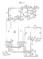
- FIG. 1 there is illustrated a schematic flow diagram of the process and apparatus of the present invention including adsorption vessels 10 and 12, and upper and lower gas diffusion vessels 14 and 16.
- the adsorption vessels 10 and 12 are filled with an appropriate adsorption material, such as the aforementioned carbon molecular sieves
- the upper and lower gas diffusion vessels 14 and 16 are provided with suitable gaseous diffusion barriers (GDB), as more fully hereinafter discussed.
- GDB gaseous diffusion barriers
- the process and apparatus of the present invention is pro vided with a feed compressor 18 including an inlet conduit 20 on the suction side thereof in fluid communication with a surge tank 24.
- the surge tank 24 is provided with a conduit 26 under the control of valve 28 connected to a conduit 30 under the control of valve 32 with the lower portion of the adsorption vessel 10 and to a conduit 34 under the control of valve 36 with the lower portion of the adsorption vessel 12.
- conduits 30 and 34 connected to the lower portion of the adsorption vessels 10 and 12 are connected by conduit 38 under the control of the valve 40 and conduit 42 under the control of valve 44, respectively to a conduit 46.
- the conduit 46 is connected by a conduit 48 under the control of valve 50 with a lower gas diffusion vessel 16 and by a conduit 52 under the control of valve 54 to a vent conduit 56.
- the lower gas diffusion vessel 16 on the permeate side is provided with a conduit 58 connected to the vent conduit 56 and on the non-permeate side is provided with a conduit 60.
- the conduit 60 is connected to a conduit 62 under the control of valve 64 and to a conduit 66 under the control of valve 67 to a holding tank 68.
- the holding tank 68 is provided with a conduit 70 connected to the suction side of a compressor 72 with the discharge side thereof being connected by a conduit 74 to a surge tank 76.
- the compressor 72 and related surge tank 76 are optionally provided to permit process flexibility.
- the holding tank 76 is provided with an outlet conduit 78 including a one-way valve 80 connected to a conduit 82.
- the conduit 82 is connected to the lower portion of adsorption vessel 10 by a conduit 84 under the control of valve 86 and to the lower portion of adsorption vessel 12 by a conduit 88 under the control of valve 90, as more fully hereinafter described.
- the adsorption vessels 10 and 12 are provided with upper conduits 92 and 94, respectively, under the control of valves 93 and 95 and including one-way check valves 96 and 98, respectively, connected to a conduit 100.
- the conduit 100 under the control of valve 102 is connected to a conduit 104 under the control of valve 106 with a product conduit 108 including one-way valve 110.
- the conduit 100 is connected by a conduit 112 under the control of valve 114 to the upper gas diffusion vessel 14.
- the upper gas diffusion vessel 14 is provided on the non-permeate side with a conduit 116 under the control of valve 118 connected to the product conduit 108, and is provided on the permeate side with a conduit 120 in fluid communication with the suction side of a compressor 122.
- the discharge side of the compressor 122 is connected by a conduit 124 to a holding tank 126 having a conduit 128 under the control of valve 121 and connected to conduits 130 and 132 under the control of valves 134 and 136 with upper conduits 92 and 94, respectively, of the adsorption vessels 10 and 12.
- a holding tank 126 having a conduit 128 under the control of valve 121 and connected to conduits 130 and 132 under the control of valves 134 and 136 with upper conduits 92 and 94, respectively, of the adsorption vessels 10 and 12.
- the compressor 122 and associated holding or surge tank 126 is optionally provided for process flexibility.
- the upper and lower gas diffusion vessels 14 and 16 are commercially available vessels, such as from UOP Fluid Systems (A Division of Allied-Signal), and provided with a suitable gaseous diffusion barrier which uses a silicone rubber membrane, or from Monsanto Chemical Company which uses a polysulfone membrane.
- the membrane used in the cells permits gaseous molecular oxygen to pass through the membranes faster than gaseous molecular nitrogen.
- the pressurized gas stream withdrawn from an adsorption column during regeneration following pressure equalization is introduced into the lower gaseous diffusion vessel 16 wherein there is formed a non-permeate gas stream relatively depleted in the adsorbate (or oxygen) and at an elevated pressure and a permeate gaseous stream of a higher level of the adsorbate which is vented.
- the non-permeate gas stream at an elevated pressure may be used to directly repressurize an adsorption bed, to repressurize an adsorption bed after recompression, to repressurize an adsorption bed following partial repressurization by equalization, or to be used as a feed gas stream, as more fully hereinafter discussed.
- a portion of the gas enriched product stream, as breakthrough is approached and product purity level falls off, is introduced into the upper gaseous diffusion vessel to form a non-permeate stream, i.e. a gaseous stream of a purity consistent with product design criteria, and a permeate stream to be used for purge and/or backfill, as more fully hereinafter discussed.
- a non-permeate stream i.e. a gaseous stream of a purity consistent with product design criteria
- a permeate stream to be used for purge and/or backfill
- adsorption vessel 10 For pressurization of adsorption vessel 10 and for production, air at ambient temperature in inlet conduit 20 is compressed in compressor 18 to a pressure of from 65 to 155 psig and passed by conduit 22 to the surge tank 24 and thence by conduits 26 and 30 to the lower portion of the adsorption vessel 10.
- the compressed air is introduced at a pressure of about 55 to 155 psig into adsorption vessel 10 wherein oxygen is selectively adsorbed therein to form a nitrogen-enriched gaseous stream withdrawn from adsorption vessel 10 by upper conduit 92 and passed at a pressure of from 60 to 150 psig by conduits 100, 104 and 108 to product storage or user equipment (not shown).
- the flow of compressed air to adsorption vessel 10 is continued until a point is reached where the level of oxygen in the nitrogen product gaseous stream reaches a predetermined threshold value unacceptable for product usage.
- a predetermined threshold value may be 1200 ppmv O2.
- the nitrogen-enriched gaseous stream (or "tail-end" product) in conduit 100 is purified in the upper gaseous diffusion vessel 14 by closing valve 106 to provide a non-permeate gas stream of acceptable purity withdrawn by conduit 116 and passed to product conduit 108.
- the permeate stream (the steam permeating the diffusion cell), slightly enriched in oxygen and at a lower pressure level, is passed by conduit 120 under the control of valves 121 and 136 at a pressure level of from 15 to 50 psig to the adsorption vessel 12 as a purge gas or as backfill for the adsorption bed undergoing regeneration.
- valves 28, 32, 44, 54, 93, 102, 114, 118, 121 and 136 are open.
- the compressor 122 and associated holding tank 126 are optionally provided as hereinabove discussed.
- the flow of gaseous product in conduit 100, having a level of impurity higher than threshold value, is continued to the upper gas diffusion vessel 14 for a period of until where further increase in the concentration of oxygen warrants shutdown of adsorption vessel 10 and the regeneration thereof.
- the adsorption vessel 12 has undergone pressure equalization or pressure balancing and is concomitantly prepared for the blowdown cycle.
- valves, 28, 32, 44, 50 and 67 are opened to allow pressurization of adsorption vessel 10 and to permit a flow of gas from the adsorption vessel 12 through the conduits 34, 42, 46 and 48 into the gaseous diffusion vessel 16 including a suitable gaseous diffusion barrier (GDB).
- GDB gaseous diffusion barrier
- oxygen readily passes through the gas-permeable membrane (GM).
- An oxygen-enriched gaseous stream (permeate) is withdrawn from the gas diffusion cell 16 by conduit 58 and passed via conduit 56 to vent.
- the non-permeate gaseous stream formed in the gaseous diffusion vessel 16 is available at a pressure of from at least about 15 to a pressure range of from 15 to 75 psig, as more fully hereinafter discussed.
- a predetermined concentration level of N2 e.g. 79% or alternatively determined by a pressure level of from 15 to 30 psig in the non-permeate stream, generally as determined by cycle time versus gas analysis
- the valve 50 in conduit 48 is closed and valve 54 in conduit 52 is opened to permit the gas stream in conduit 46 to be passed to vent via conduit 56.
- the permeate stream and non-permeate gaseous stream formed in the upper and lower gas diffusion cells 14 and 16 may be used in diverse ways to improve the process of gas enrichment utilizing pressure swing adsorption techniques.
- the non-permeate stream in conduit 60 may be used to repressurize via conduit 62 one or more regenerated beds (not shown) in a multi-bed PSA system which is generally effected concurrently with venting but before pressure equalization.
- the non-permeate stream may be passed to a holding tank 68 prior to introduction into such regenerated beds during repressurization.
- each non-permeate stream in conduit 66 may be compressed in compressor 72 and may be passed by conduit 82, in lieu of compressed air from holding tank 24 for the initial stage of product delivery.
- such non-permeate stream may be passed in lieu of compressed air for the initial stage of product delivery prior to admission of compressed air for the repressurization step.
- the adsorption vessel 12 will have undergone regeneration including blowdown and venting at which time the adsorption vessel 12 is readied for production and the adsorption vessel 10 is readied for regeneration.
- valves 32, 36, 134 and 136 are opened to effect pressure equalization between the adsorption vessels 10 and 12.
- the step of pressure equalization is effected for a time sufficient for such purpose, generally of from 2 to 20 seconds depending on the volume and type of the bed of adsorption material in the adsorption vessels 10 and 12.
- the step of pressure equalization for the PSA process of this invention is the same as in a normal PSA process; however, it is effected after processing the vent from the adsorption vessel undergoing regeneration with the lower gaseous diffusion cell and after processing tail-end product from the in production adsorption vessel with the upper gaseous diffusion cell.
- adsorption vessel 12 is placed in a nitrogen production mode and the adsorption vessel 10 into a regeneration mode.
- valves 28, 36, 40, 50, 67, 95, 102 and 106 are opened.
- compressed air in conduit 22 is now passed through conduits 26 and 34 to the adsorption vessel 12 to form a nitrogen-enriched product gaseous stream which is withdrawn from the adsorption vessel 12 through conduit 94 and passed by conduits 100, 104 and 108 to product storage.
- Regeneration of the bed of adsorbent material in adsorption vessel 10, i.e. blowdown and venting are effected in like manner to that of the bed of adsorp tion material in adsorption vessel 12.
- a gaseous stream is withdrawn from adsorption vessel 10 by conduit 38 and is passed through conduits 46 and 48 under the control of valve 50 to lower diffusion cell 16 as hereinabove described.
- valves 32, 36, 134 and 136 are opened to initiate and permit the step of pressure equalization.
- the gaseous stream withdrawn from an adsorption vessel in the conduit 46 at the inception of blowdown is at an elevated pressure of from 40 to 75 psig and is passed by conduit 48 under the control of valve 50 to the gaseous diffusion vessel 16, generally to a point where the pressure in the conduit 46 reaches about 15 psig.
- the gaseous stream is vented to atmosphere by closing valve 50 and opening valve 54 to permit gaseous flow through conduit 52.
- the PSA vent after pressure equalization between beds, is passed through the lower diffusion cell (polysulfone membrane).
- the nitrogen-enriched non-permeate stream from the lower diffusion cell is sent to the holding tank 68 and is then compressed to the feed pressure in compressor 72.
- the compressed gas in the holding tank 76 is introduced as feed to the adsorption vessels 10 or 12 during part of the production cycle.
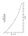
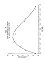
- FIGS. 3 to 5 illustrate vent flowrate, vent pressure, and vent oxygen concentration as a function of time for a nitrogen PSA employing BF (Bergbau-Forschung, West Germany) carbon molecular sieve and operating on 2 min. full cycle.
- the operating pressure is 120 psig and the profiles shown in FIG.S 3 to 5 are for the bed undergoing regeneration by venting.
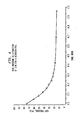
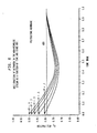
- the nitrogen concentration profiles for polysulfone membrane, as a function of stage cut (fraction of feed permeating the membrane), are shown in FIG. 6.
- the energy required to compress the fraction of non-permeate stream with a nitrogen concentration above 79% to feed pressure (120 psig) was calculated as a function of stage cut.
- FIG. 7 shows relative power requirements to produce a unit amount of product in the absence a diffusion cell, versus a diffusion cell containing polysulfone membrane. The optimum performance is obtained for a stage cut of about 50% and for this case about 8.5% energy savings are possible for polysulfone membranes and realized by use of a lower gaseous diffusion cell to provide a portion of the gaseous feed.
- the following example illustrates the cycling time for a PSA process using a non-permeate gas stream formed in the gaseous diffusion vessel 16 to pressurize an adsorption bed prior to pressure equalization (Valves - FIG. 1):
- the following example illustrates the cycling time for a nitrogen process in which a permeate stream from the gaseous diffusion vessel 14 is used to purge one of the adsorption beds (Valves - FIG. 1):
- the result is a reduction in energy requirements of from 5 to 15% per unit of product depending on the type of membrane material used in the diffusion cells.
- the present invention has been described in the context of PSA processing technology in the production of a nitrogen-enriched product stream; however, it will be understood by one of ordinary skill in that art that the present invention is applicable to gas enrichment technology, per se, using pressure swing adsorption techniques.
Landscapes
- Chemical & Material Sciences (AREA)
- Engineering & Computer Science (AREA)
- Analytical Chemistry (AREA)
- General Chemical & Material Sciences (AREA)
- Oil, Petroleum & Natural Gas (AREA)
- Chemical Kinetics & Catalysis (AREA)
- Separation Of Gases By Adsorption (AREA)
- Oxygen, Ozone, And Oxides In General (AREA)
- Separation Using Semi-Permeable Membranes (AREA)
Abstract
Description
- This invention relates to a process and apparatus for the selective enrichment of a compressed gaseous mixture in a chosen component, and more particularly to an improved pressure swing adsorption process and apparatus including gaseous diffusion barriers for gas enrichment.
- The use of adsorption techniques to separate a gaseous component from a gaseous stream initially was developed for the removal of carbon dioxide and water from air. The principles of gas adsorption were further refined to processes for gas enrichment of hydrogen, helium, argon, carbon monoxide, carbon dioxide, nitrous oxide, oxygen and nitrogen. Still further refinements using at least two adsorption vessels in a cycling pressurized relationship have resulted in an adsorption technique for gas enrichment commonly referred to as pressure swing adsorption (PSA).
- A conventional PSA process for enriching a gas, such as nitrogen from air, employs at least two adsorption beds filled with carbon molecular sieve material, each subjected to two or more, generally four distinct processing steps in each cycle. In a first step of the cycle, one adsorption bed is pressurized with concomitant nitrogen production while the other bed is regenerated, such as by venting. The adsorption bed may also be regenerated with countercurrent flow of product quality gas (referred to as "purge"). In a second step, sometimes referred to as pressure equalization, the adsorption beds are brought to an intermediate pressure by interconnection of the adsorption beds. In a third step of the cycle, the first adsorption bed is regenerated following the procedure used for the second bed while the second bed is put into production The last step of the cycle is pressure equalization between the beds. During such pressure swings, pressure conditions in the adsorption beds vary between about 15 psig to 120 psig in a process employing carbon molecular sieves for nitrogen production and somewhat lower pressure ranges in processes employing crystalline zeolites for producing oxygen.
- The use of an oxygen separation membrane in a pressure swing adsorption process is disclosed in Japanese patent Application Kokai No 58 - 151 304 (1983) wherein oxygen is produced by PSA techniques in adsorption columns filled with zeolites particles and wherein during the purge cycle of each adsorption column a oxygen purge gas is passed therethrough. The oxygen purge gas is obtained as a gaseous permeate stream from a gas separation membrane into which an enriched oxygen stream is introduced during a production cycle of each of the adsorption columns.
- US patent specification No 4 238 204 discloses a selective adsorption process for the recovery of a light gas, especially hydrogen, from a feed gas mixture by utilising a membrane permeator unit selectively permeable to said light gas to recover a more concentrated light gas from a stream comprising said light gas used to regenerate a selective adsorber unit, and recycling the concentrated light gas to the selective adsorber unit, either blended with the feed gas mixture or as purging gas for recovery of an added proportion of highly purified light gas product.
- Neither of these known processes is suitable for use when the product is a less readily adsorbed component of the gas mixture and diffuses through the membrane less readily than the other component(s). The invention, however, provides a process and apparatus which employ gas diffusion to improve an adsorption - desorption, e.g. PSA, method when the product component has these characteristics.
- According to the invention there is provided a process for the selective enrichment of a compressed gaseous mixture in a chosen component using at least two beds of adsorption material, wherein cycles are performed each comprising an adsorp tion step and a desorption step to produce from said gaseous mixture in said adsorption step a product gaseous stream enriched in said component and a gaseous stream withdrawn from an adsorption zone during said desorption step is introduced into a gas diffusion zone thereby forming a permeate stream, characterised in that the non-permeate stream is enriched in said component, and is returned to an adsorbent bed, and a gaseous stream enriched in said component is recovered from said gas diffusion zone.
- The invention also provides apparatus for the selective enrichment of a compressed gaseous mixture in a chosen component by pressure swing adsorption including at least two adsorption vessels containing beds of adsorption material; and a gaseous diffusion cell in fluid communication with said adsorption vessels to receive in use a gaseous stream withdrawn from a respective adsorption vessel during desorption of said bed of adsorption material, characterised in that the apparatus additionally includes means for returning a non-permeate gas stream enriched in said component to the vessels.
- The pressure levels of the product stream (and preferably also a vent stream) are preferably used to drive gaseous diffusion cells to produce a feed gas stream and preferably a purge gas stream to be used in the pressure swing adsorption process. On-line production time may thus be increased and waste pressure energy utilised thereby decreasing energy requirements per unit of production.
- The process and apparatus according to the present invention will now be described by way of example with reference to the accompanying drawings, in which:
- FIG. 1 is a schematic flow diagram of a preferred embodiment of the present invention;
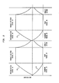
- FIG. 2 is a pressure profile of the adsorbent vessels for a complete cycle of a somewhat standard PSA process;
- FIG. 3 is a graph showing a typical vent flow rate as a function of time for nitrogen production according to one embodiment of the present invention;
- FIG. 4 is a graph showing a typical vent pressure as function of time for nitrogen production according to the embodiment of FIG. 3 of the present invention;
- FIG. 5 is a graph showing a typical oxygen concentration as a function of time for nitrogen production according to the embodiment of FIG. 3 of the present invention; and
- FIG. 6 is a graph showing a typical mole fraction of nitrogen in the non-permeate stream as a function of time and stage cut according to the embodiment of FIG. 3 of the present invention; and
- FIG. 7 is a graph showing power consumption per unit product as a function of stage cut according to the embodiment of FIG. 3 of the present invention.
- To facilitate an understanding of the present invention; certain valving, piping and instrumentation assemblies are not illustrated in the drawings. However, it will be understood that such additional valving, piping and instrumentation assemblies are provided consistent with accepted practices in the art. The present invention will be described in the context of nitrogen enrichment of air using an adsorbent bed of carbon molecular sieves, although it will be understood by one skilled in the art that the process and apparatus of the present invention are applicable to other gas enrichment processes using pressure swing adsorption.
- Referring now to FIG. 1, there is illustrated a schematic flow diagram of the process and apparatus of the present invention including
adsorption vessels gas diffusion vessels adsorption vessels gas diffusion vessels - The process and apparatus of the present invention is pro vided with a feed compressor 18 including an
inlet conduit 20 on the suction side thereof in fluid communication with asurge tank 24. Thesurge tank 24 is provided with aconduit 26 under the control ofvalve 28 connected to aconduit 30 under the control ofvalve 32 with the lower portion of theadsorption vessel 10 and to aconduit 34 under the control ofvalve 36 with the lower portion of theadsorption vessel 12. - The
conduits adsorption vessels conduit 38 under the control of thevalve 40 andconduit 42 under the control ofvalve 44, respectively to aconduit 46. Theconduit 46 is connected by aconduit 48 under the control ofvalve 50 with a lowergas diffusion vessel 16 and by aconduit 52 under the control ofvalve 54 to avent conduit 56. - The lower
gas diffusion vessel 16 on the permeate side is provided with aconduit 58 connected to thevent conduit 56 and on the non-permeate side is provided with aconduit 60. Theconduit 60 is connected to aconduit 62 under the control ofvalve 64 and to aconduit 66 under the control of valve 67 to aholding tank 68. Theholding tank 68 is provided with aconduit 70 connected to the suction side of acompressor 72 with the discharge side thereof being connected by aconduit 74 to asurge tank 76. Thecompressor 72 andrelated surge tank 76 are optionally provided to permit process flexibility. Theholding tank 76 is provided with anoutlet conduit 78 including a one-way valve 80 connected to aconduit 82. Theconduit 82 is connected to the lower portion ofadsorption vessel 10 by aconduit 84 under the control ofvalve 86 and to the lower portion ofadsorption vessel 12 by aconduit 88 under the control ofvalve 90, as more fully hereinafter described. - The
adsorption vessels upper conduits valves way check valves conduit 100. Theconduit 100 under the control ofvalve 102 is connected to aconduit 104 under the control ofvalve 106 with aproduct conduit 108 including one-way valve 110. Theconduit 100 is connected by aconduit 112 under the control ofvalve 114 to the uppergas diffusion vessel 14. The uppergas diffusion vessel 14 is provided on the non-permeate side with aconduit 116 under the control ofvalve 118 connected to theproduct conduit 108, and is provided on the permeate side with aconduit 120 in fluid communication with the suction side of acompressor 122. The discharge side of thecompressor 122 is connected by aconduit 124 to aholding tank 126 having aconduit 128 under the control ofvalve 121 and connected toconduits valves upper conduits adsorption vessels compressor 122 and associated holding orsurge tank 126 is optionally provided for process flexibility. - The upper and lower
gas diffusion vessels - In one aspect of the present invention, the pressurized gas stream withdrawn from an adsorption column during regeneration following pressure equalization is introduced into the lower
gaseous diffusion vessel 16 wherein there is formed a non-permeate gas stream relatively depleted in the adsorbate (or oxygen) and at an elevated pressure and a permeate gaseous stream of a higher level of the adsorbate which is vented. The non-permeate gas stream at an elevated pressure may be used to directly repressurize an adsorption bed, to repressurize an adsorption bed after recompression, to repressurize an adsorption bed following partial repressurization by equalization, or to be used as a feed gas stream, as more fully hereinafter discussed. - In another aspect of the present invention. a portion of the gas enriched product stream, as breakthrough is approached and product purity level falls off, is introduced into the upper gaseous diffusion vessel to form a non-permeate stream, i.e. a gaseous stream of a purity consistent with product design criteria, and a permeate stream to be used for purge and/or backfill, as more fully hereinafter discussed. The use of both the upper and lower gaseous diffusion assemblies may be efficaciously integrated into existing PSA plants.
- In operation, let it be assumed that the apparatus is in operation in a PSA process for producing high purity nitrogen, e.g. 99.9% nitrogen at a pressure of from 60 to 150 psig, wherein the
adsorption vessel 10 has been desorbed and is ready for production following pressurization, whereas theadsorption vessel 12 requires regeneration, and prior to that pressure equalization or balancing has been effected between theadsorption vessels valves - For pressurization of
adsorption vessel 10 and for production, air at ambient temperature ininlet conduit 20 is compressed in compressor 18 to a pressure of from 65 to 155 psig and passed byconduit 22 to thesurge tank 24 and thence byconduits adsorption vessel 10. The compressed air is introduced at a pressure of about 55 to 155 psig intoadsorption vessel 10 wherein oxygen is selectively adsorbed therein to form a nitrogen-enriched gaseous stream withdrawn fromadsorption vessel 10 byupper conduit 92 and passed at a pressure of from 60 to 150 psig byconduits - The flow of compressed air to
adsorption vessel 10 is continued until a point is reached where the level of oxygen in the nitrogen product gaseous stream reaches a predetermined threshold value unacceptable for product usage. For example, the average oxygen content of the nitrogen-enriched product stream may be 1000 ppmv O₂ whereupon a predetermined threshold value may be 1200 ppmv O₂. - At the point of reaching such a predetermined threshold value, the nitrogen-enriched gaseous stream (or "tail-end" product) in
conduit 100 is purified in the uppergaseous diffusion vessel 14 byclosing valve 106 to provide a non-permeate gas stream of acceptable purity withdrawn byconduit 116 and passed toproduct conduit 108. The permeate stream (the steam permeating the diffusion cell), slightly enriched in oxygen and at a lower pressure level, is passed byconduit 120 under the control ofvalves adsorption vessel 12 as a purge gas or as backfill for the adsorption bed undergoing regeneration. In this condition,valves compressor 122 and associatedholding tank 126 are optionally provided as hereinabove discussed. The flow of gaseous product inconduit 100, having a level of impurity higher than threshold value, is continued to the uppergas diffusion vessel 14 for a period of until where further increase in the concentration of oxygen warrants shutdown ofadsorption vessel 10 and the regeneration thereof. - At the initiation of pressurization of the
adsorption vessel 10 prior to production of an enriched gaseous stream theadsorption vessel 12 has undergone pressure equalization or pressure balancing and is concomitantly prepared for the blowdown cycle. During this condition, valves, 28, 32, 44, 50 and 67 are opened to allow pressurization ofadsorption vessel 10 and to permit a flow of gas from theadsorption vessel 12 through theconduits gaseous diffusion vessel 16 including a suitable gaseous diffusion barrier (GDB). In thegaseous diffusion vessel 16, oxygen readily passes through the gas-permeable membrane (GM). An oxygen-enriched gaseous stream (permeate) is withdrawn from thegas diffusion cell 16 byconduit 58 and passed viaconduit 56 to vent. The non-permeate gaseous stream formed in thegaseous diffusion vessel 16 is available at a pressure of from at least about 15 to a pressure range of from 15 to 75 psig, as more fully hereinafter discussed. Upon reaching a predetermined concentration level of N₂, e.g. 79% or alternatively determined by a pressure level of from 15 to 30 psig in the non-permeate stream, generally as determined by cycle time versus gas analysis, thevalve 50 inconduit 48 is closed andvalve 54 inconduit 52 is opened to permit the gas stream inconduit 46 to be passed to vent viaconduit 56. - As hereinabove discussed, the permeate stream and non-permeate gaseous stream formed in the upper and lower
gas diffusion cells gaseous diffusion cell 16, the non-permeate stream inconduit 60 may be used to repressurize viaconduit 62 one or more regenerated beds (not shown) in a multi-bed PSA system which is generally effected concurrently with venting but before pressure equalization. Depending on the cycling times of such regenerated beds, the non-permeate stream may be passed to aholding tank 68 prior to introduction into such regenerated beds during repressurization. Still further, in a multi-bed PSA system, i.e. two or more adsorption vessels, each non-permeate stream inconduit 66 may be compressed incompressor 72 and may be passed byconduit 82, in lieu of compressed air from holdingtank 24 for the initial stage of product delivery. In a multi-bed PSA system, i.e. two or more adsorption vessels, such non-permeate stream may be passed in lieu of compressed air for the initial stage of product delivery prior to admission of compressed air for the repressurization step. - As illustrated in FIG. 2 in a normal PSA operation, at the end of product delivery from
adsorption vessel 10, theadsorption vessel 12 will have undergone regeneration including blowdown and venting at which time theadsorption vessel 12 is readied for production and theadsorption vessel 10 is readied for regeneration. At such time,valves adsorption vessels - The step of pressure equalization is effected for a time sufficient for such purpose, generally of from 2 to 20 seconds depending on the volume and type of the bed of adsorption material in the
adsorption vessels - At a preselected time in the operational cycle,
adsorption vessel 12 is placed in a nitrogen production mode and theadsorption vessel 10 into a regeneration mode. In this condition,valves conduit 22 is now passed throughconduits adsorption vessel 12 to form a nitrogen-enriched product gaseous stream which is withdrawn from theadsorption vessel 12 throughconduit 94 and passed byconduits adsorption vessel 10, i.e. blowdown and venting are effected in like manner to that of the bed of adsorp tion material inadsorption vessel 12. During regeneration, a gaseous stream is withdrawn fromadsorption vessel 10 byconduit 38 and is passed throughconduits valve 50 tolower diffusion cell 16 as hereinabove described. - At the completion of regeneration of the bed of adsorption material in the
adsorption vessel 10 and the completion of product delivery from theadsorption vessel 12 including the purification of the tail-end product in the uppergaseous diffusion cell 14, thevalves - In accordance with one aspect of the present invention as hereinabove discussed, the gaseous stream withdrawn from an adsorption vessel in the
conduit 46 at the inception of blowdown is at an elevated pressure of from 40 to 75 psig and is passed byconduit 48 under the control ofvalve 50 to thegaseous diffusion vessel 16, generally to a point where the pressure in theconduit 46 reaches about 15 psig. Upon reaching such pressure, the gaseous stream is vented to atmosphere by closingvalve 50 andopening valve 54 to permit gaseous flow throughconduit 52. - The following examples are illustrative of the process of the present invention, and it is to be understood that the scope of the invention is not to be limited thereby.
- The PSA vent, after pressure equalization between beds, is passed through the lower diffusion cell (polysulfone membrane). Referring to FIG. 1, the nitrogen-enriched non-permeate stream from the lower diffusion cell is sent to the holding
tank 68 and is then compressed to the feed pressure incompressor 72. The compressed gas in theholding tank 76 is introduced as feed to theadsorption vessels - FIGS. 3 to 5 illustrate vent flowrate, vent pressure, and vent oxygen concentration as a function of time for a nitrogen PSA employing BF (Bergbau-Forschung, West Germany) carbon molecular sieve and operating on 2 min. full cycle. The operating pressure is 120 psig and the profiles shown in
FIG.S 3 to 5 are for the bed undergoing regeneration by venting. The nitrogen concentration profiles for polysulfone membrane, as a function of stage cut (fraction of feed permeating the membrane), are shown in FIG. 6. The energy required to compress the fraction of non-permeate stream with a nitrogen concentration above 79% to feed pressure (120 psig) was calculated as a function of stage cut. - Significant energy savings are realized since the non-permeate stream requires relatively smaller compression to be raised to feed pressure because of it being at a pressure higher than atmospheric, while fresh feed has to be compressed to operating pressure starting at atmospheric pressure. FIG. 7 shows relative power requirements to produce a unit amount of product in the absence a diffusion cell, versus a diffusion cell containing polysulfone membrane. The optimum performance is obtained for a stage cut of about 50% and for this case about 8.5% energy savings are possible for polysulfone membranes and realized by use of a lower gaseous diffusion cell to provide a portion of the gaseous feed.
- The following example illustrates the cycling time for a PSA process using a non-permeate gas stream formed in the
gaseous diffusion vessel 16 to pressurize an adsorption bed prior to pressure equalization (Valves - FIG. 1):
- The following example illustrates the cycling time for a nitrogen process in which a permeate stream from the
gaseous diffusion vessel 14 is used to purge one of the adsorption beds (Valves - FIG. 1):
- The following ex ample illustrates the cycling time for a PSA process using the combined processing steps as disclosed in Examples II and III (Valves - FIG. 1):

- By using the process of the present invention as directed to the use of gaseous diffusion vessels the result is a reduction in energy requirements of from 5 to 15% per unit of product depending on the type of membrane material used in the diffusion cells.
- The present invention has been described in the context of PSA processing technology in the production of a nitrogen-enriched product stream; however, it will be understood by one of ordinary skill in that art that the present invention is applicable to gas enrichment technology, per se, using pressure swing adsorption techniques.
- While the present invention has been described in connection with an exemplary embodiment thereof, it will be understood that many modifications will be apparent to those of ordinary skill in the art, and that this application is intended to cover any adaptations or variations thereof. Therefore, it is manifestly intended that this invention be only limited by the claims and the equivalents thereof.
Claims (10)
Applications Claiming Priority (2)
| Application Number | Priority Date | Filing Date | Title |
|---|---|---|---|
| US91409786A | 1986-10-01 | 1986-10-01 | |
| US914097 | 1986-10-01 |
Publications (3)
| Publication Number | Publication Date |
|---|---|
| EP0266884A2 true EP0266884A2 (en) | 1988-05-11 |
| EP0266884A3 EP0266884A3 (en) | 1988-05-25 |
| EP0266884B1 EP0266884B1 (en) | 1993-05-12 |
Family
ID=25433911
Family Applications (1)
| Application Number | Title | Priority Date | Filing Date |
|---|---|---|---|
| EP87308510A Expired - Lifetime EP0266884B1 (en) | 1986-10-01 | 1987-09-25 | Process and apparatus for pressure swing adsorption employing gaseous diffusion barriers |
Country Status (7)
| Country | Link |
|---|---|
| EP (1) | EP0266884B1 (en) |
| JP (1) | JPS6391119A (en) |
| AU (1) | AU575754B2 (en) |
| CA (1) | CA1305433C (en) |
| DE (1) | DE3785824T2 (en) |
| ES (1) | ES2040259T3 (en) |
| ZA (1) | ZA876419B (en) |
Cited By (12)
| Publication number | Priority date | Publication date | Assignee | Title |
|---|---|---|---|---|
| EP0312743A3 (en) * | 1987-10-22 | 1989-06-14 | Union Carbide Corporation | An integrated pressure swing adsorption/membrane separation |
| EP0290970A3 (en) * | 1987-05-09 | 1990-08-01 | Dragerwerk Aktiengesellschaft | Process for splitting and enriching a multicomponent gas with several separation chambers |
| EP0390392A3 (en) * | 1989-03-22 | 1991-01-02 | The BOC Group plc | Separation of gas mixtures |
| EP0411254A1 (en) * | 1989-05-12 | 1991-02-06 | Praxair Technology, Inc. | Production of dry, high purity nitrogen |
| EP0537614A1 (en) * | 1991-10-08 | 1993-04-21 | Praxair Technology, Inc. | Dual product pressure swing adsorption and membran operations |
| EP0537612A1 (en) * | 1991-10-08 | 1993-04-21 | Praxair Technology, Inc. | Dual product pressure swing adsorption process and system |
| WO1995003117A1 (en) * | 1993-07-21 | 1995-02-02 | Linde Aktiengesellschaft | Process and device for cleaning and decomposing a gas mixture |
| EP0668096A1 (en) * | 1993-12-23 | 1995-08-23 | Air Products And Chemicals, Inc. | Hydrogen recovery by adsorbent membranes |
| DE102017205598A1 (en) * | 2017-04-03 | 2018-10-04 | Inficon Gmbh | Process for recovering helium from a helium and oxygen-containing gas mixture |
| EP3781291B1 (en) * | 2018-04-16 | 2022-09-07 | Parker Hannifin EMEA S.à.r.l. | A pressure swing adsorption system |
| WO2023144540A1 (en) * | 2022-01-27 | 2023-08-03 | The University Of Sheffield | Pressure swing adsorption method and system for removal of co2 from air |
| IT202200027105A1 (en) * | 2022-12-29 | 2024-06-29 | Priver Ind Srl | System and method for the production of gaseous nitrogen |
Families Citing this family (10)
| Publication number | Priority date | Publication date | Assignee | Title |
|---|---|---|---|---|
| JP4538275B2 (en) * | 2004-08-05 | 2010-09-08 | 住友精化株式会社 | Method and system for parallel separation of oxygen gas and nitrogen gas |
| JP5982876B2 (en) * | 2012-02-29 | 2016-08-31 | 宇部興産株式会社 | Gas separation system |
| MY176621A (en) * | 2012-12-28 | 2020-08-18 | Osaka Gas Co Ltd | Gas purification apparatus |
| JP6091682B1 (en) * | 2016-03-31 | 2017-03-08 | 大阪瓦斯株式会社 | Pressure fluctuation adsorption gas production equipment |
| JP6091681B1 (en) * | 2016-03-31 | 2017-03-08 | 大阪瓦斯株式会社 | Pressure fluctuation adsorption gas production equipment |
| JP6091683B1 (en) * | 2016-03-31 | 2017-03-08 | 大阪瓦斯株式会社 | Pressure fluctuation adsorption gas production equipment |
| JP6837375B2 (en) * | 2017-04-07 | 2021-03-03 | 大陽日酸株式会社 | Hydrogen gas purification equipment and operation method of hydrogen gas purification equipment |
| RU173673U1 (en) * | 2017-05-16 | 2017-09-05 | Открытое акционерное общество "Аквасервис" | THREE-SADBORNE EJECTOR MEMBRANE-SORPTION INSTALLATION |
| CN110991938B (en) * | 2019-12-24 | 2023-12-22 | 上海申瑞继保电气有限公司 | Energy consumption calculation method for multi-product production line |
| JP7764489B2 (en) * | 2021-09-30 | 2025-11-05 | 日本碍子株式会社 | Gas separation system and gas separation method |
Family Cites Families (7)
| Publication number | Priority date | Publication date | Assignee | Title |
|---|---|---|---|---|
| US4238204A (en) * | 1979-06-18 | 1980-12-09 | Monsanto Company | Selective adsorption process |
| JPS58151304A (en) * | 1982-02-27 | 1983-09-08 | Nippon Sanso Kk | Production of oxygen by pressure swing method |
| US4440548A (en) * | 1982-04-19 | 1984-04-03 | Calgon Carbon Corporation | Pressure swing absorption system |
| US4398926A (en) * | 1982-04-23 | 1983-08-16 | Union Carbide Corporation | Enhanced hydrogen recovery from low purity gas streams |
| AU567567B2 (en) * | 1982-09-30 | 1987-11-26 | Union Carbide Corporation | Modified purge cycle in pressure swing adsorption process |
| US4512780A (en) * | 1983-11-08 | 1985-04-23 | Union Carbide Corporation | Pressure swing adsorption with intermediate product recovery |
| JPS61127609A (en) * | 1984-11-27 | 1986-06-14 | Kobe Steel Ltd | Purification device for helium |
-
1987
- 1987-08-27 ZA ZA876419A patent/ZA876419B/en unknown
- 1987-09-11 CA CA000546666A patent/CA1305433C/en not_active Expired - Lifetime
- 1987-09-25 ES ES198787308510T patent/ES2040259T3/en not_active Expired - Lifetime
- 1987-09-25 DE DE8787308510T patent/DE3785824T2/en not_active Expired - Fee Related
- 1987-09-25 EP EP87308510A patent/EP0266884B1/en not_active Expired - Lifetime
- 1987-09-30 AU AU79219/87A patent/AU575754B2/en not_active Ceased
- 1987-10-01 JP JP62249074A patent/JPS6391119A/en active Granted
Cited By (12)
| Publication number | Priority date | Publication date | Assignee | Title |
|---|---|---|---|---|
| EP0290970A3 (en) * | 1987-05-09 | 1990-08-01 | Dragerwerk Aktiengesellschaft | Process for splitting and enriching a multicomponent gas with several separation chambers |
| EP0312743A3 (en) * | 1987-10-22 | 1989-06-14 | Union Carbide Corporation | An integrated pressure swing adsorption/membrane separation |
| EP0390392A3 (en) * | 1989-03-22 | 1991-01-02 | The BOC Group plc | Separation of gas mixtures |
| EP0411254A1 (en) * | 1989-05-12 | 1991-02-06 | Praxair Technology, Inc. | Production of dry, high purity nitrogen |
| EP0537614A1 (en) * | 1991-10-08 | 1993-04-21 | Praxair Technology, Inc. | Dual product pressure swing adsorption and membran operations |
| EP0537612A1 (en) * | 1991-10-08 | 1993-04-21 | Praxair Technology, Inc. | Dual product pressure swing adsorption process and system |
| WO1995003117A1 (en) * | 1993-07-21 | 1995-02-02 | Linde Aktiengesellschaft | Process and device for cleaning and decomposing a gas mixture |
| EP0668096A1 (en) * | 1993-12-23 | 1995-08-23 | Air Products And Chemicals, Inc. | Hydrogen recovery by adsorbent membranes |
| DE102017205598A1 (en) * | 2017-04-03 | 2018-10-04 | Inficon Gmbh | Process for recovering helium from a helium and oxygen-containing gas mixture |
| EP3781291B1 (en) * | 2018-04-16 | 2022-09-07 | Parker Hannifin EMEA S.à.r.l. | A pressure swing adsorption system |
| WO2023144540A1 (en) * | 2022-01-27 | 2023-08-03 | The University Of Sheffield | Pressure swing adsorption method and system for removal of co2 from air |
| IT202200027105A1 (en) * | 2022-12-29 | 2024-06-29 | Priver Ind Srl | System and method for the production of gaseous nitrogen |
Also Published As
| Publication number | Publication date |
|---|---|
| JPS6391119A (en) | 1988-04-21 |
| JPH0567327B2 (en) | 1993-09-24 |
| CA1305433C (en) | 1992-07-21 |
| DE3785824D1 (en) | 1993-06-17 |
| DE3785824T2 (en) | 1993-08-19 |
| ZA876419B (en) | 1988-06-29 |
| AU575754B2 (en) | 1988-08-04 |
| ES2040259T3 (en) | 1993-10-16 |
| AU7921987A (en) | 1988-04-14 |
| EP0266884B1 (en) | 1993-05-12 |
| EP0266884A3 (en) | 1988-05-25 |
Similar Documents
| Publication | Publication Date | Title |
|---|---|---|
| US4765804A (en) | PSA process and apparatus employing gaseous diffusion barriers | |
| EP0266884A2 (en) | Process and apparatus for pressure swing adsorption employing gaseous diffusion barriers | |
| US5176722A (en) | Pressure swing adsorption method for separating gaseous mixtures | |
| US6425938B1 (en) | Single bed pressure swing adsorption process | |
| KR880000513B1 (en) | How to remove nitrogen gas from mixtures containing carbon monoxide gas and nitrogen gas | |
| US4440548A (en) | Pressure swing absorption system | |
| US5084075A (en) | Vacuum swing adsorption process for production of 95+% n2 from ambient air | |
| CA2237103C (en) | Pressure swing adsorption process with single adsorbent bed | |
| EP0383312B1 (en) | Adsorption process for recovering two high purity gas products from multicomponent gas mixtures | |
| US4914218A (en) | Adsorptive process for separating multicomponent gas mixtures | |
| CA1188231A (en) | Repressurization for pressure swing adsorption system | |
| CA2289909C (en) | Oxygen generation process and system using single adsorber vessel and single blower | |
| JP3050881B2 (en) | How to separate oxygen from air | |
| JPH06104176B2 (en) | Rapid adiabatic pressure swing adsorption method for multi-component gas separation and its equipment | |
| EP1101522A1 (en) | Pressure swing adsorption process | |
| US5997611A (en) | Single vessel gas adsorption system and process | |
| US6428607B1 (en) | Pressure swing adsorption process which provides product gas at decreasing bed pressure | |
| EP0055669B1 (en) | Repressurization for pressure swing adsorption system | |
| EP0055961B1 (en) | Repressurization process for pressure swing adsorption system | |
| EP0055962B1 (en) | Repressurisation for pressure swing adsorption system | |
| JPH0312307A (en) | Air separation method | |
| JPS60155520A (en) | Process for purifying carbon monoxide from mixed gas containing carbon monoxide gas by adsorption process | |
| JPS62241523A (en) | Separation and purification for carbon monoxide excellent in recovery efficiency |
Legal Events
| Date | Code | Title | Description |
|---|---|---|---|
| PUAI | Public reference made under article 153(3) epc to a published international application that has entered the european phase |
Free format text: ORIGINAL CODE: 0009012 |
|
| PUAL | Search report despatched |
Free format text: ORIGINAL CODE: 0009013 |
|
| AK | Designated contracting states |
Kind code of ref document: A2 Designated state(s): DE ES FR GB IT NL |
|
| AK | Designated contracting states |
Kind code of ref document: A3 Designated state(s): DE ES FR GB IT NL |
|
| 17P | Request for examination filed |
Effective date: 19881118 |
|
| 17Q | First examination report despatched |
Effective date: 19900809 |
|
| GRAA | (expected) grant |
Free format text: ORIGINAL CODE: 0009210 |
|
| ITF | It: translation for a ep patent filed | ||
| AK | Designated contracting states |
Kind code of ref document: B1 Designated state(s): DE ES FR GB IT NL |
|
| ET | Fr: translation filed | ||
| REF | Corresponds to: |
Ref document number: 3785824 Country of ref document: DE Date of ref document: 19930617 |
|
| REG | Reference to a national code |
Ref country code: ES Ref legal event code: FG2A Ref document number: 2040259 Country of ref document: ES Kind code of ref document: T3 |
|
| PGFP | Annual fee paid to national office [announced via postgrant information from national office to epo] |
Ref country code: FR Payment date: 19980820 Year of fee payment: 12 |
|
| PGFP | Annual fee paid to national office [announced via postgrant information from national office to epo] |
Ref country code: NL Payment date: 19980825 Year of fee payment: 12 |
|
| PGFP | Annual fee paid to national office [announced via postgrant information from national office to epo] |
Ref country code: GB Payment date: 19980826 Year of fee payment: 12 Ref country code: DE Payment date: 19980826 Year of fee payment: 12 |
|
| PGFP | Annual fee paid to national office [announced via postgrant information from national office to epo] |
Ref country code: ES Payment date: 19980916 Year of fee payment: 12 |
|
| PG25 | Lapsed in a contracting state [announced via postgrant information from national office to epo] |
Ref country code: GB Free format text: LAPSE BECAUSE OF NON-PAYMENT OF DUE FEES Effective date: 19990925 |
|
| PG25 | Lapsed in a contracting state [announced via postgrant information from national office to epo] |
Ref country code: ES Free format text: LAPSE BECAUSE OF NON-PAYMENT OF DUE FEES Effective date: 19990926 |
|
| PG25 | Lapsed in a contracting state [announced via postgrant information from national office to epo] |
Ref country code: NL Free format text: LAPSE BECAUSE OF NON-PAYMENT OF DUE FEES Effective date: 20000401 |
|
| GBPC | Gb: european patent ceased through non-payment of renewal fee |
Effective date: 19990925 |
|
| PG25 | Lapsed in a contracting state [announced via postgrant information from national office to epo] |
Ref country code: FR Free format text: LAPSE BECAUSE OF NON-PAYMENT OF DUE FEES Effective date: 20000531 |
|
| NLV4 | Nl: lapsed or anulled due to non-payment of the annual fee |
Effective date: 20000401 |
|
| PG25 | Lapsed in a contracting state [announced via postgrant information from national office to epo] |
Ref country code: DE Free format text: LAPSE BECAUSE OF NON-PAYMENT OF DUE FEES Effective date: 20000701 |
|
| REG | Reference to a national code |
Ref country code: FR Ref legal event code: ST |
|
| REG | Reference to a national code |
Ref country code: ES Ref legal event code: FD2A Effective date: 20001013 |
|
| PG25 | Lapsed in a contracting state [announced via postgrant information from national office to epo] |
Ref country code: IT Free format text: LAPSE BECAUSE OF NON-PAYMENT OF DUE FEES;WARNING: LAPSES OF ITALIAN PATENTS WITH EFFECTIVE DATE BEFORE 2007 MAY HAVE OCCURRED AT ANY TIME BEFORE 2007. THE CORRECT EFFECTIVE DATE MAY BE DIFFERENT FROM THE ONE RECORDED. Effective date: 20050925 |
|
| PLBE | No opposition filed within time limit |
Free format text: ORIGINAL CODE: 0009261 |
|
| STAA | Information on the status of an ep patent application or granted ep patent |
Free format text: STATUS: NO OPPOSITION FILED WITHIN TIME LIMIT |