EP0266806A2 - Hydraulikmotor mit radial angeordneten, rohrförmigen Antriebselementen - Google Patents
Hydraulikmotor mit radial angeordneten, rohrförmigen Antriebselementen Download PDFInfo
- Publication number
- EP0266806A2 EP0266806A2 EP87201436A EP87201436A EP0266806A2 EP 0266806 A2 EP0266806 A2 EP 0266806A2 EP 87201436 A EP87201436 A EP 87201436A EP 87201436 A EP87201436 A EP 87201436A EP 0266806 A2 EP0266806 A2 EP 0266806A2
- Authority
- EP
- European Patent Office
- Prior art keywords
- radial
- propulsors
- spherical
- propulsor
- tubular
- Prior art date
- Legal status (The legal status is an assumption and is not a legal conclusion. Google has not performed a legal analysis and makes no representation as to the accuracy of the status listed.)
- Granted
Links
- 239000012530 fluid Substances 0.000 claims abstract description 34
- 238000007599 discharging Methods 0.000 claims abstract description 3
- 229920000642 polymer Polymers 0.000 claims description 11
- 238000007789 sealing Methods 0.000 claims description 10
- 230000002093 peripheral effect Effects 0.000 claims description 4
- 230000008878 coupling Effects 0.000 claims description 2
- 238000010168 coupling process Methods 0.000 claims description 2
- 238000005859 coupling reaction Methods 0.000 claims description 2
- 238000003780 insertion Methods 0.000 claims description 2
- 230000037431 insertion Effects 0.000 claims description 2
- 238000010276 construction Methods 0.000 description 3
- 238000005461 lubrication Methods 0.000 description 3
- 239000002184 metal Substances 0.000 description 3
- 230000001050 lubricating effect Effects 0.000 description 2
- 235000019892 Stellar Nutrition 0.000 description 1
- 230000015572 biosynthetic process Effects 0.000 description 1
- 238000000576 coating method Methods 0.000 description 1
- 230000008021 deposition Effects 0.000 description 1
- 238000007667 floating Methods 0.000 description 1
- 230000008595 infiltration Effects 0.000 description 1
- 238000001764 infiltration Methods 0.000 description 1
- 230000001788 irregular Effects 0.000 description 1
- 238000003754 machining Methods 0.000 description 1
- 238000012423 maintenance Methods 0.000 description 1
- 230000010355 oscillation Effects 0.000 description 1
- 230000002028 premature Effects 0.000 description 1
Images

Classifications
-
- F—MECHANICAL ENGINEERING; LIGHTING; HEATING; WEAPONS; BLASTING
- F03—MACHINES OR ENGINES FOR LIQUIDS; WIND, SPRING, OR WEIGHT MOTORS; PRODUCING MECHANICAL POWER OR A REACTIVE PROPULSIVE THRUST, NOT OTHERWISE PROVIDED FOR
- F03C—POSITIVE-DISPLACEMENT ENGINES DRIVEN BY LIQUIDS
- F03C1/00—Reciprocating-piston liquid engines
- F03C1/02—Reciprocating-piston liquid engines with multiple-cylinders, characterised by the number or arrangement of cylinders
- F03C1/04—Reciprocating-piston liquid engines with multiple-cylinders, characterised by the number or arrangement of cylinders with cylinders in star or fan arrangement
- F03C1/053—Reciprocating-piston liquid engines with multiple-cylinders, characterised by the number or arrangement of cylinders with cylinders in star or fan arrangement the pistons co-operating with an actuated element at the inner ends of the cylinders
-
- F—MECHANICAL ENGINEERING; LIGHTING; HEATING; WEAPONS; BLASTING
- F16—ENGINEERING ELEMENTS AND UNITS; GENERAL MEASURES FOR PRODUCING AND MAINTAINING EFFECTIVE FUNCTIONING OF MACHINES OR INSTALLATIONS; THERMAL INSULATION IN GENERAL
- F16J—PISTONS; CYLINDERS; SEALINGS
- F16J15/00—Sealings
- F16J15/16—Sealings between relatively-moving surfaces
- F16J15/164—Sealings between relatively-moving surfaces the sealing action depending on movements; pressure difference, temperature or presence of leaking fluid
-
- F—MECHANICAL ENGINEERING; LIGHTING; HEATING; WEAPONS; BLASTING
- F16—ENGINEERING ELEMENTS AND UNITS; GENERAL MEASURES FOR PRODUCING AND MAINTAINING EFFECTIVE FUNCTIONING OF MACHINES OR INSTALLATIONS; THERMAL INSULATION IN GENERAL
- F16J—PISTONS; CYLINDERS; SEALINGS
- F16J15/00—Sealings
- F16J15/56—Other sealings for reciprocating rods
Definitions
- the Invention relates to a hydraulic motor comprising radial propulsors and tubular elements offering unimpeded flow, so that a hydraulic driving fluid can flow in and out freely from the sealing surfaces during each cycle.
- hydraulic motors comprising radial propulsory means and substantially made up of a number of radial actuating means or propulsors acting on the eccentric portion of a shaft and thus driving it in rotation when cyclically supplied with pressure fluid via a rotary distributor- actuated by the drive shaft.
- the problem therefore is to provide an improved motor comprising radial propulsors in which the pressure of the hydraulic fluid acts directly on the eccentric shaft component while ensuring vigorous lubrication and dissipation of heat together with adequate guidance of the aligment between the propulsor components even when in the most extended position, while simultaneously ensuring minimum bulk in the radial direction and optimum distribution of forces in the external casing.
- the invention provides a hydraulic motor having radial propulsors and comprising an outer casing in which a shaft is mounted,and has an eccentric spherical portion around which a number of substantially radial propulsors are disposed, each propulsor comprising a first tubular member bearing in sealing-tight manner against a cap having a spherical surface and disposed in the outer casing, the first tubular member being telescopically coupled, with interposition of sealing means, to a second tubular member bearing in sealing-tight manner against the eccentric spherical portion of the shaft, an Inserted resilient means being adapted to urge the tubular members against the corresponding spherical contact surfaces, the caps and the outer casing being formed with ducts for supplying and discharging hydraulic fluid to and from the interior of the propulsors and connected to a rotary distributor actuated by the shaft shaft, the outer casing being made up of two substantially symmetrical separate shells connected together, means being present
- the first tubular member which bears against one of the spherical-surface caps in the external casing, is inserted inside the second tubular member, bearing against the eccentric spherical portion of the shaft.
- the means for mechanically connecting the internal tubular propulsor members to the spherical cap surfaces are internally anchored to the tubular members, and conveniently comprise a tie rod connected to a disc coupled to the internal tubular member, the rod having a flared head bearing against a ring borne by the cap to which the internal tubular element is connected, the tubular element being free to oscillate on the cap surface, the length of the rod being such as to allow reduced clearance between the cap surface and the surface of the tubular element in contact therewith, sufficient to prevent wear during sliding.
- the means for mechanically connecting the outer tubular propulsor members to the surface of a spherical driving-shaft portion comprise a pair of rings coaxial with the spherical portion and having a raised peripheral part for insertion in peripheral grooves on the outside of the outer tubular members near the surface in contact with the spherical portion of the shaft; optionally the rings are centred around cylindrical shaft portions coaxial with the spherical portion thereof, and secured thereto in the axial direction by resilient rings, or optionally the rings are free in the radial direction and locked in the axial direction in the respective positions by corresponding surfaces of the outer casing.
- the sealing means interposed between the tubular propulsor members comprise a polymer ring having a cylindrical internal surface and a front surface which is flat towards the exterior of the propulsor, the ring being inserted with radial and axial clearance into a corresponding cavity in the external tubular member, leaving an axial and radial clear space in the cavity so as to allow hydraulic fluid at the operating pressure to flow from the interior of the propulsor into the cavity in contact with the polymer ring and thrust it in the axial direction so as to clamp its flat front surface against the edge of the cavity facing the end of the tubular member, and tightly seal it, the hydraulic fluid also transmitting a thrust in the radial direction clamping the polymer ring against the external wall of the Internal tubular element and sealing it, the pressure of the hydraulic fluid keeping the polymer ring radially centred in its seat and keeping the internal tubular member centred relative to the external tubular member in the region in question.
- the front surface of the polymer ring facing the interior of the propulsor has one or more radial notches so that when the ring is pressed against the edge of the cavity towards the interior of the propulsor and there is a negative pressure inside the propulsor, the notches form passages for hydraulic fluid to flow from the interior of the casing into the interior of the propulsor and compensate the negative pressure and prevent cavitation.
- the outer casing is made up of two interconnected shells separated at a plane at right angles to the axis of the drive shaft and symmetrical relative to the bearings of the drive shaft, the plane also containing the axes of the propulsors.
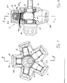
- the motor according to the invention comprises an external casing (general reference 1) inside which an eccentric shaft 3 is rotatably mounted on bearings 2 and has a spherical portion 4 integral therewith and eccentrically disposed relative to the axis of rotation of the motor.
- a number ' of propulsory means 5 are disposed in substantially radial manner around the spherical portion 4 and bear at one end against portion 4 and at the other end against respective spherical caps 6 permanently housed in the external casing 1 and formed with ducts 7 for supplying hydraulic fluid to the propulsory means and terminating at a rotary distributor 8.
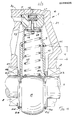
- each propulsory means comprises an internal tubular member 9 bearing at one end against an associated cap 6 on which the external tubular member 10 is telescopically mounted and its end bears against the spherical portion 4 of shaft 3.
- Sealing-tightness between members 9 and 10 is provided by a gasket 11, and a spring 12 inserted between members 9 and 10 is adapted to hold members 9 and 10 against cap 6 and portion 4 respectively.
- the internal tubular member 9 is also mechanically connected to cap 6, against which it bears via a perforated disc 13 formed with wide holes 14 for hydraulic fluid to flow as required to and from the interior of the propulsory means, which is connected to a rod 15 having a head 16 bearing on a ring 17 inserted in an aperture 18 in cap 6 and blocked by a plug 19.
- Ring 23 is illustrated in Fig. 3 in two alternative embodiments, on the right and the left of the drawing respectively.
- the embodiment illustrated on the right of Fig. 3 comprises a floating ring bearing at the rear against the facing surface 24 of member 1, whereas the embodiment illustrated at the left of the drawing is a ring 23 centred around the eccentric . portion 25 of shaft 3, which is adjacent and coaxial with the spherical portion 4, on which the ring is locked in the axial direction by a resilient ring 26 or the like.
- the means for mechanically connecting members 9, 10 to the corresponding spherical contact surfaces 6 and 4, i.e. disc 13, rod 15 and rings 23, are adapted in either embodiment or in similar embodiments to prevent the tubular members becoming detached from the associated spherical contact surfaces under particular conditions in spite of the action of spring 12, if cavitation occurs in the propulsory means, e.g. if the motor is driven in rotation by the components connected to it. Such detachment of the tubular members would result in knocking or pounding, which would cause damage to the surfaces and loss of hydraulic sealing-tightness.
- the retaining means allow a small clearance between the tubular members and the corresponding spherical contact surfaces so as to prevent wear during motion but so as to limit any detachment of the tubular members from the corresponding contact surfaces to a very small value and thus avoid damage even in such circumstances.
- the internal tubular member is placed in contact with cap 6 whereas the external tubular member 10 bears against the spherical portion 4.
- the object is to prevent misalignment or jamming between members 9 and 10.
- the means for mechanically connecting the internal tubular member 9 can be disposed inside it and leave its external surface unimpeded up to the end in,contact with the cap 6 so that the external member 10 can run over it in the minimum extended position illustrated in Fig. 3, whereas the rings 23, which must be disposed outside the associated tubular member, can be received in respective seats 21 on the tubular members without thereby restricting the maximum possible travel of the cylinders.
- portion 4 and also of caps 6 can be without metal surface coatings or the like and thus prevented from jamming, even in the absence of seals on the coupling surfaces of members 9 and 10.
- tubular propulsor components are hydrostatically balanced so that the areas of each member acted upon axially by the fluid pressure are such that in every case the tubular members are urged against the associated spherical surfaces, thus guaranteeing sealing-tightness under all conditions, in co-operation with the spring 12.
- the end surfaces of the tubular members are made up of narrow circular rings so as to limit the area subjected to the thrust of the infiltrating fluid.
- the described structure greatly prolongs the life of the motor without requiring maintenance or reducing the capacity.
- the seal 11 disposed between member 9 and member 10 is adapted to maintain hydraulic sealing-tightness between them, with a low coefficient of wear and reduced bulk in the radial direction. It also constitutes the front surface on which member 10 moves on member 9. As Fig. 5 shows, the seal 11 comprises a polymer ring 27 inserted into a corresponding cavity 28 formed in member 10 with axial and radial clearance.
- the pressure of the hydraulic fluid operates in the axial. direction, moving ring 27 to the end of cavity 28, and also in the radial direction, clamping the ring around member 9.
- ring 27 of seal 11 advantageously has a portion 27a wide enough to ensure an axial seal against the front edge 28a of its seat, and a thinner portion 27b giving the ring ' the flexibility required for easy fitting into its seat.
- the surface of ring 27 facing the interior of the propulsor may advantageously be formed with one or more radial notches 29.
- a negative pressure occurs inside the propulsor, e.g. if the motor is driven in rotation by components connected to it, the pressure of the hydraulic fluid inside casing 1, represented by arrows P in the drawing, urges the ring from the side opposite its seat and presses it against the wall of the cavity facing the interior of the propulsor.
- cavities 29 allow fluid to flow from the casing to the interior of the propulsor, thus balancing the pressure inside and preventing a vacuum or associated cavitation, which cause irregular operation and premature wear of the motor.
- Ring 27 in short acts as a one-wsy valve ensuring sealing-tightness at the pressure inside the propulsor under normal operating conditions, though permitting hydraulic fluid to enter if the pressure drops.
- the external casing 1 of the motor according to the invention is made up of two symmetrical stellar shells 30 and 31, each housing one of the bearings 2 and forming half of the seat receiving the caps 6.
- Shells 30, 31 are coupled by screws 32 with interposition of a gasket for sealing the hydraulic lubricating fluid inside the frame.
- the frame is constructed so that stresses due to the action of the propulsors are symmetrical in the two shells, resulting in equal deformation thereof in the absence of relative motion between them. Consequently, screws 32 are not subjected to forces during operation of the motor, since they do not have to counteract differences in the deformation of the parts in contact or withstand the thrust of the propulsors, and the seal is not damaged by possible relative motion between the parts in contact when different constructions are adopted.
- the two shells are also particularly advantageous both because they reduce the bulk and can improve the distribution of forces in the structure and thus reduce the thickness of the frame, and also because the required machining is less extensive and simpler and it is easier to install the propulsors and other ccmponents in the motor and thus save substantial costs.
Landscapes
- Engineering & Computer Science (AREA)
- General Engineering & Computer Science (AREA)
- Mechanical Engineering (AREA)
- Chemical & Material Sciences (AREA)
- Combustion & Propulsion (AREA)
- Hydraulic Motors (AREA)
Priority Applications (1)
| Application Number | Priority Date | Filing Date | Title |
|---|---|---|---|
| AT87201436T ATE70339T1 (de) | 1986-08-11 | 1987-07-27 | Hydraulikmotor mit radial angeordneten, rohrfoermigen antriebselementen. |
Applications Claiming Priority (2)
| Application Number | Priority Date | Filing Date | Title |
|---|---|---|---|
| IT8621466A IT1213481B (it) | 1986-08-11 | 1986-08-11 | Motore idraulico a propulsori radiali ad elementi tubolari a passaggio completo. |
| IT2146686 | 1986-08-11 |
Publications (3)
| Publication Number | Publication Date |
|---|---|
| EP0266806A2 true EP0266806A2 (de) | 1988-05-11 |
| EP0266806A3 EP0266806A3 (en) | 1988-08-17 |
| EP0266806B1 EP0266806B1 (de) | 1991-12-11 |
Family
ID=11182228
Family Applications (1)
| Application Number | Title | Priority Date | Filing Date |
|---|---|---|---|
| EP87201436A Expired EP0266806B1 (de) | 1986-08-11 | 1987-07-27 | Hydraulikmotor mit radial angeordneten, rohrförmigen Antriebselementen |
Country Status (5)
| Country | Link |
|---|---|
| EP (1) | EP0266806B1 (de) |
| AT (1) | ATE70339T1 (de) |
| DE (1) | DE3775171D1 (de) |
| ES (1) | ES2027280T3 (de) |
| IT (1) | IT1213481B (de) |
Cited By (2)
| Publication number | Priority date | Publication date | Assignee | Title |
|---|---|---|---|---|
| EP1609987A1 (de) * | 2004-06-16 | 2005-12-28 | PARKER CALZONI S.r.l. | Hydraulikmotor |
| EP3023637A1 (de) * | 2014-11-07 | 2016-05-25 | Parker Hannifin Manufacturing S.r.l. | Fluid-säulen-hydraulikmotor mit vereinfachten mitteln zum halten der antriebselemente gegen zugehörige gleitflächen |
Citations (11)
| Publication number | Priority date | Publication date | Assignee | Title |
|---|---|---|---|---|
| FR1193072A (fr) * | 1958-03-05 | 1959-10-30 | Semt | Segment de piston perfectionné |
| US3396976A (en) * | 1965-07-13 | 1968-08-13 | Philips Corp | Device, particularly hot-gas reciprocating engine |
| DE2015890A1 (de) * | 1967-09-29 | 1970-10-15 | Riva Calzoni Spa | Hydraulischer Motor mit radialen Antriebsorganen |
| US3577830A (en) * | 1967-09-29 | 1971-05-04 | Riva Calzoni Spa | Hydraulic motor |
| FR2089102A5 (de) * | 1970-04-03 | 1972-01-07 | Lucas Industries Ltd | |
| US3742819A (en) * | 1970-02-20 | 1973-07-03 | New Inuent Sa | Telescopic piston-cylinder assembly for hydraulic machines and machine components |
| GB1357995A (en) * | 1971-04-17 | 1974-06-26 | Bosch Gmbh Robert | Piston and slide-shoe assembly for hydraulic piston machines |
| US3834719A (en) * | 1970-10-27 | 1974-09-10 | Nippon Piston Ring Co Ltd | Piston head assembly having an l-shaped piston ring |
| DE1503313B2 (de) * | 1963-06-25 | 1974-12-12 | Chamberlain Industries Ltd., London | Einrichtung zur Steuerung eines mehrzylindrigen Hydraulikmotors |
| SU714042A1 (ru) * | 1977-01-17 | 1980-02-05 | Одесский Завод "Стройгидравлика" | Радиально-поршневой эксцентриковый гидромотор |
| SU1000582A1 (ru) * | 1981-10-12 | 1983-02-28 | Ордена Трудового Красного Знамени Одесский Завод "Стройгидравлика" | Радиально-поршневой эксцентриковый гидромотор |
-
1986
- 1986-08-11 IT IT8621466A patent/IT1213481B/it active
-
1987
- 1987-07-27 AT AT87201436T patent/ATE70339T1/de not_active IP Right Cessation
- 1987-07-27 EP EP87201436A patent/EP0266806B1/de not_active Expired
- 1987-07-27 DE DE8787201436T patent/DE3775171D1/de not_active Expired - Lifetime
- 1987-07-27 ES ES198787201436T patent/ES2027280T3/es not_active Expired - Lifetime
Patent Citations (11)
| Publication number | Priority date | Publication date | Assignee | Title |
|---|---|---|---|---|
| FR1193072A (fr) * | 1958-03-05 | 1959-10-30 | Semt | Segment de piston perfectionné |
| DE1503313B2 (de) * | 1963-06-25 | 1974-12-12 | Chamberlain Industries Ltd., London | Einrichtung zur Steuerung eines mehrzylindrigen Hydraulikmotors |
| US3396976A (en) * | 1965-07-13 | 1968-08-13 | Philips Corp | Device, particularly hot-gas reciprocating engine |
| DE2015890A1 (de) * | 1967-09-29 | 1970-10-15 | Riva Calzoni Spa | Hydraulischer Motor mit radialen Antriebsorganen |
| US3577830A (en) * | 1967-09-29 | 1971-05-04 | Riva Calzoni Spa | Hydraulic motor |
| US3742819A (en) * | 1970-02-20 | 1973-07-03 | New Inuent Sa | Telescopic piston-cylinder assembly for hydraulic machines and machine components |
| FR2089102A5 (de) * | 1970-04-03 | 1972-01-07 | Lucas Industries Ltd | |
| US3834719A (en) * | 1970-10-27 | 1974-09-10 | Nippon Piston Ring Co Ltd | Piston head assembly having an l-shaped piston ring |
| GB1357995A (en) * | 1971-04-17 | 1974-06-26 | Bosch Gmbh Robert | Piston and slide-shoe assembly for hydraulic piston machines |
| SU714042A1 (ru) * | 1977-01-17 | 1980-02-05 | Одесский Завод "Стройгидравлика" | Радиально-поршневой эксцентриковый гидромотор |
| SU1000582A1 (ru) * | 1981-10-12 | 1983-02-28 | Ордена Трудового Красного Знамени Одесский Завод "Стройгидравлика" | Радиально-поршневой эксцентриковый гидромотор |
Non-Patent Citations (2)
| Title |
|---|
| Soviet Inventions Illustrated, Section Mechanical, Week 84/01, Abstract No. 0048 13, Q55, Derwent Publications Ltd., London, GB; & SU,A,1000582 (ODESS STROIGIDRAVLI) 05-03-1983. * |
| Soviet Inventions Illustrated, Section Mechanical, Week C 38, 29th October 1980, Abstract No. J2257, Q 55, Derwent Publications Ltd., London, GB; & SU,A,714042 (ODESS STROIGIDRAVLI) 05-02-1980. * |
Cited By (3)
| Publication number | Priority date | Publication date | Assignee | Title |
|---|---|---|---|---|
| EP1609987A1 (de) * | 2004-06-16 | 2005-12-28 | PARKER CALZONI S.r.l. | Hydraulikmotor |
| US7267042B2 (en) | 2004-06-16 | 2007-09-11 | Parker Calzoni S.R.L. | Hydraulic motor with telescopic propulsion members retained sealingly against associated contact surfaces by internal resilient means |
| EP3023637A1 (de) * | 2014-11-07 | 2016-05-25 | Parker Hannifin Manufacturing S.r.l. | Fluid-säulen-hydraulikmotor mit vereinfachten mitteln zum halten der antriebselemente gegen zugehörige gleitflächen |
Also Published As
| Publication number | Publication date |
|---|---|
| EP0266806A3 (en) | 1988-08-17 |
| DE3775171D1 (de) | 1992-01-23 |
| ES2027280T3 (es) | 1992-06-01 |
| IT1213481B (it) | 1989-12-20 |
| IT8621466A0 (it) | 1986-08-11 |
| ATE70339T1 (de) | 1991-12-15 |
| EP0266806B1 (de) | 1991-12-11 |
Similar Documents
| Publication | Publication Date | Title |
|---|---|---|
| US5697765A (en) | Hydraulic motor | |
| WO1999009340A1 (en) | Method and apparatus for optimizing barrier fluid flow for promoting cool running of a cartridge dual seal | |
| US4877383A (en) | Device having a sealed control opening and an orbiting valve | |
| AU7370696A (en) | Bearing housing seal | |
| US6181034B1 (en) | Radial oscillating motor | |
| EP0420995A1 (de) | Hydraulischer motor mit reduktionsgetriebe | |
| EP1882081B1 (de) | Ausgleichsplatten-shuttleventil | |
| EP0266806A2 (de) | Hydraulikmotor mit radial angeordneten, rohrförmigen Antriebselementen | |
| GB2195150A (en) | Axial air motor | |
| EP0778418B1 (de) | Drehkolbenpumpe | |
| CN210919813U (zh) | 盾构机主驱动组件用关节轴承及盾构机 | |
| EP3783240B1 (de) | Lageranordnung und verdichter damit | |
| US20240044319A1 (en) | Hydrostatic radial piston unit | |
| EP0814264B1 (de) | Rotierende Maschine mit Kolbenschieberventil | |
| US4445825A (en) | Radial piston machine | |
| US5989001A (en) | Planetary rotation machine with hydrostatically mounted control part, and control part for this purpose | |
| MXPA96004173A (en) | Pump with improved support arrangement for ax position control | |
| EP3784932B1 (de) | Dichtungsanordnung, hydrodynamische maschine und fahrzeug | |
| EP4222370B1 (de) | Bremsmechanismus für eine radialkolbeneinheit | |
| CA1275859C (en) | Closed center hydraulic devide | |
| US6945759B2 (en) | Engine driven dry air pump with a flange mounted oil drain | |
| US20240309839A1 (en) | Bearing arrangement for radial piston units | |
| RU225644U1 (ru) | Ротатор с шиберным двигателем | |
| CA1156202A (en) | Rotary piston machine | |
| KR100603675B1 (ko) | 유압식 회전형 축방향 피스톤 엔진 |
Legal Events
| Date | Code | Title | Description |
|---|---|---|---|
| PUAI | Public reference made under article 153(3) epc to a published international application that has entered the european phase |
Free format text: ORIGINAL CODE: 0009012 |
|
| 17P | Request for examination filed |
Effective date: 19870814 |
|
| AK | Designated contracting states |
Kind code of ref document: A2 Designated state(s): AT BE CH DE ES FR GB IT LI NL |
|
| PUAL | Search report despatched |
Free format text: ORIGINAL CODE: 0009013 |
|
| AK | Designated contracting states |
Kind code of ref document: A3 Designated state(s): AT BE CH DE ES FR GB IT LI NL |
|
| 17Q | First examination report despatched |
Effective date: 19900221 |
|
| RAP3 | Party data changed (applicant data changed or rights of an application transferred) |
Owner name: RIVA CALZONI S.P.A. |
|
| GRAA | (expected) grant |
Free format text: ORIGINAL CODE: 0009210 |
|
| AK | Designated contracting states |
Kind code of ref document: B1 Designated state(s): AT BE CH DE ES FR GB IT LI NL |
|
| PG25 | Lapsed in a contracting state [announced via postgrant information from national office to epo] |
Ref country code: LI Effective date: 19911211 Ref country code: CH Effective date: 19911211 Ref country code: BE Effective date: 19911211 |
|
| REF | Corresponds to: |
Ref document number: 70339 Country of ref document: AT Date of ref document: 19911215 Kind code of ref document: T |
|
| REF | Corresponds to: |
Ref document number: 3775171 Country of ref document: DE Date of ref document: 19920123 |
|
| ET | Fr: translation filed | ||
| ITF | It: translation for a ep patent filed | ||
| REG | Reference to a national code |
Ref country code: CH Ref legal event code: PL |
|
| REG | Reference to a national code |
Ref country code: ES Ref legal event code: FG2A Ref document number: 2027280 Country of ref document: ES Kind code of ref document: T3 |
|
| PLBE | No opposition filed within time limit |
Free format text: ORIGINAL CODE: 0009261 |
|
| STAA | Information on the status of an ep patent application or granted ep patent |
Free format text: STATUS: NO OPPOSITION FILED WITHIN TIME LIMIT |
|
| 26N | No opposition filed | ||
| PGFP | Annual fee paid to national office [announced via postgrant information from national office to epo] |
Ref country code: ES Payment date: 19970708 Year of fee payment: 11 |
|
| PGFP | Annual fee paid to national office [announced via postgrant information from national office to epo] |
Ref country code: FR Payment date: 19970721 Year of fee payment: 11 |
|
| PGFP | Annual fee paid to national office [announced via postgrant information from national office to epo] |
Ref country code: NL Payment date: 19970729 Year of fee payment: 11 |
|
| PGFP | Annual fee paid to national office [announced via postgrant information from national office to epo] |
Ref country code: AT Payment date: 19970731 Year of fee payment: 11 |
|
| PG25 | Lapsed in a contracting state [announced via postgrant information from national office to epo] |
Ref country code: AT Free format text: LAPSE BECAUSE OF NON-PAYMENT OF DUE FEES Effective date: 19980727 |
|
| PG25 | Lapsed in a contracting state [announced via postgrant information from national office to epo] |
Ref country code: ES Free format text: LAPSE BECAUSE OF THE APPLICANT RENOUNCES Effective date: 19980728 |
|
| PG25 | Lapsed in a contracting state [announced via postgrant information from national office to epo] |
Ref country code: NL Free format text: LAPSE BECAUSE OF NON-PAYMENT OF DUE FEES Effective date: 19990201 |
|
| PG25 | Lapsed in a contracting state [announced via postgrant information from national office to epo] |
Ref country code: FR Free format text: LAPSE BECAUSE OF NON-PAYMENT OF DUE FEES Effective date: 19990331 |
|
| NLV4 | Nl: lapsed or anulled due to non-payment of the annual fee |
Effective date: 19990201 |
|
| REG | Reference to a national code |
Ref country code: FR Ref legal event code: ST |
|
| REG | Reference to a national code |
Ref country code: GB Ref legal event code: 732E |
|
| REG | Reference to a national code |
Ref country code: ES Ref legal event code: FD2A Effective date: 20001009 |
|
| REG | Reference to a national code |
Ref country code: GB Ref legal event code: IF02 |
|
| PGFP | Annual fee paid to national office [announced via postgrant information from national office to epo] |
Ref country code: GB Payment date: 20050707 Year of fee payment: 19 |
|
| PGFP | Annual fee paid to national office [announced via postgrant information from national office to epo] |
Ref country code: DE Payment date: 20050926 Year of fee payment: 19 |
|
| PG25 | Lapsed in a contracting state [announced via postgrant information from national office to epo] |
Ref country code: GB Free format text: LAPSE BECAUSE OF NON-PAYMENT OF DUE FEES Effective date: 20060727 |
|
| PGFP | Annual fee paid to national office [announced via postgrant information from national office to epo] |
Ref country code: IT Payment date: 20060731 Year of fee payment: 20 |
|
| PG25 | Lapsed in a contracting state [announced via postgrant information from national office to epo] |
Ref country code: DE Free format text: LAPSE BECAUSE OF NON-PAYMENT OF DUE FEES Effective date: 20070201 |
|
| GBPC | Gb: european patent ceased through non-payment of renewal fee |
Effective date: 20060727 |