EP0266180A2 - Electrolytic finishing method - Google Patents
Electrolytic finishing method Download PDFInfo
- Publication number
- EP0266180A2 EP0266180A2 EP87309502A EP87309502A EP0266180A2 EP 0266180 A2 EP0266180 A2 EP 0266180A2 EP 87309502 A EP87309502 A EP 87309502A EP 87309502 A EP87309502 A EP 87309502A EP 0266180 A2 EP0266180 A2 EP 0266180A2
- Authority
- EP
- European Patent Office
- Prior art keywords
- electrolyte
- electrode
- tank
- clean
- workpiece
- Prior art date
- Legal status (The legal status is an assumption and is not a legal conclusion. Google has not performed a legal analysis and makes no representation as to the accuracy of the status listed.)
- Granted
Links
Images


Classifications
-
- C—CHEMISTRY; METALLURGY
- C25—ELECTROLYTIC OR ELECTROPHORETIC PROCESSES; APPARATUS THEREFOR
- C25D—PROCESSES FOR THE ELECTROLYTIC OR ELECTROPHORETIC PRODUCTION OF COATINGS; ELECTROFORMING; APPARATUS THEREFOR
- C25D21/00—Processes for servicing or operating cells for electrolytic coating
-
- B—PERFORMING OPERATIONS; TRANSPORTING
- B23—MACHINE TOOLS; METAL-WORKING NOT OTHERWISE PROVIDED FOR
- B23H—WORKING OF METAL BY THE ACTION OF A HIGH CONCENTRATION OF ELECTRIC CURRENT ON A WORKPIECE USING AN ELECTRODE WHICH TAKES THE PLACE OF A TOOL; SUCH WORKING COMBINED WITH OTHER FORMS OF WORKING OF METAL
- B23H3/00—Electrochemical machining, i.e. removing metal by passing current between an electrode and a workpiece in the presence of an electrolyte
- B23H3/02—Electric circuits specially adapted therefor, e.g. power supply, control, preventing short circuits
-
- B—PERFORMING OPERATIONS; TRANSPORTING
- B23—MACHINE TOOLS; METAL-WORKING NOT OTHERWISE PROVIDED FOR
- B23H—WORKING OF METAL BY THE ACTION OF A HIGH CONCENTRATION OF ELECTRIC CURRENT ON A WORKPIECE USING AN ELECTRODE WHICH TAKES THE PLACE OF A TOOL; SUCH WORKING COMBINED WITH OTHER FORMS OF WORKING OF METAL
- B23H3/00—Electrochemical machining, i.e. removing metal by passing current between an electrode and a workpiece in the presence of an electrolyte
- B23H3/10—Supply or regeneration of working media
-
- C—CHEMISTRY; METALLURGY
- C25—ELECTROLYTIC OR ELECTROPHORETIC PROCESSES; APPARATUS THEREFOR
- C25F—PROCESSES FOR THE ELECTROLYTIC REMOVAL OF MATERIALS FROM OBJECTS; APPARATUS THEREFOR
- C25F3/00—Electrolytic etching or polishing
- C25F3/16—Polishing
-
- Y—GENERAL TAGGING OF NEW TECHNOLOGICAL DEVELOPMENTS; GENERAL TAGGING OF CROSS-SECTIONAL TECHNOLOGIES SPANNING OVER SEVERAL SECTIONS OF THE IPC; TECHNICAL SUBJECTS COVERED BY FORMER USPC CROSS-REFERENCE ART COLLECTIONS [XRACs] AND DIGESTS
- Y10—TECHNICAL SUBJECTS COVERED BY FORMER USPC
- Y10S—TECHNICAL SUBJECTS COVERED BY FORMER USPC CROSS-REFERENCE ART COLLECTIONS [XRACs] AND DIGESTS
- Y10S204/00—Chemistry: electrical and wave energy
- Y10S204/09—Wave forms
Definitions
- the present invention relates to a system for finishing a surface of work by electrolytic machining, and more particularly to a system for finishing the surface having a three-dimensional shape.
- liquid electrolyte is passed between an electrode and a work at a high speed during machining, so that residual products such as particles of eroded metal from the work, hydrogen gas, and others are discharged from the gap between the electrode and the work.
- residual products such as particles of eroded metal from the work, hydrogen gas, and others are discharged from the gap between the electrode and the work.
- the work having a three-dimensional shaped recess it is impossible to pass the liquid electrolyte through the gap having a complicated shape at a constant speed.
- the accuracy of the product is greatly influenced by the irregularities in electrolyte flow.
- the concentration of the electrolyte at an outlet of an electrolyte tank is different from the concentration at an inlet, even if the pressure of the liquid is increased. Accordingly, it is impossible to produce accurate products.
- the present invention seeks to provide an electrolytic finishing system which may finish a three-dimensional surface of a work to a product having a lustrous surface with accuracy at high speed.
- an electrolytic finishing system comprising: an electrolyte tank; supporting means for supporting an electrode adjacent a workpiece secured in the electrolyte tank; driving means for moving the electrode with respect to the workpiece; first means for intermittently applying pulses to the electrode positioned with a predetermined gap between the electrode and a surface of the workpiece; second means for periodically removing electrolyte contaminated with residual products; third means for cleaning the contaminated electrolyte; and fourth means for returning the cleaned electrolyte to the electrolyte tank.
- the first means is arranged to apply pulses, which are of a relatively short duration in a first period of machining and of a longer pulse duration in a later period.
- the first means is arranged to apply pulses, which have a relatively low current density in an early period and a higher current density in a subsequent period.
- the system preferably also comprises fifth means for injecting the clean electrolyte into the gap between the workpiece and the electrode, the supply of the clean electrolyte being performed after the injection of the clean electrolyte.
- the present invention further provides a method for finishing a workpiece having a three-dimensional surface comprising a method for finishing a workpiece having a three-dimensional surface, the method comprising the steps of: positioning an electrode to form a predetermined gap between the electrode and the surface of the work; supplying electrolyte to an electrolyte tank so as to submerge the electrode and the work; intermittently applying pulses to the electrode; intermittently removing the electrolyte contaminated with residual products; cleaning the contaminated electrolyte; and resupplying the clean electrolyte to the electrolyte tank before the application of a pulse.
- the electrolytic finishing machine 1 has a work fixing device 3 in an electrolyte tank 15.
- a work 2 is mounted on a base 3a of the device 3 and fixed thereto by an upper plate 3b and bolts 16 screwed in the base 3a.
- An electrode 4 is secured to the lower end of a rod 17 of an electrode holding device 5.
- the holding device is operatively connected to an electrode driving device 6 through an electrode driving direction converter 7.
- the converter 7 is arranged to change rotary output of a motor 19 in device 6 into axial movement of the rod 17.
- the work 2 has a three-dimensional recess 2a to be finished, which has been formed by an electrical discharge machine (not shown) with the electrode 4.
- the driving device 6 has a rotary encoder 20, tacho-generator 21 and motor 19. Output signals of the encoder 20 and tacho-generator 21 are supplied to a motor control section 9 of a control unit 12, and motor 19 is operated by a control signal from the motor control section 9.
- the control unit has a machining condition control section 10 and an electrolyte flow control section 11.
- the system has a power source device 8 which comprises a direct current source 22 and a charge/discharge section 23.
- the charge/discharge section 23 generates a pulse of a current density (specifically means “average current density”) for a pulse duration dependent on the surface area of the recess 2a, in response to signals from the machining condition control section 10.
- the system further has an input device 13 for inputting machining conditions, and an electrolyte filtering device 14.
- the charge/discharge section 23 has a discharge section 24 and a charge section 25.
- the discharge section 24 comprises a plurality of capacitors 26-1 to 26-n which are parallely connected with each other, diodes 27-1 to 27-n for preventing reverse current to the current source, and switches 28-1 to 28-n for generating pulses.
- the charge section 25 comprises a voltage detector 29 for detecting charge voltage applied to the capacitors 26-1 to 26-n, a comparator 31 for comprising a set voltage set at a charge voltage setting section 30 in machining condition control section 10 with the charge voltage detected by the voltage detector 29, and a charge switch 32 responsive to a signal from the comparator 31 for connecting the direct current source 22 to capacitors 26-1 to 26-n to charge each capacitor to a set value.
- the direct current source 22 comprises a transformer 33 and a rectifier 34.
- the machining condition control section 10 comprises a waveform providing section 35 for providing current waveform discharge in a gap 18 between the work 2 and the electrode 4, a pulse generator 36 for generating pulses each having a predetermined pulse duration, a gate circuit 37 for supplying an operation signal to switches 28-1 to 28-n in response to signals from section 35 and generator 36, and charge voltage setting section 30. There is provided a diode 38 for preventing the switches 28-1 to 28-n from breaking down by reverse current.
- the input device 13 is arranged to input various machining condition signals such as material of the work, surface area of the work, machining depth, grades of dimension accuracy, surface roughness, and dimension of the gap 18 between the electrode and the work.
- the signals are fed to the motor control section 9 and the machining condition control section 10.
- the electrolyte filtering device 14 comprises a dirty tank 42 for receiving electrolyte including residual products, which is removed from the electrolyte tank 15, a centrifugal separator 45 which is driven by a motor 54 to separate the electrolyte fed through a filter 44 from the dirty tank 42 by a pump 43, clean tank 46 storing clean electrolyte fed from the centrifugal separator 45, a pump 47 for feeding the electrolyte in the clean tank 46 to the electrolyte tank 15 through a solenoid operated valve 50, flow metering valves 48 and 49 for adjusting the pressure of electrolyte fed to the tank 15, and a pressure gauge 51.
- the valve 50 has a nozzle 50a oriented to the gap 18.
- a pair of float switches 52 and 53 are provided for providing an upper and lower limits of electrolyte in the dirty tank 42.
- the electrolyte flow control section 11 is arranged to control the flow metering valves 48 and 49 to keep the pressure constant and to control the solenoid operated valve 50 in response to signals from the machining condition control section 10.
- the machining method of the work is described hereinafter.
- the position of the work 2 is adjusted by operating X and Y tables (not shown) to align the recess 2a with an electrode surface 4a.
- the electrode 4 is lowered by the driving device 6 to contact the work 2 and the position of the electrode is stored as an original position A. Thereafter the electrode is raised to provide a predetermined initial gap.
- Electrolyte 41 (Fig. 3) is supplied to the tank 15, and electrolytic machining is started.
- a pulse having a current density between 10A/cm2 and 70A/cm2 (for example 17A/cm2) and a pulse duration shorter than 10 milli second (msec) is applied to the electrode 4 by the pulse generator 8.
- the number of capacitors 26-1 to 26-n is selected.
- the electrolytic process projected portions on the surface of the recess 2a are eroded, so that the height of each projection may be reduced.
- the electrode 4 is raised to expand the gap 18.
- the electrolyte 41 in the tank 15 is discharged to the dirty tank 42 together with residual products such as particles of eroded metal and hydrogen gas.
- the solenoid operated valve 50 is opened to inject clean electrolyte from the clean tank to the gap 18, thereby removing the residual products from the gap and the tank 15.
- the electrode 4 After the discharge of the electrolyte, the electrode 4 is lowered to contact the recess 2a and the position of the electrode 4 is stored. The stored position is compared with the original position A, so that the machining depth per one machining cycle (at every one or more pulses) is measured. Thereafter, the electrode 4 is raised again to form the predetermined gap and clean electrolyte is supplied to the tank 15 by the pump 47 passing through a line 47a and flow metering valve 48. Thus, the above described machining is repeated in accordance with signals from the control unit 12.
- the short pulse duration (less than 10 msec) is increased to a long pulse duration (between 10 msec and 60 msec) by the signal from the machining condition control section 10, and current density is also increased to a value higher than 30A/cm2 and lower than 70A/cm2.
- the long pulse the same electrolytic machining as the above described machining by the short pulse is performed.
- the pulse change timing is detected by machining depth in the above method, it can also be detected by calculating the accumulated amount of the current in coulomb until the machining ends.
- Fig. 6a shows a preferable pulse current density waveform.
- the operation of the electrolyte filtering device 14 will be described hereinafter.
- the level of the electrolyte in the dirty tank 42 is detected by float switches 52 and 53, and the detected level signal is applied to the electrolyte flow control section 11.
- the control section 11 produces a signal which operates the pump 43 to transfer the electrolyte to the centrifugal separator 45 through filter 44.
- the centrifugal separator 45 is operated by the motor 54 to separate the residual products from the electrolyte.
- the clean electrolyte is stored in the clean tank 46.
- the electrolyte in the tank 46 is injected from the valve 50 to the tank 15 and supplied to the tank through the flow metering valve 48 as described above.
- the pressure of liquid electrolyte supplied from the valve 48 is kept constant as described below.
- the opening degree of the flow metering valve 48 is increased and the opening degree of the valve 49 in a return line is reduced, thereby increasing the pressure.
- the opening degree of valve 48 is reduced and the opening degree of the valve 49 is increased.
- Electrode Copper Stock Tool : steel (surface roughness of 20 ⁇ m)
- Electrolyte Sodium nitrate (concentration of 40%) Pulse duration in early period : 3 msec Current density in early period : 40A/cm2 Pulse duration in later period : 30 msec Current density in later period : 40A/cm2 Finished surface roughness : Less than 1 ⁇ m Finished surface : Lustrous surface
- Electrode Copper Stock Tool : steel (surface roughness 23 ⁇ m)
- Electrolyte Sodium nitrate (concentration 30%) Pulse duration in early period : 5 msec Current density in early period : 17 A/cm2 Pulse duration in later period : 10 msec Current density in later period : 50A/cm2 Finished surface roughness : Less than 3 ⁇ m Finished surface : Lustrous surface
- Electrode Copper Stock : Tool steel (surface roughness 20 ⁇ m)
- Electrolyte Sodium nitrate (concentration 40%) Pulse duration in early period : 5 msec Current density in early period : 17 A/cm2 Pulse duration in later period : 5 msec Current density in later period : 40A/cm2 Finished surface roughness : Less than 3 ⁇ m Finished surface : Lustrous surface
- the pulse duration is changed once in the embodiment, it can be changed twice or more. For example, in early period, the pulse duration changed from 3 msec to 5 msec, and in later period, pulse duration is changed to three periods of 20 msec, 40 msec, and 60 msec. Similarly, current density can be preferably changed in several steps.
- the present invention can be used for finishing works other than the metal work, such as silicon single crystal for manufacturing semiconductors, gallium aersenide stock, and others.
- the electrolytic finishing is performed in stationary electrolyte by pulses. Accordingly, the machining is done under uniform concentration of electrolyte and constant condition during the electrolytic finishing, so that accurate products having high quality can be obtained. Since pulse duration and/or current density is increased in a later period of the process, the surface of the work can be finished to a lustrous surface.
Landscapes
- Chemical & Material Sciences (AREA)
- Chemical Kinetics & Catalysis (AREA)
- Electrochemistry (AREA)
- Engineering & Computer Science (AREA)
- Mechanical Engineering (AREA)
- Materials Engineering (AREA)
- Metallurgy (AREA)
- Organic Chemistry (AREA)
- Electrical Discharge Machining, Electrochemical Machining, And Combined Machining (AREA)
Abstract
Description
- The present invention relates to a system for finishing a surface of work by electrolytic machining, and more particularly to a system for finishing the surface having a three-dimensional shape.
- In a conventional electrolytic machine, liquid electrolyte is passed between an electrode and a work at a high speed during machining, so that residual products such as particles of eroded metal from the work, hydrogen gas, and others are discharged from the gap between the electrode and the work. However, in the case of the work having a three-dimensional shaped recess, it is impossible to pass the liquid electrolyte through the gap having a complicated shape at a constant speed. The accuracy of the product is greatly influenced by the irregularities in electrolyte flow. In addition, the concentration of the electrolyte at an outlet of an electrolyte tank is different from the concentration at an inlet, even if the pressure of the liquid is increased. Accordingly, it is impossible to produce accurate products.
- The present invention seeks to provide an electrolytic finishing system which may finish a three-dimensional surface of a work to a product having a lustrous surface with accuracy at high speed.
- According to the present invention, there is provided an electrolytic finishing system comprising:
an electrolyte tank;
supporting means for supporting an electrode adjacent a workpiece secured in the electrolyte tank;
driving means for moving the electrode with respect to the workpiece;
first means for intermittently applying pulses to the electrode positioned with a predetermined gap between the electrode and a surface of the workpiece;
second means for periodically removing electrolyte contaminated with residual products;
third means for cleaning the contaminated electrolyte; and
fourth means for returning the cleaned electrolyte to the electrolyte tank. - According to a preferred feature of the invention, the first means is arranged to apply pulses, which are of a relatively short duration in a first period of machining and of a longer pulse duration in a later period.
- According to a further feature, the first means is arranged to apply pulses, which have a relatively low current density in an early period and a higher current density in a subsequent period.
- The system preferably also comprises fifth means for injecting the clean electrolyte into the gap between the workpiece and the electrode, the supply of the clean electrolyte being performed after the injection of the clean electrolyte.
- The present invention further provides a method for finishing a workpiece having a three-dimensional surface comprising a method for finishing a workpiece having a three-dimensional surface, the method comprising the steps of:
positioning an electrode to form a predetermined gap between the electrode and the surface of the work;
supplying electrolyte to an electrolyte tank so as to submerge the electrode and the work;
intermittently applying pulses to the electrode;
intermittently removing the electrolyte contaminated with residual products;
cleaning the contaminated electrolyte; and
resupplying the clean electrolyte to the electrolyte tank before the application of a pulse. - One embodiment of the invention will now be described by way of example with reference to the accompanying drawings, in which:
- Figure 1 is a front view of an electrolytic finishing machine according to the present invention;
- Figure 2 is a side view of the machine;
- Figure 3 is a block diagram showing a system of the present invention;
- Figure 4 is a block diagram showing a system for supplying current to an electrode;
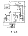
- Figure 5 is a block diagram showing a filtering system for liquid electrolyte; and
- Figures 6a and 6b show waveforms of pulses.
- Referring to Figs. 1 to 3, the
electrolytic finishing machine 1 has a work fixing device 3 in anelectrolyte tank 15. Awork 2 is mounted on abase 3a of the device 3 and fixed thereto by anupper plate 3b andbolts 16 screwed in thebase 3a. Anelectrode 4 is secured to the lower end of arod 17 of anelectrode holding device 5. The holding device is operatively connected to an electrode driving device 6 through an electrodedriving direction converter 7. Theconverter 7 is arranged to change rotary output of a motor 19 in device 6 into axial movement of therod 17. - The
work 2 has a three-dimensional recess 2a to be finished, which has been formed by an electrical discharge machine (not shown) with theelectrode 4. - As shown in Fig. 3, the driving device 6 has a
rotary encoder 20, tacho-generator 21 and motor 19. Output signals of theencoder 20 and tacho-generator 21 are supplied to amotor control section 9 of acontrol unit 12, and motor 19 is operated by a control signal from themotor control section 9. The control unit has a machiningcondition control section 10 and an electrolyteflow control section 11. - The system has a
power source device 8 which comprises a directcurrent source 22 and a charge/discharge section 23. The charge/discharge section 23 generates a pulse of a current density (specifically means "average current density") for a pulse duration dependent on the surface area of therecess 2a, in response to signals from the machiningcondition control section 10. - The system further has an
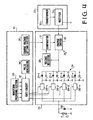
input device 13 for inputting machining conditions, and anelectrolyte filtering device 14. - Referring to Fig 4, the charge/
discharge section 23 has adischarge section 24 and a charge section 25. Thedischarge section 24 comprises a plurality of capacitors 26-1 to 26-n which are parallely connected with each other, diodes 27-1 to 27-n for preventing reverse current to the current source, and switches 28-1 to 28-n for generating pulses. The charge section 25 comprises avoltage detector 29 for detecting charge voltage applied to the capacitors 26-1 to 26-n, acomparator 31 for comprising a set voltage set at a charge voltage setting section 30 in machiningcondition control section 10 with the charge voltage detected by thevoltage detector 29, and a charge switch 32 responsive to a signal from thecomparator 31 for connecting the directcurrent source 22 to capacitors 26-1 to 26-n to charge each capacitor to a set value. The directcurrent source 22 comprises a transformer 33 and a rectifier 34. - The machining
condition control section 10 comprises awaveform providing section 35 for providing current waveform discharge in agap 18 between thework 2 and theelectrode 4, apulse generator 36 for generating pulses each having a predetermined pulse duration, agate circuit 37 for supplying an operation signal to switches 28-1 to 28-n in response to signals fromsection 35 andgenerator 36, and charge voltage setting section 30. There is provided adiode 38 for preventing the switches 28-1 to 28-n from breaking down by reverse current. - The
input device 13 is arranged to input various machining condition signals such as material of the work, surface area of the work, machining depth, grades of dimension accuracy, surface roughness, and dimension of thegap 18 between the electrode and the work. The signals are fed to themotor control section 9 and the machiningcondition control section 10. - Referring to Fig. 5, the
electrolyte filtering device 14 comprises adirty tank 42 for receiving electrolyte including residual products, which is removed from theelectrolyte tank 15, acentrifugal separator 45 which is driven by amotor 54 to separate the electrolyte fed through afilter 44 from thedirty tank 42 by apump 43,clean tank 46 storing clean electrolyte fed from thecentrifugal separator 45, apump 47 for feeding the electrolyte in theclean tank 46 to theelectrolyte tank 15 through a solenoid operatedvalve 50,flow metering valves 48 and 49 for adjusting the pressure of electrolyte fed to thetank 15, and apressure gauge 51. As shown in Fig. 3, thevalve 50 has anozzle 50a oriented to thegap 18. A pair of float switches 52 and 53 are provided for providing an upper and lower limits of electrolyte in thedirty tank 42. - The electrolyte
flow control section 11 is arranged to control theflow metering valves 48 and 49 to keep the pressure constant and to control the solenoid operatedvalve 50 in response to signals from the machiningcondition control section 10. - The machining method of the work is described hereinafter. The position of the
work 2 is adjusted by operating X and Y tables (not shown) to align therecess 2a with anelectrode surface 4a. Theelectrode 4 is lowered by the driving device 6 to contact thework 2 and the position of the electrode is stored as an original position A. Thereafter the electrode is raised to provide a predetermined initial gap. Electrolyte 41 (Fig. 3) is supplied to thetank 15, and electrolytic machining is started. In an initial state, a pulse having a current density between 10A/cm² and 70A/cm² (for example 17A/cm²) and a pulse duration shorter than 10 milli second (msec) is applied to theelectrode 4 by thepulse generator 8. In accordance with machining conditions such as area of the surface to be machined, current density, the number of capacitors 26-1 to 26-n is selected. By the electrolytic process, projected portions on the surface of therecess 2a are eroded, so that the height of each projection may be reduced. After one or more pulses are applied, theelectrode 4 is raised to expand thegap 18. Theelectrolyte 41 in thetank 15 is discharged to thedirty tank 42 together with residual products such as particles of eroded metal and hydrogen gas. At the same time as the discharge or after the discharge, the solenoid operatedvalve 50 is opened to inject clean electrolyte from the clean tank to thegap 18, thereby removing the residual products from the gap and thetank 15. - After the discharge of the electrolyte, the
electrode 4 is lowered to contact therecess 2a and the position of theelectrode 4 is stored. The stored position is compared with the original position A, so that the machining depth per one machining cycle (at every one or more pulses) is measured. Thereafter, theelectrode 4 is raised again to form the predetermined gap and clean electrolyte is supplied to thetank 15 by thepump 47 passing through a line 47a and flowmetering valve 48. Thus, the above described machining is repeated in accordance with signals from thecontrol unit 12. - When the difference between the sum of machining depth and the input depth becomes a predetermined value with respect to the input depth, (for example 1 µm), the short pulse duration (less than 10 msec) is increased to a long pulse duration (between 10 msec and 60 msec) by the signal from the machining
condition control section 10, and current density is also increased to a value higher than 30A/cm² and lower than 70A/cm². With the long pulse, the same electrolytic machining as the above described machining by the short pulse is performed. - By applying a short pulse of a lower current density, projections on the work surface are removed, and the surface are finished to a lustrous surface by a long pulse of higher current density. However, the same effect can be obtained by increasing only current density or only pulse duration.
- Although the pulse change timing is detected by machining depth in the above method, it can also be detected by calculating the accumulated amount of the current in coulomb until the machining ends.
- Fig. 6a shows a preferable pulse current density waveform. By keeping the current density at a rear portion R to a value higher than a set value, a lustrous surface can be obtained. As shown in Fig. 6b, if the current density at the R reduces, whole current density decreases, as a result lustrous surfaces can not be formed.
- The operation of the
electrolyte filtering device 14 will be described hereinafter. The level of the electrolyte in thedirty tank 42 is detected by float switches 52 and 53, and the detected level signal is applied to the electrolyteflow control section 11. When the level is between the switches, thecontrol section 11 produces a signal which operates thepump 43 to transfer the electrolyte to thecentrifugal separator 45 throughfilter 44. Thecentrifugal separator 45 is operated by themotor 54 to separate the residual products from the electrolyte. The clean electrolyte is stored in theclean tank 46. The electrolyte in thetank 46 is injected from thevalve 50 to thetank 15 and supplied to the tank through theflow metering valve 48 as described above. - The pressure of liquid electrolyte supplied from the
valve 48 is kept constant as described below. When the pressure measured by thepressure gauge 51 is lower than a set value of the electrolyteflow control section 11, the opening degree of theflow metering valve 48 is increased and the opening degree of the valve 49 in a return line is reduced, thereby increasing the pressure. When the measured pressure is higher than the set value, the opening degree ofvalve 48 is reduced and the opening degree of the valve 49 is increased. By keeping the pressure of electrolyte supplied to thetank 15, conditions of electrolyte, for example consumed time until the surface of the electrolyte becomes smooth, are maintained constant. Thus, the work is finished in high quality. As described above, the solenoid operatedvalve 50 injects the electrolyte into thegap 18 to remove the residual products in the gap together with the electrolyte. - Electrode : Copper
Stock Tool : steel (surface roughness of 20 µm)
Electrolyte : Sodium nitrate (concentration of 40%)
Pulse duration in early period : 3 msec
Current density in early period : 40A/cm²
Pulse duration in later period : 30 msec
Current density in later period : 40A/cm²
Finished surface roughness : Less than 1 µm
Finished surface : Lustrous surface
- Electrode : Copper
Stock Tool : steel (surface roughness 23 µm)
Electrolyte : Sodium nitrate (concentration 30%)
Pulse duration in early period : 5 msec
Current density in early period : 17 A/cm²
Pulse duration in later period : 10 msec
Current density in later period : 50A/cm²
Finished surface roughness : Less than 3 µm
Finished surface : Lustrous surface
- Electrode : Copper
Stock : Tool steel (surface roughness 20 µm)
Electrolyte : Sodium nitrate (concentration 40%)
Pulse duration in early period : 5 msec Current density in early period : 17 A/cm²
Pulse duration in later period : 5 msec
Current density in later period : 40A/cm²
Finished surface roughness : Less than 3 µm
Finished surface : Lustrous surface
- Although the pulse duration is changed once in the embodiment, it can be changed twice or more. For example, in early period, the pulse duration changed from 3 msec to 5 msec, and in later period, pulse duration is changed to three periods of 20 msec, 40 msec, and 60 msec. Similarly, current density can be preferably changed in several steps.
- The present invention can be used for finishing works other than the metal work, such as silicon single crystal for manufacturing semiconductors, gallium aersenide stock, and others.
- From the foregoing it will be understood that the electrolytic finishing is performed in stationary electrolyte by pulses. Accordingly, the machining is done under uniform concentration of electrolyte and constant condition during the electrolytic finishing, so that accurate products having high quality can be obtained. Since pulse duration and/or current density is increased in a later period of the process, the surface of the work can be finished to a lustrous surface.
- While the presently preferred embodiment of the present invention has been shown and described, it is to be understood that this disclosure is for the purpose of illustration and that various changes and modifications may be made without departing from the spirit and scope of the invention as set forth in the appended claim.
Claims (9)
an electrolyte tank;
supporting means for supporting an electrode adjacent a workpiece secured in the electrolyte tank;
driving means for moving the electrode with respect to the workpiece;
first means for intermittently applying pulses to the electrode positioned with a predetermined gap between the electrode and a surface of the workpiece;
second means for periodically removing electrolyte contaminated with residual products;
third means for cleaning the contaminated electrolyte; and
fourth means for returning the cleaned electrolyte to the electrolyte tank.
positioning an electrode to form a predetermined gap between the electrode and the surface of the work;
supplying electrolyte to an electrolyte tank so as to submerge the electrode and the work;
intermittently applying pulses to the electrode;
intermittently removing the electrolyte contaminated with residual products;
cleaning the contaminated electrolyte; and
resupplying the clean electrolyte to the electrolyte tank before the application of a pulse.
Applications Claiming Priority (6)
| Application Number | Priority Date | Filing Date | Title |
|---|---|---|---|
| JP61257071A JPH07251B2 (en) | 1986-10-30 | 1986-10-30 | Three-dimensional mirror finishing electrolytic processing method |
| JP257071/86 | 1986-10-30 | ||
| JP27616/87 | 1987-02-09 | ||
| JP62027616A JPH07108486B2 (en) | 1987-02-09 | 1987-02-09 | Finishing method and device by electrolytic processing |
| JP100291/87 | 1987-04-23 | ||
| JP62100291A JPS63267120A (en) | 1987-04-23 | 1987-04-23 | Finishing method by electrochemical machining |
Publications (3)
| Publication Number | Publication Date |
|---|---|
| EP0266180A2 true EP0266180A2 (en) | 1988-05-04 |
| EP0266180A3 EP0266180A3 (en) | 1989-03-08 |
| EP0266180B1 EP0266180B1 (en) | 1992-12-09 |
Family
ID=27285873
Family Applications (1)
| Application Number | Title | Priority Date | Filing Date |
|---|---|---|---|
| EP87309502A Expired - Lifetime EP0266180B1 (en) | 1986-10-30 | 1987-10-28 | Electrolytic finishing method |
Country Status (5)
| Country | Link |
|---|---|
| US (1) | US4800006A (en) |
| EP (1) | EP0266180B1 (en) |
| KR (1) | KR910000511B1 (en) |
| CA (1) | CA1321978C (en) |
| DE (1) | DE3783013T2 (en) |
Cited By (1)
| Publication number | Priority date | Publication date | Assignee | Title |
|---|---|---|---|---|
| US4880516A (en) * | 1987-06-23 | 1989-11-14 | Shizuoka Seiki Co., Ltd. | Electro-chemical machine |
Families Citing this family (9)
| Publication number | Priority date | Publication date | Assignee | Title |
|---|---|---|---|---|
| CA1328423C (en) * | 1987-09-17 | 1994-04-12 | Youhei Kuwabara | Electrolytic finishing method |
| EP0324142B1 (en) * | 1988-01-11 | 1992-03-11 | Shizuoka Seiki Co. Ltd. | Finishing method employing electrochemical machining and an electrochemical finishing machine |
| JPH01205918A (en) * | 1988-02-13 | 1989-08-18 | Shizuoka Seiki Co Ltd | Finishing work through electrolytic working |
| JPH0271932A (en) * | 1988-09-07 | 1990-03-12 | Shizuoka Seiki Co Ltd | Centering method for electrochemical finishing device |
| KR910018111A (en) * | 1990-04-26 | 1991-11-30 | 시기 모리야 | Electrolytic Processing Method and Electrolytic Processing Equipment |
| US6503387B2 (en) * | 2001-02-09 | 2003-01-07 | Industrial Technology Research Institute | Method and device for electro-chemical discharge processing with self-acting bubble layer |
| US6596152B2 (en) * | 2001-02-09 | 2003-07-22 | Industrial Technology Research Institute | Method and device for simultaneous arc processing and chemical etching |
| US20060144711A1 (en) * | 2002-11-08 | 2006-07-06 | Itsuki Kobata | Electrochemical machining device and electrochemical machining method |
| CN103008808B (en) * | 2012-12-26 | 2015-06-03 | 南京航空航天大学 | Numerical control electrolytic machining integrated control system and control method thereof |
Citations (3)
| Publication number | Priority date | Publication date | Assignee | Title |
|---|---|---|---|---|
| GB1050139A (en) * | 1900-01-01 | |||
| FR2473382A1 (en) * | 1980-01-09 | 1981-07-17 | Exnii Metallorezh Stankov | ELECTROCHEMICAL MACHINING PROCESS, DEVICE FOR ITS IMPLEMENTATION AND FACTORY PRODUCTS IN ACCORDANCE WITH THE METHOD |
| GB2081632A (en) * | 1980-08-05 | 1982-02-24 | Inoue Japax Res | Electrical discharge machining machine tool and method of operation |
Family Cites Families (5)
| Publication number | Priority date | Publication date | Assignee | Title |
|---|---|---|---|---|
| US3371022A (en) * | 1963-03-19 | 1968-02-27 | Inoue Kiyoshi | Low-electrolyte-pressure electro-chemical machining |
| US3527686A (en) * | 1965-12-06 | 1970-09-08 | Inoue K | Electrochemical machining apparatus and method |
| US3607689A (en) * | 1967-10-17 | 1971-09-21 | Inoue K | Power supply for large-surface electrochemical machining |
| GB1577766A (en) * | 1977-05-06 | 1980-10-29 | Rolls Royce | Electrolytic machining |
| SU1121116A1 (en) * | 1983-05-06 | 1984-10-30 | Московский Институт Радиотехники,Электроники И Автоматики | Method of electric discharge alloying |
-
1987
- 1987-10-22 US US07/111,237 patent/US4800006A/en not_active Expired - Lifetime
- 1987-10-28 CA CA000550499A patent/CA1321978C/en not_active Expired - Fee Related
- 1987-10-28 DE DE8787309502T patent/DE3783013T2/en not_active Expired - Fee Related
- 1987-10-28 EP EP87309502A patent/EP0266180B1/en not_active Expired - Lifetime
- 1987-10-29 KR KR1019870012019A patent/KR910000511B1/en not_active IP Right Cessation
Patent Citations (3)
| Publication number | Priority date | Publication date | Assignee | Title |
|---|---|---|---|---|
| GB1050139A (en) * | 1900-01-01 | |||
| FR2473382A1 (en) * | 1980-01-09 | 1981-07-17 | Exnii Metallorezh Stankov | ELECTROCHEMICAL MACHINING PROCESS, DEVICE FOR ITS IMPLEMENTATION AND FACTORY PRODUCTS IN ACCORDANCE WITH THE METHOD |
| GB2081632A (en) * | 1980-08-05 | 1982-02-24 | Inoue Japax Res | Electrical discharge machining machine tool and method of operation |
Cited By (1)
| Publication number | Priority date | Publication date | Assignee | Title |
|---|---|---|---|---|
| US4880516A (en) * | 1987-06-23 | 1989-11-14 | Shizuoka Seiki Co., Ltd. | Electro-chemical machine |
Also Published As
| Publication number | Publication date |
|---|---|
| KR910000511B1 (en) | 1991-01-26 |
| US4800006A (en) | 1989-01-24 |
| KR880005293A (en) | 1988-06-28 |
| CA1321978C (en) | 1993-09-07 |
| DE3783013D1 (en) | 1993-01-21 |
| EP0266180B1 (en) | 1992-12-09 |
| EP0266180A3 (en) | 1989-03-08 |
| DE3783013T2 (en) | 1993-04-15 |
Similar Documents
| Publication | Publication Date | Title |
|---|---|---|
| US4800006A (en) | Electrolytic finishing system and method | |
| US4097710A (en) | Method and apparatus for electrical machining | |
| US4885066A (en) | Electrolytic finishing method | |
| CA1325403C (en) | Method for finishing a work | |
| US4880516A (en) | Electro-chemical machine | |
| GB2093747A (en) | Electrode feed device for electrical machining apparatus | |
| US4956060A (en) | Finishing method employing electro-chemical machining, and an electro-chemical finishing machine | |
| US5028303A (en) | Electrolytic finishing method | |
| KR910006553B1 (en) | Electrolytic finishing method | |
| JPH07108486B2 (en) | Finishing method and device by electrolytic processing | |
| US4883568A (en) | Finishing method employing electro-chemical process | |
| GB2082954A (en) | Wire-cutting electroerosion machining method and apparatus | |
| JPS63306825A (en) | Machining gap control device for electro-chemical machine | |
| EP0389639A1 (en) | Centering method in an electrolytic finishing apparatus | |
| JPS63283818A (en) | Finishing method by electro-chemical machining | |
| SU1301594A1 (en) | Method of extremum control of electro-erosion process | |
| JPH07100259B2 (en) | Finishing method by electrolytic processing | |
| SU751552A1 (en) | Method of electrochemical working following electroerosion calibration | |
| JPH01252317A (en) | Electrolytic finish-machining method | |
| JPH012819A (en) | Processing tank of electrolytic processing equipment | |
| JPS63267118A (en) | Finishing method by electrochemical machining | |
| JPH02106222A (en) | Method of electrolytic finishing work | |
| JPH01228725A (en) | Working method of electrolytic finish | |
| JPH02109636A (en) | Electrolytic finishing method | |
| JPH01135418A (en) | Finishing method by electrochemical machining |
Legal Events
| Date | Code | Title | Description |
|---|---|---|---|
| PUAI | Public reference made under article 153(3) epc to a published international application that has entered the european phase |
Free format text: ORIGINAL CODE: 0009012 |
|
| 17P | Request for examination filed |
Effective date: 19871106 |
|
| AK | Designated contracting states |
Kind code of ref document: A2 Designated state(s): CH DE FR GB IT LI |
|
| PUAL | Search report despatched |
Free format text: ORIGINAL CODE: 0009013 |
|
| AK | Designated contracting states |
Kind code of ref document: A3 Designated state(s): CH DE FR GB IT LI |
|
| 17Q | First examination report despatched |
Effective date: 19910124 |
|
| GRAA | (expected) grant |
Free format text: ORIGINAL CODE: 0009210 |
|
| AK | Designated contracting states |
Kind code of ref document: B1 Designated state(s): CH DE FR GB IT LI |
|
| ET | Fr: translation filed | ||
| REF | Corresponds to: |
Ref document number: 3783013 Country of ref document: DE Date of ref document: 19930121 |
|
| ITF | It: translation for a ep patent filed |
Owner name: STUDIO CONS. BREVETTUALE S.R.L. |
|
| PLBE | No opposition filed within time limit |
Free format text: ORIGINAL CODE: 0009261 |
|
| STAA | Information on the status of an ep patent application or granted ep patent |
Free format text: STATUS: NO OPPOSITION FILED WITHIN TIME LIMIT |
|
| 26N | No opposition filed | ||
| PGFP | Annual fee paid to national office [announced via postgrant information from national office to epo] |
Ref country code: CH Payment date: 19950925 Year of fee payment: 9 |
|
| PGFP | Annual fee paid to national office [announced via postgrant information from national office to epo] |
Ref country code: GB Payment date: 19951025 Year of fee payment: 9 |
|
| PG25 | Lapsed in a contracting state [announced via postgrant information from national office to epo] |
Ref country code: GB Effective date: 19961028 |
|
| PG25 | Lapsed in a contracting state [announced via postgrant information from national office to epo] |
Ref country code: LI Effective date: 19961031 Ref country code: CH Effective date: 19961031 |
|
| REG | Reference to a national code |
Ref country code: CH Ref legal event code: PL |
|
| GBPC | Gb: european patent ceased through non-payment of renewal fee |
Effective date: 19961028 |
|
| PGFP | Annual fee paid to national office [announced via postgrant information from national office to epo] |
Ref country code: FR Payment date: 20000928 Year of fee payment: 14 |
|
| PGFP | Annual fee paid to national office [announced via postgrant information from national office to epo] |
Ref country code: DE Payment date: 20001031 Year of fee payment: 14 |
|
| PG25 | Lapsed in a contracting state [announced via postgrant information from national office to epo] |
Ref country code: FR Free format text: LAPSE BECAUSE OF NON-PAYMENT OF DUE FEES Effective date: 20020628 |
|
| PG25 | Lapsed in a contracting state [announced via postgrant information from national office to epo] |
Ref country code: DE Free format text: LAPSE BECAUSE OF NON-PAYMENT OF DUE FEES Effective date: 20020702 |
|
| REG | Reference to a national code |
Ref country code: FR Ref legal event code: ST |
|
| PG25 | Lapsed in a contracting state [announced via postgrant information from national office to epo] |
Ref country code: IT Free format text: LAPSE BECAUSE OF NON-PAYMENT OF DUE FEES;WARNING: LAPSES OF ITALIAN PATENTS WITH EFFECTIVE DATE BEFORE 2007 MAY HAVE OCCURRED AT ANY TIME BEFORE 2007. THE CORRECT EFFECTIVE DATE MAY BE DIFFERENT FROM THE ONE RECORDED. Effective date: 20051028 |