EP0265980B1 - Method and device to attach a strip of a flexible material to a fastening part, and its use in the fastening of a casing, e.g. a space balloon, to a fastening part - Google Patents
Method and device to attach a strip of a flexible material to a fastening part, and its use in the fastening of a casing, e.g. a space balloon, to a fastening part Download PDFInfo
- Publication number
- EP0265980B1 EP0265980B1 EP87201867A EP87201867A EP0265980B1 EP 0265980 B1 EP0265980 B1 EP 0265980B1 EP 87201867 A EP87201867 A EP 87201867A EP 87201867 A EP87201867 A EP 87201867A EP 0265980 B1 EP0265980 B1 EP 0265980B1
- Authority
- EP
- European Patent Office
- Prior art keywords
- fastening part
- annular
- housing
- longitudinal
- casing
- Prior art date
- Legal status (The legal status is an assumption and is not a legal conclusion. Google has not performed a legal analysis and makes no representation as to the accuracy of the status listed.)
- Expired - Lifetime
Links
Images


Classifications
-
- B—PERFORMING OPERATIONS; TRANSPORTING
- B64—AIRCRAFT; AVIATION; COSMONAUTICS
- B64B—LIGHTER-THAN AIR AIRCRAFT
- B64B1/00—Lighter-than-air aircraft
- B64B1/58—Arrangements or construction of gas-bags; Filling arrangements
-
- Y—GENERAL TAGGING OF NEW TECHNOLOGICAL DEVELOPMENTS; GENERAL TAGGING OF CROSS-SECTIONAL TECHNOLOGIES SPANNING OVER SEVERAL SECTIONS OF THE IPC; TECHNICAL SUBJECTS COVERED BY FORMER USPC CROSS-REFERENCE ART COLLECTIONS [XRACs] AND DIGESTS
- Y10—TECHNICAL SUBJECTS COVERED BY FORMER USPC
- Y10T—TECHNICAL SUBJECTS COVERED BY FORMER US CLASSIFICATION
- Y10T24/00—Buckles, buttons, clasps, etc.
- Y10T24/44—Clasp, clip, support-clamp, or required component thereof
- Y10T24/44034—Dissociable gripping members
Definitions
- the invention relates to a method of hooking, on a fastening piece, a strip made of a flexible material and in particular intended to be stressed longitudinally in tension. It applies to a method of hanging an envelope produced by means of a sheath made of a flexible material on a fixing piece and to a device for hanging an envelope on a fixing piece using this process.
- the invention applies, in particular, to the attachment of the envelope of a space balloon to fasteners located on the axis of this envelope and defining the upper and lower poles thereof.
- the constituent material (with asymmetric resistance higher in the longitudinal direction than in the circumferential direction) works in the best conditions, that is to say in each direction, at its elastic limit multiplied by a safety factor.
- the present invention proposes to provide a method for attaching an envelope to a fastener, which allows the recovery of significant efforts, while ensuring the tightness of the envelope, and which solve the above problems. above mentioned.
- the essential objective of the invention is to provide a method for attaching an envelope allowing the homogenization of the stresses in the different strands constituting the longitudinal chain of this envelope.
- Another objective of the invention is to reduce the intensity of the torsional stresses stressing the fasteners.
- Another object of the invention is to provide a method making it possible to simplify and make very precise the various operations allowing the attachment of an envelope to a fixing part.
- Another objective of the invention is to make it possible to control the characteristics of the attachment, before the envelope is inflated.
- Another objective is to provide a method for hooking on an attachment piece of the external longitudinal reinforcements allowing the transmission of rotational torques of the envelope.
- the method consists in folding the end of the strip at least twice on itself so as to produce at least a double hem, the last hem having a width (1) less than the width (L) of the previous one.
- the opposite faces of the hems and the opposite faces of two successive hems are preferably bonded together.
- the different folds of the hems can also advantageously be sewn together by means of threads made of a material with high tensile strength.
- a tensile force exerted on the strip causes compression of all the components of the block thanks to the seams and the bonding of the various plies and, consequently, a self-locking of the bead inside the housing of the fixing part. .
- a curable resin is advantageously injected into the housing of the fixing piece, after the bead has been put in place.
- this block of resin makes it possible to obtain at least a double wedge effect which results in an increase in the friction surfaces of the bead.
- the housing inside which the bead is disposed preferably has an axis of symmetry situated in the extension of the longitudinal axis of the strip.
- the various beads are therefore placed in the annular housing of the fixing part and then embedded in resin. hardenable so as to form a heel for the mechanical assembly.
- a multiplication of the number of these beads makes it possible to obtain a good definition of the system of revolution and the constitution of a homogeneous block with low angular pitch.
- the fixing piece is preferably removable in two annular pieces having opposite faces of shape adapted to form the annular housing, in the assembled position. said parts.
- the annular housing is also advantageously provided at the heart of the fixing part, and the assembly of the two annular parts is carried out by means of screwing members arranged on either side of said annular housing.
- This arrangement of the screwing members makes it possible to significantly reduce the mass of the fastening parts; the screwing members positioned on the external side guarantee, in effect, a rigid assembly of the annular parts during the tensioning of the envelope.
- the tightness of the envelope is, for its part, preferably ensured by a waterproof flap fixed, on the one hand, to the internal face of the envelope at the right of the end of the longitudinal slots so as to serve as a strip of tape. 'stopping said slots and, on the other hand, on the fixing piece.
- This watertight flap thus fulfills the dual function of a stop tape for longitudinal tears and a means of sealing the envelope. It can also be seen that the functions of mechanical resistance (transmission of longitudinal stresses) and sealing are fulfilled by separate elements. As a result, since the sealing is no longer ensured by the envelope itself, the problems posed by the production of longitudinal slots and the installation of screwing members on the external side of the annular housing are resolved.
- This process applies more particularly for the attachment of an envelope of generally cylindrical shape as described in French Patent No. 2,472,971 in the name of the applicant, that is to say carried out by the longitudinal assembly of N rectangular spindles of the same width.
- the method then consists in interrupting the assembly of said spindles at a determined distance from their longitudinal end in order to form a plurality of bands, and in shaping the extreme edge of each band so as to produce, in accordance with the method described above, a plurality of beads having a fan shape.
- each spindle can, moreover, also be divided into several strips of the same width separated by a longitudinal slit and the end edge of which is shaped so as to make a bead in the shape of a fan.
- This multiplication of the beads makes it possible, in fact, to obtain the constitution of a homogeneous block with a lower angular pitch.
- the main advantage of the process, in this particular application lies in the possibility of testing each zone individually. The manufacturing and safety constraints are therefore considerably reduced and the overall mechanical design of the attachment of the casing to a fixing piece is much healthier than for existing processes.
- the method allows, finally, the attachment to an annular fastening part of a network of reinforcements extending longitudinally along an envelope of generally cylindrical shape. It then consists in placing said reinforcements so that they form a radiating structure with crossed rays on the bottom of the envelope.
- the longitudinal network then allows the transmission to this envelope of pairs of rotations thereof.
- the hooking device shown by way of example in FIGS. 5 and 6 is intended for hooking the ends of a casing 1 to pole pieces arranged at the lower and upper poles of this casing, on the axis thereof. this. It applies in particular to the attachment, on pole pieces, of the ends of a space balloon envelope of generally cylindrical shape produced by the longitudinal assembly of N rectangular spindles.
- This envelope is composed of a composite material comprising a longitudinal chain in "Kevlar" and a circumferential weft in polyester, of a polyethylene outer film and polyester inner film.
- This device comprises a fixing part 2 of annular shape made of a rigid material.
- This fixing part is made up of two annular parts 3, 4 able to be assembled by means of fixing screws 5, 6.
- These two annular parts 3, 4 having assembly faces 3a, 4a facing each other, each provided with in their central zone, an annular groove 7 having the shape of a circular sector, the angles at the top of each groove 7 being identical and oriented on the peripheral wall 9 sides of the fixing piece 2.
- the fixing part 2 is provided with an annular housing 8 having a section having the shape of a circular sector whose axis of symmetry is orthogonal to the axis of the envelope 1.
- the fixing part 2 comprises an external peripheral face 9 provided with an annular slot opening into the aforementioned housing 8, towards the top of the latter.
- annular groove 10 formed on the assembly face 3a of one of them, internal side of the housing annular 8, inside which is housed an annular tenon 11 of conjugate shape, projecting from the assembly face 4a of the second part.
- a plurality of beads 12 are arranged in the form of fans of conjugate forms of this housing, and produced on the extreme edge of each spindle 13 constituting the envelope 1.
- these beads 12 is described below with reference to Figures 1, 2 and 3
- the different spindles 13 are arranged on an assembly table on which they are held in tension. These spindles 13 are then assembled longitudinally, this assembly being interrupted at a given distance from their longitudinal ends. They are then cut transversely at at least one of their longitudinal ends, so as to obtain spindles of strictly identical lengths.
- each spindle is then folded a first time on themselves in order to constitute a first hem (FIG. 1 a), then a second time in order to constitute a second hem 15 of width (1) less than the width (L ) of the first hem 14 (FIG. 1b).
- the widths (1) and (L) of the hems 14, 15 are perfectly determined by the use of two stops arranged successively in line with the longitudinal end of the spindle.
- each spindle 13 is gathered transversely, in an accordion fashion, so as to form a bead 12 in the form of a fan.
- the fan shape is obtained naturally, the second hem 15 having a width (1) less than that (L) of the first hem 14.
- the spindle 13 is provided transversely with at least two identical series of lights 16 made at predetermined distances from its longitudinal end.
- Each series is made up of lights 16 arranged at equidistant intervals corresponding to the width of the gathers of the fan ( Figure 2).
- the bead 12 being produced, it is redeployed in order to coat the various folds by means of a curable resin.
- the hems 14, 15 are then reconstituted and sewn by means of threads 17 in "Kevlar".
- the bead 12 is itself reconstituted and placed in a mold 18 of identical shape to the annular housing 8 of the fixing piece 2.
- the shape of this mold is adapted to obtain a tangency of the ends of the first hem 14 of two neighboring gathers. The relative position of the various gathers and, consequently, the overall shape of the bead 12, are therefore perfectly defined.
- this third hem makes it possible to obtain an additional wedge effect along the line C ′ in FIG. 3 and, consequently, constitutes an additional element aimed at guaranteeing the self-locking of the bead.
- this third hem makes it possible to subject each gathering of the bead to forces symmetrical with respect to the axis of the latter.
- the bead 12 forms a homogeneous block including all the friction surfaces are requested.
- the tensioning of the spindle 13 therefore causes compression of all the components of the bead 12 and the self-locking of the latter inside its housing.
- each time zone 13 can be tested individually before the envelope is attached to the fixing parts. The reliability of space balloons is therefore significantly increased.
- the plurality of beads being produced are arranged inside the annular housing 8 of the fastening pieces 2.
- the interstices separating these beads 12 are then filled by means of a hardenable resin injected via holes of injection formed in this fixing piece 2.
- the set of beads 12, embedded in the resin therefore forms a homogeneous block allowing the recovery of the stressing forces on the casing 1, by the fixing piece 2.
- each spindle 13 can be divided into several separate strips, over a length equivalent to the unassembled length of these spindles, by a longitudinal slot. Several identical beads 12 can thus be produced at the extreme edge of each spindle 13.
- this strip 19 is arranged in an annular groove 20 formed on the external peripheral face 9 of the fixing piece 2.
- the blocking of this strip 19 is ensured by the winding in this groove of a cable 21 of the type "Kevlar".
- the other end is, for its part, welded and then sewn onto the casing 1 and acts as a tear stop strip separating the different spindles 13.
- this waterproof film strip 19 is of an appropriate length to avoid its tensile stress when the envelope 1 is under tension.
- the attachment device illustrated in FIGS. 5 and 6 allows the attachment to the fixing part, of a controllable aerostatic balloon comprising an external envelope 1 containing air and as described above, a network of longitudinal reinforcements 22, a network of circumferential reinforcements (not shown), an internal envelope 23 containing a gas lighter than air and an interpolar link 24 connecting the lower and upper poles of the external envelope.
- the device comprises, for the attachment of the internal casing 23, a rim 25 made of a rigid material.
- This rim 25 is provided, on its external peripheral face 26, with an annular peripheral groove 27 inside which the end of the casing 23 is disposed.
- the blocking is ensured by the winding of a cable 28 made of a material that is not very stretchy and has a high tensile strength, of the "Kevlar" type.
- this rim 25 With a diameter less than the diameter of the fixing piece 2, this rim 25 is fixed concentrically to this piece by means of a ring 29 of intermediate diameter, secured to this rim 25 and to the fixing piece 2.
- the device also comprises means for hooking the longitudinal reinforcements 22, formed on the annular part 3 positioned outside the external envelope 1.
- These hooking means comprise an annular recess 30 formed on the external side of the face 31 , opposite the assembly face 3a, of this annular part 3.
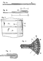
- a plurality of tenons such as 32 (FIG. 7).
- the longitudinal reinforcements 22 made up of endless cables produced by means of spliced and whipped "Kevlar” braids, are wound 180 degrees around the studs 32 and distributed so as to form a radiating structure with crossed rays on the bottom of the envelope. external 1 (figure 7). This arrangement allows the transmission to the casing 1 of torques for rotating the latter.
- the tenons 32 are covered by an annular cover 33 bearing on these tenons 32 and on the face 31, and fixed to the annular part 3 by means of fixing screws 34.
- the means for hooking the longitudinal reinforcements 22 on the fastener 2, described above can advantageously be replaced by the means for hooking shown in the figure 8.
- attachment means comprise a rim 41 made of a rigid material.
- This rim 41 is provided, on its external peripheral face 42, with an annular groove 43 inside which a cable 44 is wound in a material which is not very extensible and has a high tensile strength. Diameter greater than the diameter of the fixing piece, this rim is fixed concentrically on the latter not via radial arms 45, or by any other means known per se.
- peripheral edges 46 of this rim 41 are each provided with a plurality of studs 47.
- the attachment of the reinforcements 22 consists in placing the latter around the studs 47, as described above, their possible exhaust, after their installation. , being avoided by affixing covers 48.
- this attachment device comes from the fact that the reinforcements 22 are hung, alternately, on one and the other peripheral edge 46 of the rim 41. Thus, the rim subjected to symmetrical forces is not torsional stress.
- the fasteners 2 are, finally, provided with air intake and discharge means and also with helium intake and discharge means.
- the air intake and discharge means are provided on the fixing part 2 located at the lower pole of the envelope 1 (FIG. 6). To this end, the crown 29 forms an internal chamber 35 which communicates by lights 36 with the interior of the external envelope 1.
- the air supply duct 37 is equipped with a three-way valve (not shown) which makes it possible either to carry out an air evacuation, or to admit compressed air coming from a turbo-compressor (or other equivalent means).
- the internal envelope is inflated with helium through a conduit 38 which passes tightly through the crown 29 in order to open in an expansion chamber 39 an orifice 38a located on the axis of the balloon.
- this expansion chamber 39 communicates with the interior of this internal envelope through a grid 40 provided with lights of small section.
Abstract
Description
L'invention concerne un procédé d'accrochage, sur une pièce de fixation, d'une bande réalisée en un matériau souple et notamment destinée à être sollicitée longitudinalement en traction. Elle s'applique à un procédé d'accrochage d'une enveloppe réalisée au moyen d'une gaine en un matériau souple sur une pièce de fixation et à un dispositif d'accrochage d'une enveloppe sur une pièce de fixation mettant en oeuvre ce procédé.The invention relates to a method of hooking, on a fastening piece, a strip made of a flexible material and in particular intended to be stressed longitudinally in tension. It applies to a method of hanging an envelope produced by means of a sheath made of a flexible material on a fixing piece and to a device for hanging an envelope on a fixing piece using this process.
L'invention s'applique, en particulier, à l'accrochage de l'enveloppe d'un ballon spatial sur des pièces de fixation situées sur l'axe de cette enveloppe et définissant les pôles supérieur et inférieur de celle-ci.The invention applies, in particular, to the attachment of the envelope of a space balloon to fasteners located on the axis of this envelope and defining the upper and lower poles thereof.
Les travaux effectués dans le domaine des ballons spatiaux ont conduit à la réalisation de ballons de forme générale cylindrique supportant des surpressions très élevées. En effet, la tenue de la surpression sur les fonds du cylindre est assurée par l'effet simultané de trois actions : l'action de l'enveloppe elle-même, l'action d'un lien interpolaire reliant les deux pôles de l'enveloppe, et l'action d'un réseau externe de renforts longitudinaux. La tenue de la surpression par la paroi cylindrique est quant à elle assurée par la réalisation de lobes longitudinaux séparés par un réseau de renforts circonférentiels assurant, en outre, la reprise de la composante radiale de la tension longitudinale. Des méthodes de calcul éprouvées permettent, dans chaque application, d'ajuster les différents paramètres (densité du réseau circonférentiel, densité du réseau longitudinal...) de façon à optimiser le champ de contraintes s'appliquant sur les enveloppes. La maîtrise de ces différents paramètres permet ainsi la réalisation d'enveloppes souples à haute surpression dont la matériau constitutif (à résistance dissymétrique plus élevée dans le sens longitudinal que dans le sens circonférentiel) travaille dans les meilleures conditions, c'est-à-dire dans chaque direction, à sa limite élastique multipliée par un coefficient de sécurité.The work carried out in the field of space balloons has led to the production of balloons of generally cylindrical shape supporting very high overpressures. Indeed, the holding of the overpressure on the cylinder bottoms is ensured by the simultaneous effect of three actions: the action of the envelope itself, the action of an interpolar link connecting the two poles of the envelope, and the action of an external network of longitudinal reinforcements. Holding the overpressure by the cylindrical wall is provided by the production of longitudinal lobes separated by a network of circumferential reinforcements ensuring, in addition, the recovery of the radial component of the longitudinal tension. Proven calculation methods make it possible, in each application, to adjust the different parameters (density of the circumferential network, density of the longitudinal network, etc.) so as to optimize the stress field applying to the envelopes. The control of these different parameters thus allows the production of flexible envelopes with high overpressure, the constituent material (with asymmetric resistance higher in the longitudinal direction than in the circumferential direction) works in the best conditions, that is to say in each direction, at its elastic limit multiplied by a safety factor.
En fait, à l'heure actuelle, seules subsistent des difficultés relatives à l'accrochage des extrémités de l'enveloppe sur les pièces polaires, qui nécessite une étude particulière pour résoudre les problèmes d'interface entre des structures souples et des structures rigides devant supporter des contraintes très importantes. Les différents dispositif d'accrochage existants nécessitent en effet de surdi- mensionner les pièces polaires du fait des couples de torsion importants auxquels celles-ci sont soumises. De plus, et surtout, ces dispositifs nécessitent la réalisation d'un bourrelet de blocage sur le bord extrême de l'enveloppe. Or, la définition géométrique de ce bourrelet étant rarement parfaite, les différents brins constituant la chaîne longitudinale de l'enveloppe sont soumis à des efforts longitudinaux différents, et il s'ensuit la création d'efforts de cisaillement difficilement paramétrables.In fact, at present, only difficulties remain relating to the attachment of the ends of the envelope to the pole pieces, which requires a particular study to resolve the interface problems between flexible structures and rigid structures in front of bear very significant constraints. The various existing hooking devices indeed require oversizing the pole pieces because of the high torsional torques to which they are subjected. In addition, and above all, these devices require the production of a locking bead on the extreme edge of the envelope. However, the geometric definition of this bead is rarely perfect, the different strands constituting the longitudinal chain of the envelope are subjected to different longitudinal forces, and it follows the creation of shear forces which are difficult to configure.
De tels inconvénients se retrouvent également dans les dispositifs tels que décrits dans le brevet US 2 759 692 correspondant aux préambules des revendications 1 et 16, respectivement, dans lesquels l'extrémité de l'enveloppe est maintenue coincée entre deux pièces annulaires autour desquelles et entre lesquelles elle est enroulée. En effet, le bord extrême de l'enveloppe est alors maintenu par frottement entre les deux pièces annulaires, ce qui ne permet pas en pratique de résoudre les problèmes d'interface entre des structures souples et des structures rigides devant supporter des contraintes importantes.Such drawbacks are also found in the devices as described in US Pat. No. 2,759,692 corresponding to the preambles of
La présente invention se propose de fournir un procédé pour l'accrochage d'une enveloppe sur une pièce de fixation, qui permet la reprise d'efforts importants, tout en assurant l'étanchéité de l'enveloppe, et qui solutionnent les problèmes ci-dessus évoqués.The present invention proposes to provide a method for attaching an envelope to a fastener, which allows the recovery of significant efforts, while ensuring the tightness of the envelope, and which solve the above problems. above mentioned.
A cet effet, l'objectif essentiel de l'invention est de fournir un procédé pour l'accrochage d'une enveloppe permettant l'homogénéisation des contraintes dans les différents brins constituant la chaîne longitudinale de cette enveloppe.To this end, the essential objective of the invention is to provide a method for attaching an envelope allowing the homogenization of the stresses in the different strands constituting the longitudinal chain of this envelope.
Un autre objectif de l'invention est de réduire l'intensité des contraintes de torsion sollicitant les pièces de fixation.Another objective of the invention is to reduce the intensity of the torsional stresses stressing the fasteners.
Un autre objectif de l'invention est de fournir un procédé permettant de simplifier et de rendre très précises les différentes opérations permettant l'accrochage d'une enveloppe sur une pièce de fixation.Another object of the invention is to provide a method making it possible to simplify and make very precise the various operations allowing the attachment of an envelope to a fixing part.
Un autre objectif de l'invention est de permettre de contrôler les caractéristiques de l'accrochage, avant le gonflage de l'enveloppe.Another objective of the invention is to make it possible to control the characteristics of the attachment, before the envelope is inflated.
Un autre objectif est de fournir un procédé pour l'accrochage sur une pièce de fixation des renforts longitudinaux externes permettant la transmission de couples de mise en rotation de l'enveloppe.Another objective is to provide a method for hooking on an attachment piece of the external longitudinal reinforcements allowing the transmission of rotational torques of the envelope.
Le procédé conforme à l'invention permet l'accrochage d'une extrémité longitudinale d'une bande en un matériau souple, sur une pièce de fixation, et est caractérisé en ce qu'il consiste:
- - à replier longitudinalement ladite extrémité sur elle-même au moins une fois, de façon à réaliser au moins un ourlet,
- - à froncer transversalement en accordéon, l'extrémité ourlée de façon à réaliser un bourrelet présentant une forme en éventail,
- - à utiliser une pièce de fixation dotée d'un logement présentant une section longitudinale de forme évasée conjuguée de la forme du bourrelet, ledit logement possédant une extrémité longitudinale ouverte, vers son sommet,
- - à disposer le bourrelet dans le logement précité de la pièce de fixation, la bande s'étendant hors dudit logement par l'extrémité ouverte de ce dernier, de façon à entraîner un auto-blocage du bourrelet lors de la mise en tension de la bande.
- - folding said end longitudinally on itself at least once, so as to produce at least one hem,
- - to gather transversely in accordion, the hemmed end so as to produce a bead having a fan shape,
- to use a fixing piece provided with a housing having a longitudinal section of flared shape combined with the shape of the bead, said housing having an open longitudinal end, towards its top,
- - To have the bead in the aforementioned housing of the fixing piece, the strip extending out of said housing by the open end of the latter, so as to cause a self-locking of the bead when the tensioning of the bandaged.
Préférentiellement, le procédé consiste à replier l'extrémité de la bande au moins deux fois sur elle-même de façon à réaliser au moins un double ourlet, le dernier ourlet présentant une largeur (1) inférieure à la largeur (L) du précédent.Preferably, the method consists in folding the end of the strip at least twice on itself so as to produce at least a double hem, the last hem having a width (1) less than the width (L) of the previous one.
La réalisation d'au moins un double ourlet de largeur décroissante permet, notamment lors du fronçage de la bande, d'obtenir naturellement la forme en éventail du bourrelet.The production of at least one double hem of decreasing width makes it possible, in particular when gathering the strip, to naturally obtain the fan-shaped shape of the bead.
Ce procédé autorise une modélisation totale de toutes les opérations effectuées qui permet d'optimiser les formes et de trouver le meilleur compromis pour résoudre les problèmes d'interface. En outre, la géométrie du bourrelet étant parfaitement définie, les différents brins constitutifs de la chaîne longitudinale de la bande sont sollicités indépendamment les uns des autres et sont soumis aux mêmes efforts de traction, d'où la suppression de tout effort de cisaillement entre brins.This process allows a total modeling of all the operations performed which allows opti bet the forms and find the best compromise to solve interface problems. In addition, the geometry of the bead being perfectly defined, the different strands constituting the longitudinal chain of the strip are stressed independently of each other and are subjected to the same tensile forces, hence the elimination of any shear force between strands .
Afin d'obtenir une meilleure transmission des efforts sollicitant les extrémités des plis, les faces en regard des ourlets et les faces en regard de deux ourlets successifs sont préférentiellement collées entre elles. Les différents plis des ourlets peuvent également être avantageusement cousus ensemble au moyen de fils en un matériau à haute résistance à la traction. Ainsi, un effort de traction exercé sur la bande entraîne une compression de tous les composants du bloc grâce aux coutures et au collage des différents plis et, par conséquent, un auto-blocage du bourrelet à l'intérieur du logement de la pièce de fixation.In order to obtain a better transmission of the forces stressing the ends of the folds, the opposite faces of the hems and the opposite faces of two successive hems are preferably bonded together. The different folds of the hems can also advantageously be sewn together by means of threads made of a material with high tensile strength. Thus, a tensile force exerted on the strip causes compression of all the components of the block thanks to the seams and the bonding of the various plies and, consequently, a self-locking of the bead inside the housing of the fixing part. .
En outre, si les efforts de frottement entre les différents plis des ourlets s'avèrent insuffisants pour permettre un auto-blocage du bourrelet, une résine durcissable est avantageusement injectée dans le logement de la pièce de fixation, après la mise en place du bourrelet. Comme on le comprendra mieux plus loin, ce bloc de résine permet d'obtenir au moins un double effet de coin qui entraîne une augmentation des surfaces de frottement du bourrelet.In addition, if the friction forces between the various folds of the hems prove to be insufficient to allow self-locking of the bead, a curable resin is advantageously injected into the housing of the fixing piece, after the bead has been put in place. As will be better understood below, this block of resin makes it possible to obtain at least a double wedge effect which results in an increase in the friction surfaces of the bead.
Ce bourrelet, noyé dans son bloc de résine, forme donc le talon de reprise des efforts sollicitant la bande, par l'ensemble mécanique rigide que forme la pièce de fixation. Afin de diminuer les dimensions de cette dernière, le logement à l'intérieur duquel est disposé le bourrelet présente, préférentiellement, un axe de symétrie situé dans le prolongement de l'axe longitudinal de la bande. Ainsi, lors d'une mise en tension de cette bande, la pièce de fixation n'est soumise à aucun couple de torsion.This bead, embedded in its block of resin, therefore forms the heel for resuming the forces urging the strip, by the rigid mechanical assembly formed by the fixing piece. In order to reduce the dimensions of the latter, the housing inside which the bead is disposed preferably has an axis of symmetry situated in the extension of the longitudinal axis of the strip. Thus, during a tensioning of this strip, the fastener is not subjected to any torque.
Le procédé s'applique pour l'accrochage d'une enveloppe réalisée au moyen d'une gaine en un matériau souple, sur une pièce de fixation. Il consiste alors :
- - à fendre longitudinalement sur une longueur donnée et à intervalles équidistants, une portion extrême de ladite gaine, afin de former une pluralité de bandes,
- - à former, conformément au procédé décrit ci-dessus, un bourrelet présentant la forme d'un éventail au niveau du bord extrême de chaque bande ainsi réalisée,
- - à utiliser une pièce de fixation annulaire réalisée au moyen d'un matériau rigide et possédant un logement annulaire présentant une section ayant la forme d'un secteur circulaire conjugué de la forme des bourrelets, ledit logement étant doté, vers son sommet, d'une ouverture débouchant au niveau de la paroi périphérique de la pièce de fixation, sur tout le pourtour de celle-ci,
- - à disposer les différents bourrelets les uns à côté des autres à l'intérieur du logement précité de la pièce de fixation.
- - to split longitudinally over a given length and at equidistant intervals, an extreme portion of said sheath, in order to form a plurality of bands,
- to form, in accordance with the method described above, a bead having the shape of a fan at the end edge of each strip thus produced,
- - To use an annular fixing part made by means of a rigid material and having an annular housing having a section having the shape of a circular sector conjugate with the shape of the beads, said housing being provided, towards its top, with an opening opening at the peripheral wall of the fastener, around the entire periphery thereof,
- - Arrange the different beads one next to the other inside the aforementioned housing of the fixing piece.
Les différents bourrelets sont donc disposés dans le logement annulaire de la pièce de fixation puis noyés dans de la résine. durcissable de façon à former un talon de reprise par l'ensemble mécanique. En outre, une multiplication du nombre de ces bourrelets permet d'obtenir une bonne définition du système de révolution et la constitution d'un bloc homogène à faible pas angulaire.The various beads are therefore placed in the annular housing of the fixing part and then embedded in resin. hardenable so as to form a heel for the mechanical assembly. In addition, a multiplication of the number of these beads makes it possible to obtain a good definition of the system of revolution and the constitution of a homogeneous block with low angular pitch.
Par ailleurs, afin de faciliter la mise en place des différents bourrelets à l'intérieur du logement annulaire, la pièce de fixation est préférentiellement démontable en deux pièces annulaires possédant des faces en regard de forme adaptées pour former le logement annulaire, dans la position assemblée desdites pièces.Furthermore, in order to facilitate the positioning of the various beads inside the annular housing, the fixing piece is preferably removable in two annular pieces having opposite faces of shape adapted to form the annular housing, in the assembled position. said parts.
Le logement annulaire est, en outre, avantageusement ménagé au coeur de la pièce de fixation, et l'assemblage des deux pièces annulaires est réalisé au moyen d'organes de vissage disposés de part et d'autre dudit logement annulaire. Cette disposition des organes de vissage permet de diminuer notablement la masse des pièces de fixation ; les organes de vissage positionnés du côté externe garantissent, en effet, un assemblage rigide des pièces annulaires lors de la mise en tension de l'enveloppe.The annular housing is also advantageously provided at the heart of the fixing part, and the assembly of the two annular parts is carried out by means of screwing members arranged on either side of said annular housing. This arrangement of the screwing members makes it possible to significantly reduce the mass of the fastening parts; the screwing members positioned on the external side guarantee, in effect, a rigid assembly of the annular parts during the tensioning of the envelope.
Cette diminution de la masse de la pièce de fixation est également favorisée par la disposition du logement annulairement qui possède, avantageusement, un plan de symétrie transversal sensiblement orthogonal à l'axe de la gaine. Lors de la mise en tension de l'enveloppe, la pièce de fixation n'est donc soumise à aucun couple de torsion.This reduction in the mass of the fixing part is also favored by the arrangement of the annular housing which advantageously has a plane of transverse symmetry substantially orthogonal to the axis of the sheath. When the envelope is tensioned, the fastening part is therefore not subjected to any torque.
L'étanchéité de l'enveloppe est, quant à elle, préférentiellement assurée par une bavette étanche fixée, d'une part, sur la face interne de l'enveloppe au droit de l'extrémité des fentes longitudinales de façon à servir de bande d'arrêt desdites fentes et, d'autre part, sur la pièce de fixation. Cette bavette étanche remplit ainsi la double fonction de bande d'arrêt des déchirures longitudinales et de moyen d'étanchéité de l'enveloppe. On constate, par ailleurs, que les fonctions de résistance mécanique (transmission des contraintes longitudinales) et d'étanchéité sont remplies par des éléments distincts. De ce fait, l'étanchéité n'étant plus assurée par l'enveloppe elle-même, les problèmes posés par la réalisation de fentes longitudinales et la mise en place d'organes de vissage du côté externe du logement annulaire se trouvent résolus.The tightness of the envelope is, for its part, preferably ensured by a waterproof flap fixed, on the one hand, to the internal face of the envelope at the right of the end of the longitudinal slots so as to serve as a strip of tape. 'stopping said slots and, on the other hand, on the fixing piece. This watertight flap thus fulfills the dual function of a stop tape for longitudinal tears and a means of sealing the envelope. It can also be seen that the functions of mechanical resistance (transmission of longitudinal stresses) and sealing are fulfilled by separate elements. As a result, since the sealing is no longer ensured by the envelope itself, the problems posed by the production of longitudinal slots and the installation of screwing members on the external side of the annular housing are resolved.
Ce procédé s'applique plus particulièrement pour l'accrochage d'une enveloppe de forme générale cylindrique telle que décrite dans le brevet français n° 2 472 971 au nom du demandeur, c'est-à-dire réalisée par l'assemblage longitudinal de N fuseaux rectangulaires de même largeur. Le procédé consiste alors à interrompre l'assemblage desdits fuseaux à une distance déterminée de leur extrémité longitudinale afin de former une pluralité de bandes, et à façonner le bord extrême de chaque bande de façon à réaliser, conformément au procédé décrit ci-dessus, une pluralité de bourrelets présentant une forme en éventail.This process applies more particularly for the attachment of an envelope of generally cylindrical shape as described in French Patent No. 2,472,971 in the name of the applicant, that is to say carried out by the longitudinal assembly of N rectangular spindles of the same width. The method then consists in interrupting the assembly of said spindles at a determined distance from their longitudinal end in order to form a plurality of bands, and in shaping the extreme edge of each band so as to produce, in accordance with the method described above, a plurality of beads having a fan shape.
La portion extrême de chaque fuseau peut, en outre, être également divisée en plusieurs bandes de même largeur séparées par une fente longitudinale et dont le bord extrême est façonné de façon à réaliser un bourrelet en forme d'éventail. Cette multiplication des bourrelets permet, en effet, d'obtenir la constitution d'un bloc homogène à plus faible pas angulaire. Mais le principal avantage du procédé, dans cette application particulière, réside dans la possibilité de tester individuellement chaque fuseau. Les contraintes de fabrication et de sécurité sont donc notablement diminuées et la conception mécanique globale de l'accrochage de l'enveloppe sur une pièce de fixation est beacoup plus saine que pour les procédés existants.The end portion of each spindle can, moreover, also be divided into several strips of the same width separated by a longitudinal slit and the end edge of which is shaped so as to make a bead in the shape of a fan. This multiplication of the beads makes it possible, in fact, to obtain the constitution of a homogeneous block with a lower angular pitch. But the main advantage of the process, in this particular application, lies in the possibility of testing each zone individually. The manufacturing and safety constraints are therefore considerably reduced and the overall mechanical design of the attachment of the casing to a fixing piece is much healthier than for existing processes.
Le procédé permet, enfin, l'accrochage sur une pièce de fixation annulaire d'un réseau de renforts s'étendant longitudinalement le long d'une enveloppe de forme générale cylindrique. Il consiste alors à disposer lesdits renforts de façon qu'ils forment une structure rayonnante à rayons croisés sur le fond de l'enveloppe. Le réseau longitudinal permet alors la transmission à cette enveloppe de couples de mises en rotation de celle-ci.The method allows, finally, the attachment to an annular fastening part of a network of reinforcements extending longitudinally along an envelope of generally cylindrical shape. It then consists in placing said reinforcements so that they form a radiating structure with crossed rays on the bottom of the envelope. The longitudinal network then allows the transmission to this envelope of pairs of rotations thereof.
L'accrochage du réseau de renforts, sur la pièce de fixation, peut consister avantageusement:
- - à utiliser une jante annulaire comprenant une face périphérique externe dotée d'une gorge annulaire et des chants périphériques dotés chacun de tenons,
- - à fixer la jante précitée concentriquement autour de la pièce de fixation,
- - à accrocher les renforts longitudinaux, alternativement, sur les tenons de l'un et l'autre chant périphérique de la jante,
- - à disposer dans la gorge annulaire de la jante un collier de serrage réalisé en un matériau peu extensible de haute résistance à la traction en vue de reprendre les efforts longitudinaux sollicitant les renforts, par la mise en tension dudit collier de serrage.
- to use an annular rim comprising an external peripheral face provided with an annular groove and peripheral edges each provided with pins,
- - to fix the aforementioned rim concentrically around the fixing piece,
- - to hang the longitudinal reinforcements, alternately, on the lugs of one and the other peripheral edge of the rim,
- - To have in the annular groove of the rim a clamp made of a poorly extensible material of high tensile strength in order to take up the longitudinal forces requesting the reinforcements, by tensioning said clamp.
Ce mode opératoire présente trois avantages essentiels qui autorisent la reprise de tensions longitudinales très élevées:
- - reprise des efforts longitudinaux sollicitant les renforts par le collier de serrage mis en tension suivant sa direction préférentielle de déformation,
- - forme annulaire de la jante qui entraîne un auto- équilibrage des efforts sollicitant le collier de serrage: les efforts transmis à la pièce de fixation sont donc très faibles,
- - accrochage des renforts, alternativement, sur l'un et l'autre chant périphérique, qui permet de soumettre la jante à des efforts symétriques, évitant sa sollicitation en torsion.
- resumption of the longitudinal forces requesting the reinforcements by the clamping collar tensioned in its preferred direction of deformation,
- - annular shape of the rim which results in self-balancing of the forces stressing the clamp: the forces transmitted to the fastening part are therefore very low,
- - attachment of the reinforcements, alternately, on one and the other peripheral edge, which allows the rim to be subjected to symmetrical forces, avoiding its torsional stress.
D'autres caractéristiques, buts et avantages de l'invention se dégageront de la description détaillée qui suit et de l'examen des dessins annexés qui en présentent, à titre d'exemple non limitatif, un mode de réalisation préférentiel. Sur ces dessins qui font partie intégrante de la description:
- - les figures 1 a et 1 b sont des coupes schématiques à échelle dilatée illustrant la réalisation d'un double ourlet conformément au procédé de l'invention,
- - la figure 2 est une vue en plan partielle de la portion extrême de l'enveloppe telle que préparée en vue de réaliser son fronçage,
- - la figure 3 est une coupe transversale à échelle dilatée d'un bourrelet en forme d'éventail conforme à l'invention,
- - la figure 4 est une coupe schématique à échelle dilatée illustrant la réalisation d'un triple ourlet,
- - la figure 5 est une coupe longitudinale d'un dispositif d'accrochage d'une enveloppe sur une pièce de fixation située au niveau du pôle supérieur de cette enveloppe,
- - la figure 6 est une coupe longitudinale d'un dispositif d'accrochage d'une enveloppe sur une pièce de fixation située au niveau du pôle inférieur de l'enveloppe,
- - la figure 7 est une demi-coupe transversale par un plan A-A représentant des moyens d'accrochage du réseau de renforts longitudinaux de cette enveloppe,
- - la figure 8 est une coupe longitudinale représentant un deuxième mode de réalisation des moyens d'accrochage des renforts longitudinaux.
- FIGS. 1 a and 1 b are schematic sections on an expanded scale illustrating the production of a double hem according to the method of the invention,
- FIG. 2 is a partial plan view of the extreme portion of the envelope as prepared for its gathering,
- FIG. 3 is a cross section on an expanded scale of a fan-shaped bead according to the invention,
- FIG. 4 is a diagrammatic section on an expanded scale illustrating the production of a triple hem,
- FIG. 5 is a longitudinal section of a device for hanging an envelope on a fastening part located at the upper pole of this envelope,
- FIG. 6 is a longitudinal section of a device for hanging an envelope on a fixing piece located at the lower pole of the envelope,
- FIG. 7 is a half cross-section through a plane AA representing means for hooking the network of longitudinal reinforcements of this envelope,
- - Figure 8 is a longitudinal section showing a second embodiment of the attachment means of the longitudinal reinforcements.
Le dispositf d'accrochage représenté à titre d'exemple aux figures 5 et 6 est destiné à l'accrochage des extrémités d'une enveloppe 1 sur des pièces polaires disposées aux pôles inférieur et supérieur de cette enveloppe, sur l'axe de celle-ci. Il s'applique en particulier à l'accrochage, sur des pièces polaires, des extrémités d'une enveloppe de ballon spatial de forme générale cylindrique réalisée par l'assemblage longitudinal de N fuseaux rectangulaires.The hooking device shown by way of example in FIGS. 5 and 6 is intended for hooking the ends of a casing 1 to pole pieces arranged at the lower and upper poles of this casing, on the axis thereof. this. It applies in particular to the attachment, on pole pieces, of the ends of a space balloon envelope of generally cylindrical shape produced by the longitudinal assembly of N rectangular spindles.
Cette enveloppe 1, telle que par exemple décrite dans la demande de brevet EP-A 0 184 262 au nom du demandeur, est composée d'un matériau composite comprenant une chaîne longitudinale en "Kevlar" et une trame circonférentielle en polyester, d'un film extérieur en polyéthylène et d'un film intérieur en polyester.This envelope 1, as for example described in patent application EP-A 0 184 262 in the name of the applicant, is composed of a composite material comprising a longitudinal chain in "Kevlar" and a circumferential weft in polyester, of a polyethylene outer film and polyester inner film.
Ce dispositif comprend une pièce de fixation 2 de forme annulaire réalisée en un matériau rigide. Cette pièce de fixation est constituée de deux pièces annulaires 3, 4 aptes à être assemblées au moyen de vis de fixation 5, 6. Ces deux pièces annulaires 3, 4 possédant des faces d'assemblage 3a, 4a en regard, dotées, chacune, dans leur zone centrale, d'une gorge annulaire 7 présentant la forme d'un secteur circulaire, les angles au sommet de chaque gorge 7 étant identiques et orientés côtés paroi périphérique 9 de la pièce de fixation 2. Ainsi, dans la position assemblée de ces deux pièces annulaires 3, 4, la pièce de fixation 2 est dotée d'un logement annulaire 8 présentant une section ayant la forme d'un secteur circulaire dont l'axe de symétrie est orthogonal à l'axe de l'enveloppe 1. En outre, la pièce de fixation 2 comprend une face périphérique externe 9 dotée d'une fente annulaire débouchant dans le logement 8 précité, vers le sommet de ce dernier.This device comprises a fixing
Par ailleurs, un positionnement correct des deux pièces annulaires 3, 4 en regard l'une de l'autre, est assuré par une gorge annulaire 10 ménagée sur la face d'assemblage 3a de l'une d'elles, côté interne du logement annulaire 8, à l'intérieur de laquelle vient se loger un tenon annulaire 11 de forme conju- gée, en saillie sur la face d'assemblage 4a de la deuxième pièce.Furthermore, correct positioning of the two
Une fois leur positionnement assuré, l'assemblage de ces deux pièces annulaires 3, 4 est obtenu au moyen de vis de fixation 5, 6 aptes à être vissées dans des alésages taraudés ménagés de part et d'autre du logement annulaire 8.Once their positioning has been secured, the assembly of these two
Dans le logement annulaire 8, sont disposés une pluralité de bourrelets 12 en forme d'éventails de formes conjugées de ce logement, et réalisés sur le bord extrême de chaque fuseau 13 constituant l'enveloppe 1.In the
Le mode de réalisation de ces bourrelets 12 est décrit ci-après en référence aux figures 1, 2 et 3 Dans une phase préliminaire, les différents fuseaux 13 sont disposés sur une table d'assemblage sur laquelle ils sont maintenus en tension. Ces fuseaux 13 sont ensuite assemblés longitudinalement, cet assemblage étant interrompu à une distance donnée de leurs extrémités longitudinales. Ils sont ensuite découpés transversalement au niveau d'au moins une de leurs extrémités longitudinales, de façon à obtenir des fuseaux de longueurs strictement identiques.The embodiment of these
Les bords extrêmes de chaque fuseau sont ensuite repliés une première fois sur eux-mêmes afin de constituer un premier ourlet (figure 1 a), puis une deuxième fois afin de constituer un deuxième ourlet 15 de largeur (1) inférieure à la largeur (L) du premier ourlet 14 (figure 1b). L ors de ces opérations de pliage, les largeurs (1) et (L) des ourlets 14, 15 sont parfaitement déterminées par l'utilisation de deux butées disposées successivement au droit de l'extrémité longitudinale du fuseau.The extreme edges of each spindle are then folded a first time on themselves in order to constitute a first hem (FIG. 1 a), then a second time in order to constitute a
Une fois le double ourlet 14, 15 réalisé, le bord extrême de chaque fuseau 13 est froncé transversalement, en accordéon, de façon à former un bourrelet 12 en forme d'éventail. Lors de ce plissage, la forme en éventail est obtenue naturellement, le deuxième ourlet 15 présentant une largeur (1) inférieure à celle (L) du premier ourlet 14.Once the
En outre, afin d'obtenir un éventail de forme régulière dont les différentes fronces sont de même largeur, le fuseau 13 est doté transversalement d'au moins deux séries identiques de lumières 16 pratiquées à des distances déterminées de son extrémité longitudinale. Chaque série est composée de lumières 16 disposées à intervalles équidistants correspondant à la largeur des fronces de l'éventail (figure 2). Ainsi, lors du plissage, il suffit d'utiliser un gabarit doté de deux tiges espacées d'une longueur équivalente à la distance séparant les deux séries de lumières 16 ; la réalisation des différentes fronces est alors obtenue en positionnant successivement les lumières 16 en vis-à-vis des deux séries sur les tiges du gabarit.In addition, in order to obtain a fan of regular shape whose different gathers are of the same width, the
Le bourrelet 12 étant réalisé, celui-ci est redéplié afin d'enduire les différents plis au moyen d'une résine durcissable. Les ourlets 14, 15 sont ensuite reconstitués et cousus au moyen de fils 17 en "Kevlar". Finalement, le bourrelet 12 est lui-même reconstitué et disposé dans un moule 18 de forme identique au logement annulaire 8 de la pièce de fixation 2. En outre, la forme de ce moule est adaptée pour obtenir une tangence des extrémités du premier ourlet 14 de deux fronces voisines. La position relative des différentes fronces et, par conséquent, la forme globale du bourrelet 12, sont donc parfaitement définies.The
A l'intérieur de ce moule 18, l'ourlet est noyé dans une résine durcissable qui permet d'obtenir un double effet de coin (selon les lignes C, C' de la figure 3) dont l'intérêt réside dans l'augmentation des surfaces de frottement sollicitées lors d'une mise en compression du bourrelet 12.Inside this
Cet effet de coin ayant une importance primordiale pour la tenue de l'assemblage, il peut également être envisagé de replier à nouveau, sur lui-même, le double ourlet (14, 15), autour du premier ourlet 14, tel que représenté à la figure 4.This corner effect having a primordial importance for the holding of the assembly, it can also be envisaged to fold again, on itself, the double hem (14, 15), around the
La réalisation de ce troisième ourlet permet d'obtenir un effet de coin supplémentaire selon la ligne C' de la figure 3 et, par conséquent, constitue un élément supplémentaire visant à garantir l'auto-blocage du bourrelet. De plus, ce troisième ourlet permet de soumettre chaque fronce du bourrelet à des efforts symétriques par rapport à l'axe de ces dernières.The production of this third hem makes it possible to obtain an additional wedge effect along the line C ′ in FIG. 3 and, consequently, constitutes an additional element aimed at guaranteeing the self-locking of the bead. In addition, this third hem makes it possible to subject each gathering of the bead to forces symmetrical with respect to the axis of the latter.
Ainsi, après les opérations de collage et de couture des plis des ourlets 14, 15, de collage des fronces de l'éventail, et d'injection d'une résine durcissable, le bourrelet 12 forme un bloc homogène dont toutes les surfaces de frottement sont sollicitées. La mise en tension du fuseau 13 entraîne donc une compression de tous les composants du bourrelet 12 et l'auto-blocage de ce dernier à l'intérieur de son logement.Thus, after the operations of gluing and sewing the folds of the
Il est à noter que toutes les caractéristiques géométriques (largeur (1) et (L) des ourlets, largeur des fronces, position relative de ces fronces...) déterminant la forme du bourrelet 12 sont parfaitement définies. Il est donc aisé de mettre au point une méthode de calcul qui permet d'optimiser ces paramètres et de trouver le meilleur compromis pour résoudre les problèmes d'interface entre une structure souple et une structure rigide. De plus, les différents brins constituant la chaîne longitudinale de l'enveloppe sont sollicités indépendamment les uns des autres et soumis aux mêmes efforts de traction. La résistance de l'enveloppe 1 n'est donc, notamment, pas altérée par la présence des fentes ménagées sur la portion extrême des fuseaux, ces dernières étant pratiquées longitunalement, parallèlement aux fils de chaîne.It should be noted that all the geometric characteristics (width (1) and (L) of the hems, width of the gathers, relative position of these gathers, etc.) determining the shape of the
En outre, chaque fuseau 13 peut être testé individuellement avant l'accrochage de l'enveloppe sur les pièces de fixation. La fiabilité des ballons spatiaux se trouve donc notablement accrue.In addition, each
La pluralité de bourrelets étant réalisée, ces derniers sont disposés à l'intérieur du logement annulaire 8 des pièces de fixation 2. Les interstices séparant ces bourrelets 12 sont alors remplis au moyen d'une résine durcissable injectée par l'intermédiaire de trous d'injection ménagés dans cette pièce de fixation 2. L'ensemble des bourrelets 12, noyés dans la résine, forme donc un bloc homogène permettant la reprise des efforts sollicitant l'enveloppe 1, par la pièce de fixation 2.The plurality of beads being produced, the latter are arranged inside the
Il est à noter qu'une meilleure définition du système de révolution et la constitution d'un bloc homogène à plus faible pas angulaire peuvent être obtenues en multipliant le nombre de bourrelets 12. Dans ce but, la portion extrême de chaque fuseau 13 peut être divisée en plusieurs bandes séparées, sur une longueur équivalente à la longueur non assemblée de ces fuseaux, par une fente longitudinale. Plusieurs bourrelets 12 identiques peuvent ainsi être réalisés au niveau du bord extrême de chaque fuseau 13.It should be noted that a better definition of the system of revolution and the constitution of a homogeneous block with a lower angular pitch can be obtained by multiplying the number of
Etant donné la présence des lumières 16 permettant le fronçage des fuseaux 13, des fentes longitudinales séparant ces fuseaux, et des percements pour le passage des vis de fixation 5 assurant l'assemblage des deux pièces annulaires 3, 4, l'étanchéité du ballon spatial ne peut être assurée par l'enveloppe 1 elle-même.Given the presence of the
A cet effet, il est prévu d'utiliser une bande 19 de film étanche fixée d'une part sur la pièce de fixation 2 et d'autre par sur la face interne de l'enveloppe 1 au niveau de l'extrémité des fentes longitudinales.To this end, provision is made to use a
Une des extrémités de cette bande 19 est disposés dans une gorge annulaire 20 ménagée sur la face périphérique externe 9 de la pièce de fixation 2. Le blocage de cette bande 19 est assuré par l'enroulement dans cette gorge d'un câble 21 du type "Kevlar". L'autre extrémité est, quant à elle, soudée puis cousue sur l'enveloppe 1 et fait office de bande d'arrêt des déchirures séparant les différents fuseaux 13.One end of this
De plus, cette bande en film étanche 19 est d'une longueur appropriée pour éviter sa sollicitation en traction lors de la mise en tension de l'enveloppe 1.In addition, this
Le dispositif d'accrochage illustré aux figures 5 et 6 permet l'accrochage sur la pièce de fixation, d'un ballon aérostatique pilotable comprenant une enveloppe externe 1 contenant de l'air et telle que décrite ci-dessus, un réseau de renforts longitudinaux 22, un réseau de renforts circonférentiels (non représentés), une enveloppe interne 23 contenant un gaz plus léger que l'air et un lien interpolaire 24 reliant les pôles inférieur et supérieur de l'enveloppe externe.The attachment device illustrated in FIGS. 5 and 6 allows the attachment to the fixing part, of a controllable aerostatic balloon comprising an external envelope 1 containing air and as described above, a network of
Le dispositif comprend, pour l'accrochage de l'enveloppe interne 23, une jante 25 en un matériau rigide. Cette jante 25 est dotée, sur sa face périphérique externe 26, d'une gorge périphérique annulaire 27 à l'intérieur de laquelle est disposée l'extrémité de l'enveloppe 23. Le blocage est assuré par l'enroulement d'un câble 28 en un matériau peu extensible de haute résistance à la traction, du type "Kevlar". De diamètre inférieur au diamètre de la pièce de fixation 2, cette jante 25 est fixée concentriquement sur cette pièce par l'intermédiaire d'une couronne 29 de diamètre intermédiaire, solidarisée à cette jante 25 et à la pièce de fixation 2.The device comprises, for the attachment of the
Le dispositif comprend également des moyens d'accrochage des renforts longitudinaux 22, ménagés sur la pièce annulaire 3 positionnée à l'extérieur de l'enveloppe externe 1. Cess moyens d'accrochage comportent un décrochement annulaire 30 ménagé du côté externe de la face 31, opposée à la face d'assemblage 3a, de cette pièce annulaire 3. Dans le fond de ce décrochement 30 sont disposés une pluralité de tenons tels que 32 (figure 7).The device also comprises means for hooking the
Les renforts longitudinaux 22 constitués de câbles sans fin réalisés au moyen de tresses en "Kevlar" épissurées et surliées, sont enroulés de 180 degrés autour des tenons 32 et répartis de façon à former une structure rayonnante à rayons croisés sur le fond de l'enveloppe externe 1 (figure 7). Cette disposition permet la transmission à l'enveloppe 1 de couples de mise en rotation de celle-ci.The
Afin d'éviter l'échappement des renforts longitudinaux 22, les tenons 32 sont recouverts par un couvercle annulaire 33 prenant appui sur ces tenons 32 et sur la face 31, et fixé sur la pièce annulaire 3 au moyen de vis de fixation 34.In order to avoid the escape of the
Lors de la réalisation d'enveloppes soumises à des efforts de surpression très importants, les moyens d'accrochage des renforts longitudinaux 22 sur la pièce de fixation 2, décrits ci-dessus, peuvent être avantageusement remplacés par les moyens d'accrochage représentés à la figure 8.During the production of envelopes subjected to very high overpressure forces, the means for hooking the
Ces moyens d'accrochage comprennent une jante 41 réalisée en un matériau rigide. Cette jante 41 est dotée, sur sa face périphérique externe 42, d'une gorge annulaire 43 à l'intérieur de laquelle est enroulé un câble 44 en un matériau peu extensible de haute résistance à la traction. De diamètre supérieur au diamètre de la pièce de fixation, cette jante est fixée concentriquement sur cette dernière pas l'intermédiaire de bras radiaux 45, ou par tout autre moyen connu en soi.These attachment means comprise a
Les chants périphériques 46 de cette jante 41 sont dotés, chacun, d'une pluralité de tenons 47. L'accrochage des renforts 22 consiste à disposer ces derniers autour des tenons 47, comme décrit précédemment, leur échappement éventuel, après leur mise en place, étant évité grâce à l'apposition de couvercles 48.The
L'intérêt de ce dispositif d'accrochage provient du fait que les renforts 22 sont accrochés, alternativement, sur l'un et l'autre chant périphérique 46 de la jante 41. Ainsi, la jante soumise à des efforts symétriques n'est pas sollicitée en torsion.The advantage of this attachment device comes from the fact that the
De plus, l'auto-équilibrage des efforts au niveau de ce dispositif, dû à la forme annulaire de la jante 41, limite considérablement les efforts transmis à la pièce de fixation 2.In addition, the self-balancing of the forces at this device, due to the annular shape of the
Les pièces de fixation 2 sont, enfin, munies de moyens d'admission et de rejet d'air et également de moyens d'admission et de rejet d'hélium.The
Les moyens d'admission et de rejet d'air sont ménagés sur la pièce de fixation 2 située au niveau du pôle inférieur de l'enveloppe 1 (figure 6). A cet effet, la couronne 29 forme une chambre interne 35 qui communique par des lumières 36 avec l'intérieur de l'enveloppe externe 1.The air intake and discharge means are provided on the fixing
Le conduit d'amenée d'air 37 est équipé d'une vanne trois voies (non représentée) qui permet soit de réaliser une évacuation d'air, soit d'admettre de l'air comprimé provenant d'un turbo-compresseur (ou autre moyen équivalent).The
Le gonflage à l'hélium de l'enveloppe interne s'effectue à travers un conduit 38 qui traverse de façon étanche la couronne 29 pour déboucher dans une chambre de détente 39 un orifice 38a situé sur l'axe du ballon. Pour éviter toute détérioration de l'enveloppe interne, cette chambre de détente 39 communique avec l'intérieur de cette enveloppe interne pour l'intermédiaire d'une grille 40 dotée de lumières de faible section.The internal envelope is inflated with helium through a
Claims (21)
Applications Claiming Priority (2)
| Application Number | Priority Date | Filing Date | Title |
|---|---|---|---|
| FR8614291A FR2605065B1 (en) | 1986-10-13 | 1986-10-13 | METHOD AND DEVICE FOR HANGING A STRIP OF FLEXIBLE MATERIAL ON A FIXING PIECE AND APPLICATION FOR HANGING A SHELL, ESPECIALLY A SPACE BALLOON ON A FIXING PIECE |
| FR8614291 | 1986-10-13 |
Publications (2)
| Publication Number | Publication Date |
|---|---|
| EP0265980A1 EP0265980A1 (en) | 1988-05-04 |
| EP0265980B1 true EP0265980B1 (en) | 1990-07-25 |
Family
ID=9339855
Family Applications (1)
| Application Number | Title | Priority Date | Filing Date |
|---|---|---|---|
| EP87201867A Expired - Lifetime EP0265980B1 (en) | 1986-10-13 | 1987-09-29 | Method and device to attach a strip of a flexible material to a fastening part, and its use in the fastening of a casing, e.g. a space balloon, to a fastening part |
Country Status (6)
| Country | Link |
|---|---|
| US (1) | US4911380A (en) |
| EP (1) | EP0265980B1 (en) |
| DE (1) | DE3763952D1 (en) |
| ES (1) | ES2017091B3 (en) |
| FR (1) | FR2605065B1 (en) |
| GR (1) | GR3000867T3 (en) |
Families Citing this family (15)
| Publication number | Priority date | Publication date | Assignee | Title |
|---|---|---|---|---|
| FR2659933B1 (en) * | 1990-03-20 | 1994-03-25 | R P Development Sarl | SYSTEM FOR TAKING UP LONGITUDINAL CONSTRAINTS AT THE END OF A FLEXIBLE STRUCTURE, AND MANUFACTURING METHOD THEREOF. |
| US5738359A (en) * | 1996-02-23 | 1998-04-14 | Npc Acquisition Corp. | Expandable band and locking mechanism for installing a flexible sealing element |
| FR2780379B1 (en) * | 1998-06-26 | 2000-08-25 | Centre Nat Etd Spatiales | OPENING REINFORCEMENT DEVICE FOR A FLEXIBLE ENVELOPE FOR TENSIONING, PARTICULARLY FOR AN AEROSTAT ENVELOPE |
| FR2790440B1 (en) | 1999-03-02 | 2001-06-01 | Regipa And Partners Dev | DEVICE AND METHOD FOR ANCHORING A FABRIC OF FLEXIBLE MATERIAL TO A MOORING ELEMENT |
| WO2002020348A1 (en) | 2000-09-07 | 2002-03-14 | Regipa And Partners Development | Device and method for hooking a band of flexible material to a securing device |
| US6974109B1 (en) * | 2001-01-31 | 2005-12-13 | Bigelow Aerospace | Apparatus for sealing and restraining the flexible pressure boundary of an inflatable spacecraft |
| US6641176B2 (en) | 2001-04-03 | 2003-11-04 | Ncp, Inc. | Wide clamping band for clamping a connector boot within a hole through a generally cylindrical wall |
| US6866301B2 (en) * | 2002-07-31 | 2005-03-15 | Npc, Inc. | Expandable band and locking mechanism |
| US7509774B1 (en) | 2006-12-13 | 2009-03-31 | The United States Of America As Represented By The National Aeronautics And Space Administration | Apparatus for integrating a rigid structure into a flexible wall of an inflatable structure |
| FR2938857B1 (en) * | 2008-11-26 | 2015-12-04 | Centre Nat Rech Scient | INFLATABLE STRUCTURE SEALED |
| US9371123B2 (en) | 2013-12-20 | 2016-06-21 | Google Inc. | System for constructing balloon envelopes |
| US9085348B1 (en) * | 2013-12-20 | 2015-07-21 | Google Inc. | Variable weft webbing for use as superpressure envelope load tendon |
| US9221531B1 (en) * | 2014-01-11 | 2015-12-29 | Google Inc. | Uni-penetration tendon retention and fill port system for a balloon envelope |
| US10293913B1 (en) | 2014-07-25 | 2019-05-21 | Loon Llc | Termination assembly for use with balloon envelopes |
| US10086561B1 (en) | 2016-03-24 | 2018-10-02 | X Development Llc | Automated balloon assembly machine |
Family Cites Families (7)
| Publication number | Priority date | Publication date | Assignee | Title |
|---|---|---|---|---|
| US1079431A (en) * | 1912-06-17 | 1913-11-25 | Albert Nitka | Curtain-pole. |
| US1828821A (en) * | 1930-11-11 | 1931-10-27 | Short Albert Eustace | Mooring buoy |
| US2759692A (en) * | 1954-09-13 | 1956-08-21 | Leland S Bohl | Connection fitting for tubular members of balloons |
| US2919082A (en) * | 1955-06-20 | 1959-12-29 | Winzen Res Inc | Balloon having reinforcing structure |
| US2919083A (en) * | 1956-03-12 | 1959-12-29 | Winzen Res Inc | Balloon structure and method of launching the same |
| US3565368A (en) * | 1969-06-30 | 1971-02-23 | Melville Byron | Solar energy balloon |
| US3686721A (en) * | 1970-10-29 | 1972-08-29 | Winzen Research Inc | Circular clamp for balloons or the like |
-
1986
- 1986-10-13 FR FR8614291A patent/FR2605065B1/en not_active Expired
-
1987
- 1987-09-29 ES ES87201867T patent/ES2017091B3/en not_active Expired - Lifetime
- 1987-09-29 EP EP87201867A patent/EP0265980B1/en not_active Expired - Lifetime
- 1987-09-29 DE DE8787201867T patent/DE3763952D1/en not_active Expired - Lifetime
- 1987-10-09 US US07/107,704 patent/US4911380A/en not_active Expired - Fee Related
-
1990
- 1990-09-26 GR GR90400702T patent/GR3000867T3/en unknown
Also Published As
| Publication number | Publication date |
|---|---|
| EP0265980A1 (en) | 1988-05-04 |
| FR2605065A1 (en) | 1988-04-15 |
| ES2017091B3 (en) | 1991-01-01 |
| DE3763952D1 (en) | 1990-08-30 |
| FR2605065B1 (en) | 1988-12-30 |
| GR3000867T3 (en) | 1991-11-15 |
| US4911380A (en) | 1990-03-27 |
Similar Documents
| Publication | Publication Date | Title |
|---|---|---|
| EP0265980B1 (en) | Method and device to attach a strip of a flexible material to a fastening part, and its use in the fastening of a casing, e.g. a space balloon, to a fastening part | |
| EP0031981B1 (en) | Process for producing an outer covering, especially for space balloons, produced outer covering, and its use in the field of aerospace | |
| EP0184262B1 (en) | Steerable aerostatic balloon | |
| FR2675462A1 (en) | DIRECTION WHERE THE ENVELOPE SURROUNDING THE AIR CHAMBERS IS MOUNTED ON A CARRIER CHANNEL FORMED OF A SERIES OF TRANSVERSE COUPLES AND LONGITUDINAL BEAMS. | |
| EP3117034B1 (en) | Woven preform for an annular reinforcement with an omega-shaped cross-section | |
| FR2746867A1 (en) | ASSEMBLY BETWEEN BARS OR TUBES OF COMPOSITE MATERIALS REINFORCED WITH FIBERS | |
| FR3073440B1 (en) | INFLATABLE TUBE WITH VARIABLE GEOMETRY AND CONSTANT VOLUME, ROBOTIC ARM AND ROBOT | |
| LU86538A1 (en) | PNEUMATIC | |
| FR2988426A1 (en) | Inter blade platform for fan of e.g. turbo jet engine, of aircraft, has upstream end portion and/or downstream end portion provided with upstream and downstream wings prolonging wall, and assembly flanges extended axially beyond wings | |
| EP2369097A1 (en) | Support assembly for a roof element and light shelter including such a support assembly | |
| EP0203857B1 (en) | Mast, especially for supporting electric or telephone wires | |
| EP2799657B1 (en) | Guiding device, fabric of a solar protection device, and assembly provided with such a guiding device | |
| FR2580343A1 (en) | METHOD AND DEVICE FOR HANGING AN ENCLOSURE ON A FIXING PART | |
| EP0321012B1 (en) | Baloon adapted to perform a self-governing and reversible flight between the ground of a planet with an atmosphere and a predetermined altitude | |
| CA2338175A1 (en) | Radial tyre bead without bead core | |
| FR2486313A1 (en) | INFLATABLE STRUCTURE WITH OPENING | |
| FR3004376A1 (en) | INFLATABLE CARRIER STRUCTURE, ARTICULATED STRUCTURE AND ROBOTIC ARM COMPRISING SUCH A STRUCTURE | |
| FR2669602A1 (en) | Lighter-than-air machine including at least one variable-geometry cylindrical balloon | |
| FR2465643A2 (en) | Rotor for rotary-wing aircraft - has head-to-blade link as multi-layer synthetic-fibre disc, and fibre loops differently orientated in different layers | |
| FR2753166A1 (en) | Cover for marine vessel | |
| FR2659933A1 (en) | System for taking up longitudinal stresses at the end of a flexible structure, and its method of manufacture | |
| BE1025093A1 (en) | RADIAL BRUSH JOINT ON AXIAL TURBOMACHINE ROTOR | |
| FR2723263A1 (en) | Reflective radar device with inflatable structure | |
| FR2790441A1 (en) | Multiple cell aerostat balloon has cells arranged rotationally symmetrically around central envelope with rigid frames at top and bottom | |
| WO2002020348A1 (en) | Device and method for hooking a band of flexible material to a securing device |
Legal Events
| Date | Code | Title | Description |
|---|---|---|---|
| PUAI | Public reference made under article 153(3) epc to a published international application that has entered the european phase |
Free format text: ORIGINAL CODE: 0009012 |
|
| AK | Designated contracting states |
Kind code of ref document: A1 Designated state(s): BE CH DE ES FR GB GR IT LI LU NL |
|
| 17P | Request for examination filed |
Effective date: 19880525 |
|
| 17Q | First examination report despatched |
Effective date: 19890118 |
|
| GRAA | (expected) grant |
Free format text: ORIGINAL CODE: 0009210 |
|
| AK | Designated contracting states |
Kind code of ref document: B1 Designated state(s): BE CH DE ES FR GB GR IT LI LU NL |
|
| REF | Corresponds to: |
Ref document number: 3763952 Country of ref document: DE Date of ref document: 19900830 |
|
| ITF | It: translation for a ep patent filed |
Owner name: DOTT. ING. FRANCO RASTELLI |
|
| GBT | Gb: translation of ep patent filed (gb section 77(6)(a)/1977) | ||
| REG | Reference to a national code |
Ref country code: GR Ref legal event code: FG4A Free format text: 3000867 |
|
| PLBE | No opposition filed within time limit |
Free format text: ORIGINAL CODE: 0009261 |
|
| STAA | Information on the status of an ep patent application or granted ep patent |
Free format text: STATUS: NO OPPOSITION FILED WITHIN TIME LIMIT |
|
| 26N | No opposition filed | ||
| ITTA | It: last paid annual fee | ||
| EPTA | Lu: last paid annual fee | ||
| PGFP | Annual fee paid to national office [announced via postgrant information from national office to epo] |
Ref country code: GR Payment date: 19950830 Year of fee payment: 9 |
|
| PGFP | Annual fee paid to national office [announced via postgrant information from national office to epo] |
Ref country code: BE Payment date: 19950831 Year of fee payment: 9 |
|
| PGFP | Annual fee paid to national office [announced via postgrant information from national office to epo] |
Ref country code: LU Payment date: 19950901 Year of fee payment: 9 |
|
| PGFP | Annual fee paid to national office [announced via postgrant information from national office to epo] |
Ref country code: CH Payment date: 19950907 Year of fee payment: 9 |
|
| PGFP | Annual fee paid to national office [announced via postgrant information from national office to epo] |
Ref country code: ES Payment date: 19950908 Year of fee payment: 9 |
|
| PGFP | Annual fee paid to national office [announced via postgrant information from national office to epo] |
Ref country code: NL Payment date: 19950920 Year of fee payment: 9 |
|
| PGFP | Annual fee paid to national office [announced via postgrant information from national office to epo] |
Ref country code: FR Payment date: 19950926 Year of fee payment: 9 |
|
| PGFP | Annual fee paid to national office [announced via postgrant information from national office to epo] |
Ref country code: GB Payment date: 19950927 Year of fee payment: 9 |
|
| PGFP | Annual fee paid to national office [announced via postgrant information from national office to epo] |
Ref country code: DE Payment date: 19951125 Year of fee payment: 9 |
|
| PG25 | Lapsed in a contracting state [announced via postgrant information from national office to epo] |
Ref country code: LU Free format text: LAPSE BECAUSE OF NON-PAYMENT OF DUE FEES Effective date: 19960929 Ref country code: GB Effective date: 19960929 |
|
| PG25 | Lapsed in a contracting state [announced via postgrant information from national office to epo] |
Ref country code: LI Effective date: 19960930 Ref country code: FR Effective date: 19960930 Ref country code: ES Free format text: LAPSE BECAUSE OF EXPIRATION OF PROTECTION Effective date: 19960930 Ref country code: CH Effective date: 19960930 Ref country code: BE Effective date: 19960930 |
|
| BERE | Be: lapsed |
Owner name: CENTRE NATIONAL D'ETUDES SPATIALES CNES ETS PUBLI Effective date: 19960930 |
|
| PG25 | Lapsed in a contracting state [announced via postgrant information from national office to epo] |
Ref country code: GR Free format text: THE PATENT HAS BEEN ANNULLED BY A DECISION OF A NATIONAL AUTHORITY Effective date: 19970331 |
|
| PG25 | Lapsed in a contracting state [announced via postgrant information from national office to epo] |
Ref country code: NL Effective date: 19970401 |
|
| REG | Reference to a national code |
Ref country code: GR Ref legal event code: MM2A Free format text: 3000867 |
|
| REG | Reference to a national code |
Ref country code: CH Ref legal event code: PL |
|
| GBPC | Gb: european patent ceased through non-payment of renewal fee |
Effective date: 19960929 |
|
| NLV4 | Nl: lapsed or anulled due to non-payment of the annual fee |
Effective date: 19970401 |
|
| PG25 | Lapsed in a contracting state [announced via postgrant information from national office to epo] |
Ref country code: DE Effective date: 19970603 |
|
| REG | Reference to a national code |
Ref country code: FR Ref legal event code: ST |
|
| REG | Reference to a national code |
Ref country code: FR Ref legal event code: ST |
|
| REG | Reference to a national code |
Ref country code: ES Ref legal event code: FD2A Effective date: 19990601 |
|
| PG25 | Lapsed in a contracting state [announced via postgrant information from national office to epo] |
Ref country code: IT Free format text: LAPSE BECAUSE OF NON-PAYMENT OF DUE FEES Effective date: 20050929 |