EP0265311B1 - Kühlvorrichtung des Hauptgefässes eines flüssigkeitsmetallgekühlten schnellen Neutronenreaktors - Google Patents
Kühlvorrichtung des Hauptgefässes eines flüssigkeitsmetallgekühlten schnellen Neutronenreaktors Download PDFInfo
- Publication number
- EP0265311B1 EP0265311B1 EP87402150A EP87402150A EP0265311B1 EP 0265311 B1 EP0265311 B1 EP 0265311B1 EP 87402150 A EP87402150 A EP 87402150A EP 87402150 A EP87402150 A EP 87402150A EP 0265311 B1 EP0265311 B1 EP 0265311B1
- Authority
- EP
- European Patent Office
- Prior art keywords
- collector
- sleeve
- overflow
- main tank
- sodium
- Prior art date
- Legal status (The legal status is an assumption and is not a legal conclusion. Google has not performed a legal analysis and makes no representation as to the accuracy of the status listed.)
- Expired - Lifetime
Links
- 238000001816 cooling Methods 0.000 title claims description 18
- 239000007788 liquid Substances 0.000 title description 7
- 229910052708 sodium Inorganic materials 0.000 claims description 44
- 239000011734 sodium Substances 0.000 claims description 44
- DGAQECJNVWCQMB-PUAWFVPOSA-M Ilexoside XXIX Chemical compound C[C@@H]1CC[C@@]2(CC[C@@]3(C(=CC[C@H]4[C@]3(CC[C@@H]5[C@@]4(CC[C@@H](C5(C)C)OS(=O)(=O)[O-])C)C)[C@@H]2[C@]1(C)O)C)C(=O)O[C@H]6[C@@H]([C@H]([C@@H]([C@H](O6)CO)O)O)O.[Na+] DGAQECJNVWCQMB-PUAWFVPOSA-M 0.000 claims description 43
- 229910001338 liquidmetal Inorganic materials 0.000 claims description 16
- 230000000712 assembly Effects 0.000 description 3
- 238000000429 assembly Methods 0.000 description 3
- 229910052751 metal Inorganic materials 0.000 description 3
- 239000002184 metal Substances 0.000 description 3
- 238000010276 construction Methods 0.000 description 2
- 239000002826 coolant Substances 0.000 description 1
- 230000008878 coupling Effects 0.000 description 1
- 238000010168 coupling process Methods 0.000 description 1
- 238000005859 coupling reaction Methods 0.000 description 1
- 230000007423 decrease Effects 0.000 description 1
- 239000000446 fuel Substances 0.000 description 1
- 238000002347 injection Methods 0.000 description 1
- 239000007924 injection Substances 0.000 description 1
- 230000000750 progressive effect Effects 0.000 description 1
- 230000001869 rapid Effects 0.000 description 1
- 230000000284 resting effect Effects 0.000 description 1
- 150000003385 sodium Chemical class 0.000 description 1
- 239000000243 solution Substances 0.000 description 1
- 239000000725 suspension Substances 0.000 description 1
- 230000008646 thermal stress Effects 0.000 description 1
Images

Classifications
-
- G—PHYSICS
- G21—NUCLEAR PHYSICS; NUCLEAR ENGINEERING
- G21C—NUCLEAR REACTORS
- G21C1/00—Reactor types
- G21C1/02—Fast fission reactors, i.e. reactors not using a moderator ; Metal cooled reactors; Fast breeders
-
- G—PHYSICS
- G21—NUCLEAR PHYSICS; NUCLEAR ENGINEERING
- G21C—NUCLEAR REACTORS
- G21C15/00—Cooling arrangements within the pressure vessel containing the core; Selection of specific coolants
- G21C15/02—Arrangements or disposition of passages in which heat is transferred to the coolant; Coolant flow control devices
- G21C15/12—Arrangements or disposition of passages in which heat is transferred to the coolant; Coolant flow control devices from pressure vessel; from containment vessel
-
- Y—GENERAL TAGGING OF NEW TECHNOLOGICAL DEVELOPMENTS; GENERAL TAGGING OF CROSS-SECTIONAL TECHNOLOGIES SPANNING OVER SEVERAL SECTIONS OF THE IPC; TECHNICAL SUBJECTS COVERED BY FORMER USPC CROSS-REFERENCE ART COLLECTIONS [XRACs] AND DIGESTS
- Y02—TECHNOLOGIES OR APPLICATIONS FOR MITIGATION OR ADAPTATION AGAINST CLIMATE CHANGE
- Y02E—REDUCTION OF GREENHOUSE GAS [GHG] EMISSIONS, RELATED TO ENERGY GENERATION, TRANSMISSION OR DISTRIBUTION
- Y02E30/00—Energy generation of nuclear origin
- Y02E30/30—Nuclear fission reactors
Definitions
- the invention relates to a device for cooling the main tank of a fast neutron nuclear reactor cooled by a liquid metal such as sodium.
- the large main tank contains liquid metal in which the reactor core is immersed.
- This tank generally has a cylindrical side wall and a curved bottom and its suspension from the structure of the reactor is ensured by means of the upper end of its cylindrical wall.
- the level of the liquid metal in the main tank is such that the upper part of the cylindrical wall is in contact with this sodium up to a certain height, the submerged part is therefore by conduction at the same temperature as the sodium which is in contact with her; the upper part of the main tank in contact with gas has a temperature which decreases practically linearly until it is embedded.
- the tank To fulfill its role of supporting the core and of an intermediate safety enclosure, the tank must be kept cold during its normal operation (negligible creep option); moreover the system must be such that the free level of sodium in contact with the tank is fixed to avoid the problems of progressive deformations linked to variations in level.
- the cold sodium received in the spill collector flows into a second annular collector called the return collector, over the upper end of the spill shell.
- the return manifold is delimited by the pouring shell constituting its external wall and by an internal ring having a generally cylindrical shape coaxial with the pouring shell and with the wall of the tank and having a diameter less than that of the dumping shell .
- the bottom of the return collector is pierced with holes allowing the return of the liquid sodium in the cold collector of the main tank. These holes are provided as a function of the flow of cold sodium into the return collector, so that the sodium level is established in this collector at a certain height below the sodium overflow level corresponding to the upper end of the spill shell.
- the cold sodium supply to the spill collector is generally provided by tubes making it communicate with the deck supporting the box spring receiving the feet of the core assemblies, into which the cold sodium is injected by the pumps.
- the pouring ring and the internal ring are connected to the same bottom, so that the two collectors have a substantially equivalent height.
- the sodium drop height corresponding to the difference in level in the two collectors is such that the sodium spill causes vibration phenomena in the tank and the ferrules delimiting the collectors.
- the main tanks of fast neutron nuclear reactors currently being built or under design have a large diameter, of the order of twenty meters, and a relatively small thickness, of the order of twenty-five millimeters, making it possible to limit the thermal stresses and the weight of metal used for the construction of the tank.
- the collector ferrules themselves have dimensions close to those of the tank and these assemblies are extremely flexible and have specific periods of very low vibration close to one another. Vibrations are therefore easily generated when sodium is spilled.
- the object of the invention is therefore to propose a device for cooling the main tank of a fast neutron nuclear reactor cooled by a metallic metal such as sodium, the main tank with a vertical aue of the reactor having a generally cylindrical shape in its upper part and containing said liquid metal and a cooling device consisting of a first annular collector formed between the upper part of the wall of the main tank and a pouring ring coaxial with the main tank of a diameter less than that of the tank, by a second annular collector formed between the pouring ring and an internal ring coaxial with the main tank and the pouring ring and of a diameter smaller than that of the pouring ring and by a supply means liquid metal cooled in the first collector so as to bring into contact with the internal wall of the main tank, this m tal cooled liquid which then flows into the second collector over the top end of the ferrule spill, then return to the main tank through openings provided in the bottom of the second manifold, the cooling device for limi keep vibrations to a minimum, during the circulation of
- the internal ferrule of the second collector has a height substantially less than the height of the discharge ferrule, the upper ends of these ferrules being substantially at the same level and the lower part of the internal ferrule of the second collector being connected to the spill shell in a zone remote from the ends of this spill shell, via the bottom of the second collector whose calibrated openings allow the level of liquid metal in the second collector to be adjusted, so as to limit the height of fall of the sodium, regardless of the level of the liquid metal in the main tank.
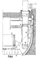
- FIG 1 we see a part of the well of tank 1 of a fast neutron nuclear reactor to the upper part of which is fixed the slab 2 closing the main tank 3 of the reactor.
- the tank 3 has a cylindrical side wall closed by a curved bottom. The upper part of the side wall suspends the tank 3 in the tank well 1.
- the main tank 3 contains sodium liquid coolant in which is immersed the core 4 of the reactor consisting of fuel assemblies whose feet are fixed in a bed base 5 resting on a platform 6 itself supported by the bottom of the tank 3.
- the main tank contains an internal tank 7 delimiting inside the main tank a hot collector filled with sodium up to level 8 in which the core 4 of the reactor is immersed and a cold collector containing liquid sodium up to the upper level 9.
- An intermediate exchanger 10 enters the tank through an opening in the slab 2 and passes through the internal tank 7 so that its upper part comprising inlet openings 11 is in the hot manifold and its lower part comprising outlet openings 12 in the cold collector.
- the device for cooling the upper part of the tank 3 generally designated by the reference 14 and visible in Figures 1 and 2 comprises a first manifold 15, a second manifold 16 and a set of cooled sodium supply tubes 17 joining the lower part of the decking 6 to the lower part of the first manifold 15.
- the first collector 15, or spill collector has an annular shape and is defined by the upper part of the wall of the main tank 3 and by a spill ring 18 connected at its lower part to the of the main tank 3 by an annular plate 19.
- the pouring shell 18 comprises a cylindrical lower part 18a connected by its lower end to the annular plate 19, an intermediate frustoconical part 18b flared upwards and a cylindrical upper part 18c terminated by a discharge threshold 20 constituted by an annular pad having a rounded section visible in FIG. 2.
- the discharge threshold 20 is continuous over the entire periphery of the shell 18c and has a shape, in meridian section, making it possible to ensure good adhesion of the blade sodium flowing over threshold 20 and avoid entrainment of the cover gas present above the level higher than sodium.
- the successive ferrules 18a, 18b and 18c constituting the discharge ferrule 18 are all coaxial with the tank 3 and have a diameter less than the diameter of this tank.
- the annular plate 19 constituting the bottom of the discharge manifold 15 is pierced with openings into which the ends of the supply tubes 17 penetrate.
- Cooled sodium from the bed base 5 into which it is injected by the reactor pumps therefore enters the overflow collector 15 which is filled up to its upper level corresponding to the overflow threshold 20.
- the second collector 16, or return collector is delimited by the upper part of the discharge ferrule 18 and by an internal ferrule 21 connected at its lower part to the discharge ferrule by an annular plate 22 welded to the discharge ferrule and at the end of the internal shell 21.
- the internal shell 21 comprises a lower part 21 a of frustoconical shape and an upper part 21 b of cylindrical shape. The upper end of the part 21 is at a level slightly above the level of the threshold 20 and has a horizontal annular rim.
- the successive ferrules 21a and 21b constituting the internal ferrule 21 are coaxial with the discharge ferrule 18 and with the wall of the main tank 3. These ferrules 21a a and 21b have diameters less than the diameter of the corresponding parts of the discharge ferrule 18.
- the internal shell 21 and the discharge shell 18 have a practically constant spacing over the entire height of the return collector 16.
- the bottom 22 of this collector is pierced with openings 23 allowing the return of the liquid sodium, with a controlled flow in the internal cold collector laughter of the main tank through the internal tank 7.
- the openings 23 are such that the level of cooled sodium which pours into the return manifold 16 is established in a position 25 located below the upper part of the threshold discharge 20.
- the height separating the upper pouring part of the threshold 20 from the level 25 of the sodium in the collector 16 is maintained at a value close to 0.32 meters.
- the height of the internal shell 21 of the return manifold 16 is substantially less than the height of the discharge shell 18.
- the upper part of this internal shell 21 being at a level close to the threshold level 20, the lower part of the shell 21 is connected to the shell 18, by the plate 22 constituting the bottom of the return manifold 16, in an area of the shell 18 remote from its ends.
- An internal ferrule or restoring ferrule 21, the height of which is close to half the height of the ferrule 18, will preferably be chosen.
- a return ferrule 21 with a height between one third and two thirds of the height of the discharge ferrule 18.
- the internal ferrule or return ferrule 21 has a vibration frequency very different from that of the discharge ferrule 18.
- the annular plate 22 constituting the bottom of the return collector 16 ensures the stiffening of the ferrule spill 18 to which it is fixed, in an area which is close to its middle part or at least, far from its ends.
- the spillway ferrule which has greater stiffness is more resistant to buckling. It is the same for the internal ferrule 21, the lower height of which is accompanied by greater stiffness.
- the two vanes delimiting the collector 16 having very different natural periods and a much higher stiffness than in the case of devices according to the prior art, the risk of vibration coupling of the two collectors is zero and the vibrations no longer tend to initiate, during the circulation of the cooling sodium shown diagrammatically by the arrows 27.
- the shape of the discharge threshold 20 makes it possible to ensure good adhesion of the sodium strip and to avoid entrainment of gas by the sodium.
- the discharge over the entire periphery of the shell 18 also easily ensures the passage of a large sodium flow.
- the arrangement according to the invention has the advantage of reducing the quantity of metal sheets used for the construction of the cooling device, the internal return ferrule 21 being of reduced height.
- the shape of the spill and return ferrules respectively may be different from that which has been described, and that the fixing of the lower part of the return ferrule to the discharge ferrule can be carried out in another way. only by means of an annular plate and that the upper part of the return ferrule can be placed at the exact level of the upper part of the discharge ferrule.
- cooling device applies to any fast neutron nuclear reactor cooled by a liquid metal.
Landscapes
- Physics & Mathematics (AREA)
- Engineering & Computer Science (AREA)
- Plasma & Fusion (AREA)
- General Engineering & Computer Science (AREA)
- High Energy & Nuclear Physics (AREA)
- Structure Of Emergency Protection For Nuclear Reactors (AREA)
- Heat-Exchange Devices With Radiators And Conduit Assemblies (AREA)
- Details Of Measuring And Other Instruments (AREA)
Claims (6)
Applications Claiming Priority (2)
| Application Number | Priority Date | Filing Date | Title |
|---|---|---|---|
| FR8614052A FR2605136B1 (fr) | 1986-10-09 | 1986-10-09 | Dispositif de refroidissement de la cuve principale d'une reacteur nucleaire a neutrons rapides refroidi par un metal liquide |
| FR8614052 | 1986-10-09 |
Publications (2)
| Publication Number | Publication Date |
|---|---|
| EP0265311A1 EP0265311A1 (de) | 1988-04-27 |
| EP0265311B1 true EP0265311B1 (de) | 1991-01-16 |
Family
ID=9339699
Family Applications (1)
| Application Number | Title | Priority Date | Filing Date |
|---|---|---|---|
| EP87402150A Expired - Lifetime EP0265311B1 (de) | 1986-10-09 | 1987-09-25 | Kühlvorrichtung des Hauptgefässes eines flüssigkeitsmetallgekühlten schnellen Neutronenreaktors |
Country Status (5)
| Country | Link |
|---|---|
| US (1) | US4927597A (de) |
| EP (1) | EP0265311B1 (de) |
| JP (1) | JPH07104428B2 (de) |
| DE (1) | DE3767430D1 (de) |
| FR (1) | FR2605136B1 (de) |
Families Citing this family (6)
| Publication number | Priority date | Publication date | Assignee | Title |
|---|---|---|---|---|
| FR2632440B1 (fr) * | 1988-06-02 | 1990-08-10 | Commissariat Energie Atomique | Reacteur nucleaire a neutrons rapides, refroidi par un metal liquide |
| FR2632760B1 (fr) * | 1988-06-09 | 1992-10-23 | Novatome | Virole interne d'un reacteur nucleaire a neutrons rapides comportant un dispositif de protection thermique |
| DE3931652A1 (de) * | 1989-09-22 | 1991-04-04 | Basf Ag | Verfahren zur herstellung von mit keramischen pulvern gefuellten thermoplastischen kunststoffen |
| JPH0593794A (ja) * | 1991-10-01 | 1993-04-16 | Toshiba Corp | ナトリウム冷却型高速炉 |
| JP2972162B2 (ja) * | 1997-04-17 | 1999-11-08 | 核燃料サイクル開発機構 | 高速炉の炉壁冷却保護構造 |
| CN113972015A (zh) * | 2021-10-22 | 2022-01-25 | 中国原子能科学研究院 | 用于快堆的辅助冷却系统及方法 |
Family Cites Families (15)
| Publication number | Priority date | Publication date | Assignee | Title |
|---|---|---|---|---|
| FR2220847B1 (de) * | 1973-03-07 | 1975-10-31 | Commissariat Energie Atomique | |
| FR2291580A1 (fr) * | 1974-11-14 | 1976-06-11 | Commissariat Energie Atomique | Dispositif de protection thermique de la cuve d'un reacteur |
| FR2333328A1 (fr) * | 1975-11-26 | 1977-06-24 | Commissariat Energie Atomique | Reacteur nucleaire |
| FR2370344A2 (fr) * | 1975-11-26 | 1978-06-02 | Commissariat Energie Atomique | Reacteur nucleaire |
| FR2425129A2 (fr) * | 1975-11-26 | 1979-11-30 | Commissariat Energie Atomique | Reacteur nucleaire |
| FR2347749A1 (fr) * | 1976-04-06 | 1977-11-04 | Commissariat Energie Atomique | Procede et dispositif de protection thermique de la cuve d'un reacteur nucleaire |
| US4298431A (en) * | 1977-06-13 | 1981-11-03 | Commissariat A L'energie Atomique | Device for the thermal protection of an internal structure of a liquid metal cooled fast reactor |
| GB2000356B (en) * | 1977-07-04 | 1982-03-10 | Commissariat Energie Atomique | A liquid-metal cooled reactor |
| BE875873R (fr) * | 1978-05-02 | 1979-08-16 | Commissariat Energie Atomique | Reacteur nucleaire |
| FR2505078A1 (fr) * | 1981-04-30 | 1982-11-05 | Novatome Ind | Dispositif de refroidissement de la cuve principale d'un reacteur nucleaire a neutrons rapides |
| FR2506062B1 (fr) * | 1981-05-13 | 1985-11-29 | Novatome | Cuve interne pour un reacteur nucleaire a neutrons rapides |
| JPS5987394A (ja) * | 1982-11-11 | 1984-05-19 | 三菱原子力工業株式会社 | 原子炉容器内オ−バフロ−構造 |
| JPS59168389A (ja) * | 1983-03-16 | 1984-09-22 | 財団法人 電力中央研究所 | 炉容器壁の断熱構造 |
| JPS59168392A (ja) * | 1983-03-16 | 1984-09-22 | 財団法人 電力中央研究所 | タンク型高速増殖炉 |
| JPS61209388A (ja) * | 1985-03-13 | 1986-09-17 | 株式会社日立製作所 | 原子炉構造 |
-
1986
- 1986-10-09 FR FR8614052A patent/FR2605136B1/fr not_active Expired - Fee Related
-
1987
- 1987-09-25 DE DE8787402150T patent/DE3767430D1/de not_active Expired - Fee Related
- 1987-09-25 EP EP87402150A patent/EP0265311B1/de not_active Expired - Lifetime
- 1987-10-08 JP JP62254509A patent/JPH07104428B2/ja not_active Expired - Lifetime
-
1989
- 1989-02-21 US US07/313,341 patent/US4927597A/en not_active Expired - Fee Related
Also Published As
| Publication number | Publication date |
|---|---|
| JPH07104428B2 (ja) | 1995-11-13 |
| JPS63115094A (ja) | 1988-05-19 |
| EP0265311A1 (de) | 1988-04-27 |
| US4927597A (en) | 1990-05-22 |
| FR2605136B1 (fr) | 1990-05-04 |
| DE3767430D1 (de) | 1991-02-21 |
| FR2605136A1 (fr) | 1988-04-15 |
Similar Documents
| Publication | Publication Date | Title |
|---|---|---|
| EP0265311B1 (de) | Kühlvorrichtung des Hauptgefässes eines flüssigkeitsmetallgekühlten schnellen Neutronenreaktors | |
| EP0344041A1 (de) | Kernreaktor mit Notkühlwassereinspeiseeinrichtung | |
| FR2646954A1 (fr) | Reacteurs nucleaires refroidis a l'eau | |
| EP0238390B1 (de) | Innere Struktur eines Kernreaktors mit länglichem Druckbehälter | |
| EP0246969A1 (de) | Kleiner Druckwasserkernreaktor mit Naturumlauf | |
| EP0057643B1 (de) | Schutzeinrichtung für die Rohrplatte an der heissen Seite eines vertikaler Wärmetauschers | |
| EP0067103B1 (de) | Schneller Brutreaktor | |
| EP0055963A2 (de) | Flüssigmetallgekühlter Kernreaktor mit einem am Boden gekühlten Behälter | |
| EP3729464B1 (de) | Strömungsberuhigungsanordnung für kernreaktor | |
| FR2541496A1 (fr) | Reacteur nucleaire a neutrons rapides a structure interne allegee | |
| EP0246143B1 (de) | Auflagervorrichtung für ein Auslassgehäuse einer in einem Kernreaktor aufgehängten Pumpe | |
| EP0024985B1 (de) | Spaltprodukte emittierende Eichvorrichtung zum Eichen einer Einrichtung zum Feststellen von Hüllenschäden in Kernreaktoren | |
| EP0018262A1 (de) | Schneller Kernreaktor mit einem zylindrischen Innenbehälter | |
| EP0048672B1 (de) | Atomkernreaktor mit Wärmetauschern in integrierter Bauweise | |
| EP0064921B1 (de) | Kühlvorrichtung des Hauptbehälters eines Kernreaktors mit schnellen Neutronen | |
| EP0258131A1 (de) | Notkühleinrichtung für schnellen Neutronenreaktor | |
| FR2555794A1 (fr) | Reacteur nucleaire a neutrons rapides equipe de moyens de refroidissement de secours | |
| EP0216667B1 (de) | Rückhaltevorrichtung für eine Flüssigkeit um zu verhindern, dass eine offene, im wesentlichen horizontale Leitung beim Unterschreiten einer bestimmten Zuflussmenge leer läuft | |
| FR2461335A1 (fr) | Dispositif de supportage du coeur dans la cuve d'un reacteur nucleaire | |
| FR2934078A1 (fr) | Reacteur nucleaire a neutrons rapides. | |
| FR2679062A1 (fr) | Cóoeur de reacteur surgenerateur rapide et assemblage combustible utilise dans un tel cóoeur. | |
| EP0092461A1 (de) | Behälter mit ringförmiger Deckelplatte für einen schnellen Kernreaktor | |
| FR2569040A1 (fr) | Structure de reacteur nucleaire surregenerateur | |
| EP0382643A1 (de) | Wärmeschutzvorrichtung eines oberen Tragringes eines hängenden Gefässes, insbesondere in einem schnellen Neutronenkernreaktor | |
| WO2013098282A1 (fr) | Circuit primaire de réacteur nucléaire, avec un piquage équipé d'une manchette thermique |
Legal Events
| Date | Code | Title | Description |
|---|---|---|---|
| PUAI | Public reference made under article 153(3) epc to a published international application that has entered the european phase |
Free format text: ORIGINAL CODE: 0009012 |
|
| AK | Designated contracting states |
Kind code of ref document: A1 Designated state(s): DE GB IT |
|
| 17P | Request for examination filed |
Effective date: 19880407 |
|
| 17Q | First examination report despatched |
Effective date: 19891012 |
|
| RAP1 | Party data changed (applicant data changed or rights of an application transferred) |
Owner name: FRAMATOME |
|
| GRAA | (expected) grant |
Free format text: ORIGINAL CODE: 0009210 |
|
| AK | Designated contracting states |
Kind code of ref document: B1 Designated state(s): DE GB IT |
|
| ITF | It: translation for a ep patent filed | ||
| REF | Corresponds to: |
Ref document number: 3767430 Country of ref document: DE Date of ref document: 19910221 |
|
| GBT | Gb: translation of ep patent filed (gb section 77(6)(a)/1977) | ||
| PGFP | Annual fee paid to national office [announced via postgrant information from national office to epo] |
Ref country code: DE Payment date: 19910822 Year of fee payment: 5 |
|
| PGFP | Annual fee paid to national office [announced via postgrant information from national office to epo] |
Ref country code: GB Payment date: 19910917 Year of fee payment: 5 |
|
| PLBE | No opposition filed within time limit |
Free format text: ORIGINAL CODE: 0009261 |
|
| STAA | Information on the status of an ep patent application or granted ep patent |
Free format text: STATUS: NO OPPOSITION FILED WITHIN TIME LIMIT |
|
| 26N | No opposition filed | ||
| PG25 | Lapsed in a contracting state [announced via postgrant information from national office to epo] |
Ref country code: GB Effective date: 19920925 |
|
| GBPC | Gb: european patent ceased through non-payment of renewal fee |
Effective date: 19920925 |
|
| PG25 | Lapsed in a contracting state [announced via postgrant information from national office to epo] |
Ref country code: DE Effective date: 19930602 |
|
| PG25 | Lapsed in a contracting state [announced via postgrant information from national office to epo] |
Ref country code: IT Free format text: LAPSE BECAUSE OF NON-PAYMENT OF DUE FEES;WARNING: LAPSES OF ITALIAN PATENTS WITH EFFECTIVE DATE BEFORE 2007 MAY HAVE OCCURRED AT ANY TIME BEFORE 2007. THE CORRECT EFFECTIVE DATE MAY BE DIFFERENT FROM THE ONE RECORDED. Effective date: 20050925 |