EP0264976A2 - A ferrule for and a method of terminating a fiber optic transmission member - Google Patents
A ferrule for and a method of terminating a fiber optic transmission member Download PDFInfo
- Publication number
- EP0264976A2 EP0264976A2 EP87201547A EP87201547A EP0264976A2 EP 0264976 A2 EP0264976 A2 EP 0264976A2 EP 87201547 A EP87201547 A EP 87201547A EP 87201547 A EP87201547 A EP 87201547A EP 0264976 A2 EP0264976 A2 EP 0264976A2
- Authority
- EP
- European Patent Office
- Prior art keywords
- fiber optic
- ferrule
- optic transmission
- transmission member
- front surface
- Prior art date
- Legal status (The legal status is an assumption and is not a legal conclusion. Google has not performed a legal analysis and makes no representation as to the accuracy of the status listed.)
- Granted
Links
- 239000000835 fiber Substances 0.000 title claims abstract description 51
- 230000005540 biological transmission Effects 0.000 title claims abstract description 42
- 238000000034 method Methods 0.000 title claims description 5
- 238000005498 polishing Methods 0.000 claims abstract description 13
- 230000002093 peripheral effect Effects 0.000 claims abstract description 4
- 239000000463 material Substances 0.000 claims description 6
- 238000000465 moulding Methods 0.000 claims description 2
- 239000011521 glass Substances 0.000 description 3
- 229910052751 metal Inorganic materials 0.000 description 3
- 239000002184 metal Substances 0.000 description 3
- 239000004033 plastic Substances 0.000 description 3
- 238000005253 cladding Methods 0.000 description 1
- 230000008878 coupling Effects 0.000 description 1
- 238000010168 coupling process Methods 0.000 description 1
- 238000005859 coupling reaction Methods 0.000 description 1
- 239000003822 epoxy resin Substances 0.000 description 1
- 239000012530 fluid Substances 0.000 description 1
- 210000003739 neck Anatomy 0.000 description 1
- TWNQGVIAIRXVLR-UHFFFAOYSA-N oxo(oxoalumanyloxy)alumane Chemical compound O=[Al]O[Al]=O TWNQGVIAIRXVLR-UHFFFAOYSA-N 0.000 description 1
- 229920000647 polyepoxide Polymers 0.000 description 1
- HBMJWWWQQXIZIP-UHFFFAOYSA-N silicon carbide Chemical compound [Si+]#[C-] HBMJWWWQQXIZIP-UHFFFAOYSA-N 0.000 description 1
- 229910010271 silicon carbide Inorganic materials 0.000 description 1
Images
Classifications
-
- G—PHYSICS
- G02—OPTICS
- G02B—OPTICAL ELEMENTS, SYSTEMS OR APPARATUS
- G02B6/00—Light guides; Structural details of arrangements comprising light guides and other optical elements, e.g. couplings
- G02B6/24—Coupling light guides
- G02B6/36—Mechanical coupling means
- G02B6/38—Mechanical coupling means having fibre to fibre mating means
- G02B6/3807—Dismountable connectors, i.e. comprising plugs
- G02B6/3833—Details of mounting fibres in ferrules; Assembly methods; Manufacture
- G02B6/3855—Details of mounting fibres in ferrules; Assembly methods; Manufacture characterised by the method of anchoring or fixing the fibre within the ferrule
- G02B6/3861—Adhesive bonding
-
- B—PERFORMING OPERATIONS; TRANSPORTING
- B24—GRINDING; POLISHING
- B24B—MACHINES, DEVICES, OR PROCESSES FOR GRINDING OR POLISHING; DRESSING OR CONDITIONING OF ABRADING SURFACES; FEEDING OF GRINDING, POLISHING, OR LAPPING AGENTS
- B24B19/00—Single-purpose machines or devices for particular grinding operations not covered by any other main group
- B24B19/22—Single-purpose machines or devices for particular grinding operations not covered by any other main group characterised by a special design with respect to properties of the material of non-metallic articles to be ground
- B24B19/226—Single-purpose machines or devices for particular grinding operations not covered by any other main group characterised by a special design with respect to properties of the material of non-metallic articles to be ground of the ends of optical fibres
-
- G—PHYSICS
- G02—OPTICS
- G02B—OPTICAL ELEMENTS, SYSTEMS OR APPARATUS
- G02B6/00—Light guides; Structural details of arrangements comprising light guides and other optical elements, e.g. couplings
- G02B6/24—Coupling light guides
- G02B6/36—Mechanical coupling means
- G02B6/38—Mechanical coupling means having fibre to fibre mating means
- G02B6/3807—Dismountable connectors, i.e. comprising plugs
- G02B6/381—Dismountable connectors, i.e. comprising plugs of the ferrule type, e.g. fibre ends embedded in ferrules, connecting a pair of fibres
- G02B6/3818—Dismountable connectors, i.e. comprising plugs of the ferrule type, e.g. fibre ends embedded in ferrules, connecting a pair of fibres of a low-reflection-loss type
- G02B6/382—Dismountable connectors, i.e. comprising plugs of the ferrule type, e.g. fibre ends embedded in ferrules, connecting a pair of fibres of a low-reflection-loss type with index-matching medium between light guides
-
- G—PHYSICS
- G02—OPTICS
- G02B—OPTICAL ELEMENTS, SYSTEMS OR APPARATUS
- G02B6/00—Light guides; Structural details of arrangements comprising light guides and other optical elements, e.g. couplings
- G02B6/24—Coupling light guides
- G02B6/36—Mechanical coupling means
- G02B6/38—Mechanical coupling means having fibre to fibre mating means
- G02B6/3807—Dismountable connectors, i.e. comprising plugs
- G02B6/381—Dismountable connectors, i.e. comprising plugs of the ferrule type, e.g. fibre ends embedded in ferrules, connecting a pair of fibres
- G02B6/3818—Dismountable connectors, i.e. comprising plugs of the ferrule type, e.g. fibre ends embedded in ferrules, connecting a pair of fibres of a low-reflection-loss type
- G02B6/3821—Dismountable connectors, i.e. comprising plugs of the ferrule type, e.g. fibre ends embedded in ferrules, connecting a pair of fibres of a low-reflection-loss type with axial spring biasing or loading means
-
- G—PHYSICS
- G02—OPTICS
- G02B—OPTICAL ELEMENTS, SYSTEMS OR APPARATUS
- G02B6/00—Light guides; Structural details of arrangements comprising light guides and other optical elements, e.g. couplings
- G02B6/24—Coupling light guides
- G02B6/36—Mechanical coupling means
- G02B6/38—Mechanical coupling means having fibre to fibre mating means
- G02B6/3807—Dismountable connectors, i.e. comprising plugs
- G02B6/381—Dismountable connectors, i.e. comprising plugs of the ferrule type, e.g. fibre ends embedded in ferrules, connecting a pair of fibres
- G02B6/3825—Dismountable connectors, i.e. comprising plugs of the ferrule type, e.g. fibre ends embedded in ferrules, connecting a pair of fibres with an intermediate part, e.g. adapter, receptacle, linking two plugs
-
- G—PHYSICS
- G02—OPTICS
- G02B—OPTICAL ELEMENTS, SYSTEMS OR APPARATUS
- G02B6/00—Light guides; Structural details of arrangements comprising light guides and other optical elements, e.g. couplings
- G02B6/24—Coupling light guides
- G02B6/36—Mechanical coupling means
- G02B6/38—Mechanical coupling means having fibre to fibre mating means
- G02B6/3807—Dismountable connectors, i.e. comprising plugs
- G02B6/3833—Details of mounting fibres in ferrules; Assembly methods; Manufacture
- G02B6/3834—Means for centering or aligning the light guide within the ferrule
-
- G—PHYSICS
- G02—OPTICS
- G02B—OPTICAL ELEMENTS, SYSTEMS OR APPARATUS
- G02B6/00—Light guides; Structural details of arrangements comprising light guides and other optical elements, e.g. couplings
- G02B6/24—Coupling light guides
- G02B6/36—Mechanical coupling means
- G02B6/38—Mechanical coupling means having fibre to fibre mating means
- G02B6/3807—Dismountable connectors, i.e. comprising plugs
- G02B6/3833—Details of mounting fibres in ferrules; Assembly methods; Manufacture
- G02B6/3865—Details of mounting fibres in ferrules; Assembly methods; Manufacture fabricated by using moulding techniques
-
- G—PHYSICS
- G02—OPTICS
- G02B—OPTICAL ELEMENTS, SYSTEMS OR APPARATUS
- G02B6/00—Light guides; Structural details of arrangements comprising light guides and other optical elements, e.g. couplings
- G02B6/24—Coupling light guides
- G02B6/36—Mechanical coupling means
- G02B6/38—Mechanical coupling means having fibre to fibre mating means
- G02B6/3807—Dismountable connectors, i.e. comprising plugs
- G02B6/389—Dismountable connectors, i.e. comprising plugs characterised by the method of fastening connecting plugs and sockets, e.g. screw- or nut-lock, snap-in, bayonet type
-
- G—PHYSICS
- G02—OPTICS
- G02B—OPTICAL ELEMENTS, SYSTEMS OR APPARATUS
- G02B6/00—Light guides; Structural details of arrangements comprising light guides and other optical elements, e.g. couplings
- G02B6/24—Coupling light guides
- G02B6/36—Mechanical coupling means
- G02B6/38—Mechanical coupling means having fibre to fibre mating means
- G02B6/3807—Dismountable connectors, i.e. comprising plugs
- G02B6/3897—Connectors fixed to housings, casing, frames or circuit boards
-
- G—PHYSICS
- G02—OPTICS
- G02B—OPTICAL ELEMENTS, SYSTEMS OR APPARATUS
- G02B6/00—Light guides; Structural details of arrangements comprising light guides and other optical elements, e.g. couplings
- G02B6/24—Coupling light guides
- G02B6/36—Mechanical coupling means
- G02B6/38—Mechanical coupling means having fibre to fibre mating means
- G02B6/3807—Dismountable connectors, i.e. comprising plugs
- G02B6/3833—Details of mounting fibres in ferrules; Assembly methods; Manufacture
- G02B6/3854—Ferrules characterised by materials
-
- G—PHYSICS
- G02—OPTICS
- G02B—OPTICAL ELEMENTS, SYSTEMS OR APPARATUS
- G02B6/00—Light guides; Structural details of arrangements comprising light guides and other optical elements, e.g. couplings
- G02B6/24—Coupling light guides
- G02B6/36—Mechanical coupling means
- G02B6/38—Mechanical coupling means having fibre to fibre mating means
- G02B6/3807—Dismountable connectors, i.e. comprising plugs
- G02B6/3833—Details of mounting fibres in ferrules; Assembly methods; Manufacture
- G02B6/3863—Details of mounting fibres in ferrules; Assembly methods; Manufacture fabricated by using polishing techniques
-
- G—PHYSICS
- G02—OPTICS
- G02B—OPTICAL ELEMENTS, SYSTEMS OR APPARATUS
- G02B6/00—Light guides; Structural details of arrangements comprising light guides and other optical elements, e.g. couplings
- G02B6/24—Coupling light guides
- G02B6/36—Mechanical coupling means
- G02B6/38—Mechanical coupling means having fibre to fibre mating means
- G02B6/3807—Dismountable connectors, i.e. comprising plugs
- G02B6/3833—Details of mounting fibres in ferrules; Assembly methods; Manufacture
- G02B6/3867—Details of mounting fibres in ferrules; Assembly methods; Manufacture comprising air venting holes
-
- G—PHYSICS
- G02—OPTICS
- G02B—OPTICAL ELEMENTS, SYSTEMS OR APPARATUS
- G02B6/00—Light guides; Structural details of arrangements comprising light guides and other optical elements, e.g. couplings
- G02B6/24—Coupling light guides
- G02B6/36—Mechanical coupling means
- G02B6/38—Mechanical coupling means having fibre to fibre mating means
- G02B6/3807—Dismountable connectors, i.e. comprising plugs
- G02B6/3898—Tools, e.g. handheld; Tuning wrenches; Jigs used with connectors, e.g. for extracting, removing or inserting in a panel, for engaging or coupling connectors, for assembling or disassembling components within the connector, for applying clips to hold two connectors together or for crimping
Definitions
- This invention relates to a ferrule for and a method of terminating a fiber optic transmission member.
- US Patent No. 3 999 837 discloses a fiber optic connector which comprises a housing member and ferrule members terminated onto exposed ends of fiber optic transmission members.
- the housing member has a profiled bore including a center cylindrical section and outer first and second identically-shaped sections of different diameters.
- the ferrule members have cylindrical nose section that tightly fit into the cylindrical section of the housing, tapered sections that engage the outer first and second sections, and annular shoulders that engage surfaces of the housing member.
- Coupling members on the ferrule members are coupled to the housing member securing the ferrule members in the profiled bore with the cylindrical section applying radial compressive forces to the cylindrical nose sections thereby axially aligning the fiber optic transmission members and the annular shoulders engage the surfaces of the housing member limiting movement of the ferrule members into the profiled bore, positioning the front surfaces of the ferrule members adjacent each other and minimizing misalignment of the fiber optic transmission members when lateral forces are applied to the ferrule members.
- a ferrule member according to the invention is characterised in that a front end on said ferrule member has a domed front surface prior to the fiber optic transmission member being terminated in said ferrule member and the domed front surface along with an end of said fiber optic transmission member being polished thereby forming a planar front surface of said front end of said ferrule member and said fiber optic transmission member.
- a method of terminating an end of a fiber optic transmission member within a ferrule member comprises the steps of molding the ferrule member from a suitable material with a front end of the ferrule member having a domed front surface and a bore extending through the ferrule member and through the domed front surface; securing the end of the fiber optic transmission member in the bore with a front end of the fiber optic transmission member being coincident with the domed front surface; and polishing the domed front surface and the front end of the fiber optic transmission member thereby forming a flat polished surface of the front end of the ferrule member including a flat polished surface of the front end of the fiber optic transmission member.
- a ferrule member 10 is terminated onto an end of a fiber optic cable 12.
- the fiber optic cable 12 includes a fiber optic tranmission member 14 surrounded by cladding material to enable light to be transmitted ther ealong.
- Buffer material 16 as shown in Figure 8, protects the cladded fiber optic transmission member 14 and an outer jacket 18 protects the entire cable assembly.
- the cable typically includes strength members (not shown) to provide tensile strength thereto.
- Fiber optic cable 12 is stripped to expose a length of fiber optic transmission member 14 to enable it to be terminated in ferrule member 10.
- Fiber optic transmission member 14 can be either plastic or glass.
- Ferrule member 10 is preferably molded from a suitable plastic material having resilient characteristics.
- Ferrule member 10 is of the type disclosed in US Patent No. 3 999 837, the disclosure of which is completely incorporated herein by reference.
- Ferrule member 10 has a profiled front end which comprises a front surface 34, a front cylindrical section 20, a tapered section 22, an intermediate cylindrical alignment section 24, a rear cylindrical section 26, and a tubular section 28 (see Figure 8).
- a shoulder 30 is located at the junction of sections 24 and 26.
- a profiled bore 32 extends through ferrule member 10 and necks down in front cylindrical section 20 to a diameter to accommodate fiber optic transmission member 14.
- Front surface 34 of ferrule member 10 has a domed configuration when formed, as best illustrated in Figure 3.
- a metal ferrule 36 is disposed on tubular section 28 and has a flange 38 in engagement with section 26.
- Outer end 40 of metal ferrule 36 has a hexagonal or other suitable configuration.
- Fiber optic cable 12 is terminated in ferrule member 10 by inserting a stripped end of fiber optic cable 12 within bore 32 until a short section of fiber optic transmission member 14 extends outwardly beyond domed front end 34.
- An epoxy resin can be located in bore 32 to secure fiber optic transmission member 14 in position in ferrule member 10, whereafter metal ferrule 36 is crimped onto outer jacket 18 of fiber optic cable 12 thereby terminating fiber optic cable 12 in ferrule member 10.
- the section of fiber optic transmission member 14 that extends beyond domed front end 34 is removed by cutting, if transmission member 14 is plastic, or is cleaved, if transmission member 14 is glass.
- Fiber optic cable 12 can be secured in ferrule member 10 in accordance with the teachings of European Patent Application No. 83302655.2 filed 10 May 1983 or in any other suitable manner.
- the profiled front end of ferrule member 10 is frictionally positioned in a profiled bore 44 of polishing fixture 42; bore 44 has the same configuration as that of sections 20, 22 and 24 of ferrule member 10 except that they are dimensioned to compress section 20 in tight engagement with the fiber optic transmission member 14 in bore 32 and the domed front end 34 extends beyond the outer flat surface 46 of fixture 42. Radiussed projections 48 extend outwardly from surface 46.
- Terminated ferrule member 10 with fixture 42 thereon is now subjected to a polishing action by fixture 42 moving relative to a polishing medium 50 such as, for example, very fine silicon carbide or aluminum oxide grit, as shown in Figure 2, for a period of time.
- a polishing medium 50 such as, for example, very fine silicon carbide or aluminum oxide grit, as shown in Figure 2, for a period of time.
- Radiussed projections 48 stabilize the polishing and, when they are worn away, the domed front surface 34 along with the end of fiber optic transmission member 14 are polished as a flat surface 35 and are in the same plane, as illustrated in Figure 4, leaving a radiussed peripheral surface 52 between the front polished surface 35 and the external surface of cylindrical section 20.
- the radiussed peripheral surface 52 of a ferrule 10 enables a reservoir space to be formed within a connector for accommodating index expansion fluid as more fully disclosed in EP-A-0 128 044 from which this application is divided.
Abstract
Description
- This invention relates to a ferrule for and a method of terminating a fiber optic transmission member.
- US Patent No. 3 999 837 discloses a fiber optic connector which comprises a housing member and ferrule members terminated onto exposed ends of fiber optic transmission members. The housing member has a profiled bore including a center cylindrical section and outer first and second identically-shaped sections of different diameters. The ferrule members have cylindrical nose section that tightly fit into the cylindrical section of the housing, tapered sections that engage the outer first and second sections, and annular shoulders that engage surfaces of the housing member. Coupling members on the ferrule members are coupled to the housing member securing the ferrule members in the profiled bore with the cylindrical section applying radial compressive forces to the cylindrical nose sections thereby axially aligning the fiber optic transmission members and the annular shoulders engage the surfaces of the housing member limiting movement of the ferrule members into the profiled bore, positioning the front surfaces of the ferrule members adjacent each other and minimizing misalignment of the fiber optic transmission members when lateral forces are applied to the ferrule members.
- It is an object to provide an improved ferrule member to facilitate polishing of a fiber optic transmission member terminated therein.
- A ferrule member according to the invention is characterised in that a front end on said ferrule member has a domed front surface prior to the fiber optic transmission member being terminated in said ferrule member and the domed front surface along with an end of said fiber optic transmission member being polished thereby forming a planar front surface of said front end of said ferrule member and said fiber optic transmission member.
- A method of terminating an end of a fiber optic transmission member within a ferrule member, according to the invention, comprises the steps of molding the ferrule member from a suitable material with a front end of the ferrule member having a domed front surface and a bore extending through the ferrule member and through the domed front surface; securing the end of the fiber optic transmission member in the bore with a front end of the fiber optic transmission member being coincident with the domed front surface; and polishing the domed front surface and the front end of the fiber optic transmission member thereby forming a flat polished surface of the front end of the ferrule member including a flat polished surface of the front end of the fiber optic transmission member.
- The invention will now be described, by way of example, with reference to the accompanying partly diagrammatic drawings, in which:-
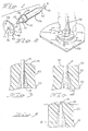
- Figure 1 is a perspective view of a ferrule member terminated to a fiber optic transmission member and a polishing fixture exploded therefrom,
- Figure 2 is a perspective view showing the polishing of the front end of the ferrule member and fiber optic transmission member,
- Figure 3 is a cross-sectional view of the front end of the ferrule member terminated onto a fiber optic transmission member prior to polishing.
- Figure 4 is a view similar to Figure 3 after the front end of the ferrule member and fiber optic transmission member have been polished, and
- Figure 5 is a view similar to Figure 3 showing a cleaved end of a fiber optic transmission member prior to polishing the front end of the terminated ferrule member.
- A
ferrule member 10 is terminated onto an end of a fiberoptic cable 12. The fiberoptic cable 12 includes a fiberoptic tranmission member 14 surrounded by cladding material to enable light to be transmitted ther ealong. Buffer material 16, as shown in Figure 8, protects the cladded fiberoptic transmission member 14 and anouter jacket 18 protects the entire cable assembly. The cable typically includes strength members (not shown) to provide tensile strength thereto. Fiberoptic cable 12 is stripped to expose a length of fiberoptic transmission member 14 to enable it to be terminated inferrule member 10. Fiberoptic transmission member 14 can be either plastic or glass. - Ferrule
member 10 is preferably molded from a suitable plastic material having resilient characteristics. Ferrulemember 10 is of the type disclosed in US Patent No. 3 999 837, the disclosure of which is completely incorporated herein by reference. Ferrulemember 10 has a profiled front end which comprises afront surface 34, a frontcylindrical section 20, atapered section 22, an intermediatecylindrical alignment section 24, a rearcylindrical section 26, and a tubular section 28 (see Figure 8). A shoulder 30 is located at the junction ofsections profiled bore 32 extends throughferrule member 10 and necks down in frontcylindrical section 20 to a diameter to accommodate fiberoptic transmission member 14.Front surface 34 offerrule member 10 has a domed configuration when formed, as best illustrated in Figure 3. Ametal ferrule 36 is disposed on tubular section 28 and has aflange 38 in engagement withsection 26.Outer end 40 ofmetal ferrule 36 has a hexagonal or other suitable configuration. - Fiber
optic cable 12 is terminated inferrule member 10 by inserting a stripped end of fiberoptic cable 12 withinbore 32 until a short section of fiberoptic transmission member 14 extends outwardly beyonddomed front end 34. An epoxy resin can be located inbore 32 to secure fiberoptic transmission member 14 in position inferrule member 10, whereaftermetal ferrule 36 is crimped ontoouter jacket 18 of fiberoptic cable 12 thereby terminating fiberoptic cable 12 inferrule member 10. The section of fiberoptic transmission member 14 that extends beyonddomed front end 34 is removed by cutting, iftransmission member 14 is plastic, or is cleaved, iftransmission member 14 is glass. Fiberoptic cable 12 can be secured inferrule member 10 in accordance with the teachings of European Patent Application No. 83302655.2 filed 10 May 1983 or in any other suitable manner. - After the fiber
optic cable 12 has been terminated inferrule member 10, the profiled front end offerrule member 10 is frictionally positioned in aprofiled bore 44 ofpolishing fixture 42;bore 44 has the same configuration as that ofsections ferrule member 10 except that they are dimensioned to compresssection 20 in tight engagement with the fiberoptic transmission member 14 inbore 32 and thedomed front end 34 extends beyond the outerflat surface 46 offixture 42.Radiussed projections 48 extend outwardly fromsurface 46. - Terminated
ferrule member 10 withfixture 42 thereon is now subjected to a polishing action byfixture 42 moving relative to apolishing medium 50 such as, for example, very fine silicon carbide or aluminum oxide grit, as shown in Figure 2, for a period of time.Radiussed projections 48 stabilize the polishing and, when they are worn away, thedomed front surface 34 along with the end of fiberoptic transmission member 14 are polished as aflat surface 35 and are in the same plane, as illustrated in Figure 4, leaving a radiussedperipheral surface 52 between the front polishedsurface 35 and the external surface ofcylindrical section 20. - As shown in Figure 5, when fiber optic transmission member is glass and is cleaved, the cleaved end can be uneven. Thus, when the
domed front end 34 is polished as hereinabove described, the uneven end of fiberoptic transmission member 14 is polished to a flat planar configuration, as shown in Figure 4, thereby eliminating the fragmented end. - Advantages of having a
domed front surface 34 are less mat erial to polish and this reduces the amount of time to polish the front end offerrule member 10. - The radiussed
peripheral surface 52 of aferrule 10 enables a reservoir space to be formed within a connector for accommodating index expansion fluid as more fully disclosed in EP-A-0 128 044 from which this application is divided.
Claims (3)
molding the ferrule member (10) from a suitable material with a front end of the ferrule member (10) having a domed front surface (34) and a bore (56) extending through the ferrule member (10) and through the domed front surface (34);
securing the end of the fiber optic transmission member (14) in the bore (56) with a front end of the fiber optic transmission member (14) being coincident with the domed front surface (34); and
polishing the domed front surface (34) and the front end of the fiber optic transmission member (14) thereby forming a flat polished surface (35) of the front end of the ferrule member (10) including a flat polished surface of the front end of the fiber optic transmission member (14).
Applications Claiming Priority (4)
| Application Number | Priority Date | Filing Date | Title |
|---|---|---|---|
| US50159983A | 1983-06-06 | 1983-06-06 | |
| US50159783A | 1983-06-06 | 1983-06-06 | |
| US501599 | 1983-06-06 | ||
| US501597 | 1983-06-06 |
Related Parent Applications (1)
| Application Number | Title | Priority Date | Filing Date |
|---|---|---|---|
| EP84303789.6 Division | 1984-06-05 |
Publications (3)
| Publication Number | Publication Date |
|---|---|
| EP0264976A2 true EP0264976A2 (en) | 1988-04-27 |
| EP0264976A3 EP0264976A3 (en) | 1988-05-11 |
| EP0264976B1 EP0264976B1 (en) | 1991-03-20 |
Family
ID=27053872
Family Applications (2)
| Application Number | Title | Priority Date | Filing Date |
|---|---|---|---|
| EP87201547A Expired EP0264976B1 (en) | 1983-06-06 | 1984-06-05 | A ferrule for and a method of terminating a fiber optic transmission member |
| EP84303789A Expired EP0128044B1 (en) | 1983-06-06 | 1984-06-05 | Fiber optic connector having dual supporting surfaces and method of terminating fiber optic transmission members |
Family Applications After (1)
| Application Number | Title | Priority Date | Filing Date |
|---|---|---|---|
| EP84303789A Expired EP0128044B1 (en) | 1983-06-06 | 1984-06-05 | Fiber optic connector having dual supporting surfaces and method of terminating fiber optic transmission members |
Country Status (6)
| Country | Link |
|---|---|
| EP (2) | EP0264976B1 (en) |
| JP (2) | JPH02197807A (en) |
| CA (1) | CA1244691A (en) |
| DE (2) | DE3479761D1 (en) |
| HK (1) | HK56694A (en) |
| SG (1) | SG69192G (en) |
Cited By (2)
| Publication number | Priority date | Publication date | Assignee | Title |
|---|---|---|---|---|
| GB2246875A (en) * | 1990-06-05 | 1992-02-12 | Seiko Instr Inc | Making an optic fibre-termination |
| FR2686426A1 (en) * | 1992-01-21 | 1993-07-23 | Methode Electonics Inc | PLASTIC MOLDED BOLT FOR AN OPTICAL FIBER CONNECTOR AND METHODS OF MANUFACTURING SUCH A CONNECTOR AND SUCH A VIROLE. |
Families Citing this family (7)
| Publication number | Priority date | Publication date | Assignee | Title |
|---|---|---|---|---|
| US4759600A (en) * | 1985-05-15 | 1988-07-26 | Amp Incorporated | Holder for fiber optic connectors |
| GB2233782B (en) * | 1989-07-14 | 1993-07-07 | Stc Plc | Optical fibre cable joint |
| US5533157A (en) * | 1992-11-02 | 1996-07-02 | Itt Corporation | Optical fiber connector biasing arrangement |
| DE69233428D1 (en) * | 1992-11-02 | 2004-11-11 | Itt Mfg Enterprises Inc | TENSIONING DEVICE FOR FIBER OPTICAL CONNECTORS |
| JP3927054B2 (en) * | 2002-03-14 | 2007-06-06 | 株式会社精工技研 | Optical fiber end face polishing method and ferrule used therefor |
| JP6278627B2 (en) * | 2013-07-18 | 2018-02-14 | 富士通コンポーネント株式会社 | Optical module |
| CN109425940A (en) * | 2017-09-01 | 2019-03-05 | 中航光电科技股份有限公司 | A kind of fiber optic connector assembly and its optical fiber connector, contact |
Citations (4)
| Publication number | Priority date | Publication date | Assignee | Title |
|---|---|---|---|---|
| DE2516858A1 (en) * | 1975-04-17 | 1976-10-28 | Siemens Ag | Releasable connector for fibre optic cables - is simple and robust with no microscopic guide elements |
| US4303304A (en) * | 1979-11-30 | 1981-12-01 | Amp Incorporated | Universal optical waveguide alignment ferrule |
| US4362356A (en) * | 1978-09-11 | 1982-12-07 | Amp Incorporated | Concentric optic termination utilizing a fixture |
| EP0097576A1 (en) * | 1982-06-22 | 1984-01-04 | Socapex | Ferrule for centering an optical fibre |
Family Cites Families (5)
| Publication number | Priority date | Publication date | Assignee | Title |
|---|---|---|---|---|
| US3999837A (en) * | 1975-01-03 | 1976-12-28 | Amp Incorporated | Light transmitting fiber bundle connector |
| JPS5522707A (en) * | 1978-08-04 | 1980-02-18 | Nippon Telegr & Teleph Corp <Ntt> | Plug for optical fiber |
| US4292260A (en) * | 1980-09-22 | 1981-09-29 | Bell Telephone Laboratories, Incorporated | Molding optical fiber connectors |
| DE3138290A1 (en) * | 1981-09-25 | 1983-04-07 | Bunker Ramo Corp., 60521 Oak Brook, Ill. | BRACKET ELEMENT, ESPECIALLY GUIDE BODY FOR A LIGHTWAVE GUIDE |
| US4447121A (en) * | 1981-11-06 | 1984-05-08 | Amp Incorporated | Connector for fiber optic member |
-
1984
- 1984-06-04 CA CA000455821A patent/CA1244691A/en not_active Expired
- 1984-06-05 EP EP87201547A patent/EP0264976B1/en not_active Expired
- 1984-06-05 DE DE8484303789T patent/DE3479761D1/en not_active Expired
- 1984-06-05 DE DE8787201547T patent/DE3484316D1/en not_active Expired - Fee Related
- 1984-06-05 EP EP84303789A patent/EP0128044B1/en not_active Expired
-
1989
- 1989-09-11 JP JP1235501A patent/JPH02197807A/en active Pending
-
1991
- 1991-11-13 JP JP3325273A patent/JPH0729261B2/en not_active Expired - Lifetime
-
1992
- 1992-07-03 SG SG691/92A patent/SG69192G/en unknown
-
1994
- 1994-05-24 HK HK56694A patent/HK56694A/en not_active IP Right Cessation
Patent Citations (4)
| Publication number | Priority date | Publication date | Assignee | Title |
|---|---|---|---|---|
| DE2516858A1 (en) * | 1975-04-17 | 1976-10-28 | Siemens Ag | Releasable connector for fibre optic cables - is simple and robust with no microscopic guide elements |
| US4362356A (en) * | 1978-09-11 | 1982-12-07 | Amp Incorporated | Concentric optic termination utilizing a fixture |
| US4303304A (en) * | 1979-11-30 | 1981-12-01 | Amp Incorporated | Universal optical waveguide alignment ferrule |
| EP0097576A1 (en) * | 1982-06-22 | 1984-01-04 | Socapex | Ferrule for centering an optical fibre |
Cited By (4)
| Publication number | Priority date | Publication date | Assignee | Title |
|---|---|---|---|---|
| GB2246875A (en) * | 1990-06-05 | 1992-02-12 | Seiko Instr Inc | Making an optic fibre-termination |
| GB2246875B (en) * | 1990-06-05 | 1994-07-13 | Seiko Instr Inc | Method of making an optical fibre termination |
| US5464361A (en) * | 1990-06-05 | 1995-11-07 | Seiko Instruments Inc. | Method of making fiber termination |
| FR2686426A1 (en) * | 1992-01-21 | 1993-07-23 | Methode Electonics Inc | PLASTIC MOLDED BOLT FOR AN OPTICAL FIBER CONNECTOR AND METHODS OF MANUFACTURING SUCH A CONNECTOR AND SUCH A VIROLE. |
Also Published As
| Publication number | Publication date |
|---|---|
| HK56694A (en) | 1994-06-03 |
| DE3479761D1 (en) | 1989-10-19 |
| CA1244691A (en) | 1988-11-15 |
| EP0264976B1 (en) | 1991-03-20 |
| JPH02197807A (en) | 1990-08-06 |
| EP0128044B1 (en) | 1989-09-13 |
| SG69192G (en) | 1992-09-04 |
| EP0128044A2 (en) | 1984-12-12 |
| EP0128044A3 (en) | 1986-02-12 |
| EP0264976A3 (en) | 1988-05-11 |
| JPH0511142A (en) | 1993-01-19 |
| DE3484316D1 (en) | 1991-04-25 |
| JPH0729261B2 (en) | 1995-04-05 |
Similar Documents
| Publication | Publication Date | Title |
|---|---|---|
| US4741590A (en) | Fiber optic connector | |
| EP0514722B1 (en) | Multifiber optical connector plug with low reflection and low insertion loss | |
| US4303304A (en) | Universal optical waveguide alignment ferrule | |
| CA1321911C (en) | Fiber optic connector element and method for its use | |
| US4666241A (en) | Fiber optic connector and method for terminating fiber optic transmission members | |
| EP0088410B1 (en) | Optical fiber connectors | |
| US4648688A (en) | Connector for fiber optic member including polishing fixture and method of terminating same | |
| JP3515677B2 (en) | Optical connector and its mounting method | |
| US4773725A (en) | Termination of a fiber optic transmission member and method therefore | |
| US5142602A (en) | Fiber optic connectors | |
| US4588256A (en) | Optical fiber connector | |
| US4725117A (en) | Optical fiber contact and method of terminating an optical fiber using same | |
| EP0635740B1 (en) | Field installable optical fiber connectors | |
| US4614402A (en) | Fiber optic connector and method of terminating fiber optic transmission members | |
| US4787701A (en) | Optical fiber contact assembly | |
| US4812008A (en) | Method and apparatus for connecting optical fibers | |
| US6648521B2 (en) | Single terminus connector with preterminated fiber and fiber guide tube | |
| US4930859A (en) | Fiber optic splice assembly | |
| EP0301775B1 (en) | Method and apparatus for terminating an optical fiber | |
| EP0264976A2 (en) | A ferrule for and a method of terminating a fiber optic transmission member | |
| US4383732A (en) | Fiber optic connector | |
| EP0095281B1 (en) | Connector for fiber optic member | |
| US5799122A (en) | Multifiber optical connector | |
| EP0182577A2 (en) | Optical fiber contact | |
| EP0058344B1 (en) | Method of terminating an optical fiber |
Legal Events
| Date | Code | Title | Description |
|---|---|---|---|
| PUAI | Public reference made under article 153(3) epc to a published international application that has entered the european phase |
Free format text: ORIGINAL CODE: 0009012 |
|
| PUAL | Search report despatched |
Free format text: ORIGINAL CODE: 0009013 |
|
| 17P | Request for examination filed |
Effective date: 19870903 |
|
| AC | Divisional application: reference to earlier application |
Ref document number: 128044 Country of ref document: EP |
|
| AK | Designated contracting states |
Kind code of ref document: A2 Designated state(s): AT BE CH DE FR GB IT LI NL SE |
|
| AK | Designated contracting states |
Kind code of ref document: A3 Designated state(s): AT BE CH DE FR GB IT LI NL SE |
|
| 17Q | First examination report despatched |
Effective date: 19891018 |
|
| RAP1 | Party data changed (applicant data changed or rights of an application transferred) |
Owner name: AMP INCORPORATED |
|
| RBV | Designated contracting states (corrected) |
Designated state(s): DE FR NL |
|
| GRAA | (expected) grant |
Free format text: ORIGINAL CODE: 0009210 |
|
| AC | Divisional application: reference to earlier application |
Ref document number: 128044 Country of ref document: EP |
|
| AK | Designated contracting states |
Kind code of ref document: B1 Designated state(s): DE FR NL |
|
| REF | Corresponds to: |
Ref document number: 3484316 Country of ref document: DE Date of ref document: 19910425 |
|
| ET | Fr: translation filed | ||
| PLBE | No opposition filed within time limit |
Free format text: ORIGINAL CODE: 0009261 |
|
| STAA | Information on the status of an ep patent application or granted ep patent |
Free format text: STATUS: NO OPPOSITION FILED WITHIN TIME LIMIT |
|
| 26N | No opposition filed | ||
| PGFP | Annual fee paid to national office [announced via postgrant information from national office to epo] |
Ref country code: NL Payment date: 19990322 Year of fee payment: 16 |
|
| PGFP | Annual fee paid to national office [announced via postgrant information from national office to epo] |
Ref country code: FR Payment date: 19990602 Year of fee payment: 16 |
|
| PGFP | Annual fee paid to national office [announced via postgrant information from national office to epo] |
Ref country code: DE Payment date: 19990624 Year of fee payment: 16 |
|
| PG25 | Lapsed in a contracting state [announced via postgrant information from national office to epo] |
Ref country code: NL Free format text: LAPSE BECAUSE OF NON-PAYMENT OF DUE FEES Effective date: 20010101 |
|
| PG25 | Lapsed in a contracting state [announced via postgrant information from national office to epo] |
Ref country code: FR Free format text: LAPSE BECAUSE OF NON-PAYMENT OF DUE FEES Effective date: 20010228 |
|
| NLV4 | Nl: lapsed or anulled due to non-payment of the annual fee |
Effective date: 20010101 |
|
| REG | Reference to a national code |
Ref country code: FR Ref legal event code: ST |
|
| PG25 | Lapsed in a contracting state [announced via postgrant information from national office to epo] |
Ref country code: DE Free format text: LAPSE BECAUSE OF NON-PAYMENT OF DUE FEES Effective date: 20010403 |