EP0264968B1 - Electrostatic copying apparatus - Google Patents
Electrostatic copying apparatus Download PDFInfo
- Publication number
- EP0264968B1 EP0264968B1 EP19870115898 EP87115898A EP0264968B1 EP 0264968 B1 EP0264968 B1 EP 0264968B1 EP 19870115898 EP19870115898 EP 19870115898 EP 87115898 A EP87115898 A EP 87115898A EP 0264968 B1 EP0264968 B1 EP 0264968B1
- Authority
- EP
- European Patent Office
- Prior art keywords
- sheet material
- guide
- fixing
- roller pair
- guide member
- Prior art date
- Legal status (The legal status is an assumption and is not a legal conclusion. Google has not performed a legal analysis and makes no representation as to the accuracy of the status listed.)
- Expired - Lifetime
Links
Images


Classifications
-
- G—PHYSICS
- G03—PHOTOGRAPHY; CINEMATOGRAPHY; ANALOGOUS TECHNIQUES USING WAVES OTHER THAN OPTICAL WAVES; ELECTROGRAPHY; HOLOGRAPHY
- G03G—ELECTROGRAPHY; ELECTROPHOTOGRAPHY; MAGNETOGRAPHY
- G03G21/00—Arrangements not provided for by groups G03G13/00 - G03G19/00, e.g. cleaning, elimination of residual charge
- G03G21/16—Mechanical means for facilitating the maintenance of the apparatus, e.g. modular arrangements
- G03G21/1604—Arrangement or disposition of the entire apparatus
- G03G21/1623—Means to access the interior of the apparatus
- G03G21/1628—Clamshell type
-
- G—PHYSICS
- G03—PHOTOGRAPHY; CINEMATOGRAPHY; ANALOGOUS TECHNIQUES USING WAVES OTHER THAN OPTICAL WAVES; ELECTROGRAPHY; HOLOGRAPHY
- G03B—APPARATUS OR ARRANGEMENTS FOR TAKING PHOTOGRAPHS OR FOR PROJECTING OR VIEWING THEM; APPARATUS OR ARRANGEMENTS EMPLOYING ANALOGOUS TECHNIQUES USING WAVES OTHER THAN OPTICAL WAVES; ACCESSORIES THEREFOR
- G03B27/00—Photographic printing apparatus
- G03B27/32—Projection printing apparatus, e.g. enlarger, copying camera
- G03B27/52—Details
- G03B27/62—Holders for the original
- G03B27/6207—Holders for the original in copying cameras
- G03B27/6221—Transparent copy platens
- G03B27/6235—Reciprocating copy platens
-
- G—PHYSICS
- G03—PHOTOGRAPHY; CINEMATOGRAPHY; ANALOGOUS TECHNIQUES USING WAVES OTHER THAN OPTICAL WAVES; ELECTROGRAPHY; HOLOGRAPHY
- G03G—ELECTROGRAPHY; ELECTROPHOTOGRAPHY; MAGNETOGRAPHY
- G03G15/00—Apparatus for electrographic processes using a charge pattern
- G03G15/06—Apparatus for electrographic processes using a charge pattern for developing
- G03G15/08—Apparatus for electrographic processes using a charge pattern for developing using a solid developer, e.g. powder developer
- G03G15/09—Apparatus for electrographic processes using a charge pattern for developing using a solid developer, e.g. powder developer using magnetic brush
- G03G15/0921—Details concerning the magnetic brush roller structure, e.g. magnet configuration
-
- G—PHYSICS
- G03—PHOTOGRAPHY; CINEMATOGRAPHY; ANALOGOUS TECHNIQUES USING WAVES OTHER THAN OPTICAL WAVES; ELECTROGRAPHY; HOLOGRAPHY
- G03G—ELECTROGRAPHY; ELECTROPHOTOGRAPHY; MAGNETOGRAPHY
- G03G15/00—Apparatus for electrographic processes using a charge pattern
- G03G15/20—Apparatus for electrographic processes using a charge pattern for fixing, e.g. by using heat
- G03G15/2003—Apparatus for electrographic processes using a charge pattern for fixing, e.g. by using heat using heat
- G03G15/2014—Apparatus for electrographic processes using a charge pattern for fixing, e.g. by using heat using heat using contact heat
- G03G15/2017—Structural details of the fixing unit in general, e.g. cooling means, heat shielding means
- G03G15/2028—Structural details of the fixing unit in general, e.g. cooling means, heat shielding means with means for handling the copy material in the fixing nip, e.g. introduction guides, stripping means
-
- G—PHYSICS
- G03—PHOTOGRAPHY; CINEMATOGRAPHY; ANALOGOUS TECHNIQUES USING WAVES OTHER THAN OPTICAL WAVES; ELECTROGRAPHY; HOLOGRAPHY
- G03G—ELECTROGRAPHY; ELECTROPHOTOGRAPHY; MAGNETOGRAPHY
- G03G15/00—Apparatus for electrographic processes using a charge pattern
- G03G15/20—Apparatus for electrographic processes using a charge pattern for fixing, e.g. by using heat
- G03G15/2003—Apparatus for electrographic processes using a charge pattern for fixing, e.g. by using heat using heat
- G03G15/2014—Apparatus for electrographic processes using a charge pattern for fixing, e.g. by using heat using heat using contact heat
- G03G15/2039—Apparatus for electrographic processes using a charge pattern for fixing, e.g. by using heat using heat using contact heat with means for controlling the fixing temperature
-
- G—PHYSICS
- G03—PHOTOGRAPHY; CINEMATOGRAPHY; ANALOGOUS TECHNIQUES USING WAVES OTHER THAN OPTICAL WAVES; ELECTROGRAPHY; HOLOGRAPHY
- G03G—ELECTROGRAPHY; ELECTROPHOTOGRAPHY; MAGNETOGRAPHY
- G03G15/00—Apparatus for electrographic processes using a charge pattern
- G03G15/65—Apparatus which relate to the handling of copy material
- G03G15/6588—Apparatus which relate to the handling of copy material characterised by the copy material, e.g. postcards, large copies, multi-layered materials, coloured sheet material
- G03G15/6594—Apparatus which relate to the handling of copy material characterised by the copy material, e.g. postcards, large copies, multi-layered materials, coloured sheet material characterised by the format or the thickness, e.g. endless forms
-
- G—PHYSICS
- G03—PHOTOGRAPHY; CINEMATOGRAPHY; ANALOGOUS TECHNIQUES USING WAVES OTHER THAN OPTICAL WAVES; ELECTROGRAPHY; HOLOGRAPHY
- G03G—ELECTROGRAPHY; ELECTROPHOTOGRAPHY; MAGNETOGRAPHY
- G03G2215/00—Apparatus for electrophotographic processes
- G03G2215/00362—Apparatus for electrophotographic processes relating to the copy medium handling
- G03G2215/00367—The feeding path segment where particular handling of the copy medium occurs, segments being adjacent and non-overlapping. Each segment is identified by the most downstream point in the segment, so that for instance the segment labelled "Fixing device" is referring to the path between the "Transfer device" and the "Fixing device"
- G03G2215/00371—General use over the entire feeding path
-
- G—PHYSICS
- G03—PHOTOGRAPHY; CINEMATOGRAPHY; ANALOGOUS TECHNIQUES USING WAVES OTHER THAN OPTICAL WAVES; ELECTROGRAPHY; HOLOGRAPHY
- G03G—ELECTROGRAPHY; ELECTROPHOTOGRAPHY; MAGNETOGRAPHY
- G03G2215/00—Apparatus for electrophotographic processes
- G03G2215/00362—Apparatus for electrophotographic processes relating to the copy medium handling
- G03G2215/00367—The feeding path segment where particular handling of the copy medium occurs, segments being adjacent and non-overlapping. Each segment is identified by the most downstream point in the segment, so that for instance the segment labelled "Fixing device" is referring to the path between the "Transfer device" and the "Fixing device"
- G03G2215/00413—Fixing device
-
- G—PHYSICS
- G03—PHOTOGRAPHY; CINEMATOGRAPHY; ANALOGOUS TECHNIQUES USING WAVES OTHER THAN OPTICAL WAVES; ELECTROGRAPHY; HOLOGRAPHY
- G03G—ELECTROGRAPHY; ELECTROPHOTOGRAPHY; MAGNETOGRAPHY
- G03G2215/00—Apparatus for electrophotographic processes
- G03G2215/00362—Apparatus for electrophotographic processes relating to the copy medium handling
- G03G2215/00443—Copy medium
- G03G2215/00447—Plural types handled
-
- G—PHYSICS
- G03—PHOTOGRAPHY; CINEMATOGRAPHY; ANALOGOUS TECHNIQUES USING WAVES OTHER THAN OPTICAL WAVES; ELECTROGRAPHY; HOLOGRAPHY
- G03G—ELECTROGRAPHY; ELECTROPHOTOGRAPHY; MAGNETOGRAPHY
- G03G2215/00—Apparatus for electrophotographic processes
- G03G2215/00362—Apparatus for electrophotographic processes relating to the copy medium handling
- G03G2215/00443—Copy medium
- G03G2215/00451—Paper
- G03G2215/00464—Non-standard format
- G03G2215/00472—Small sized, e.g. postcards
-
- G—PHYSICS
- G03—PHOTOGRAPHY; CINEMATOGRAPHY; ANALOGOUS TECHNIQUES USING WAVES OTHER THAN OPTICAL WAVES; ELECTROGRAPHY; HOLOGRAPHY
- G03G—ELECTROGRAPHY; ELECTROPHOTOGRAPHY; MAGNETOGRAPHY
- G03G2215/00—Apparatus for electrophotographic processes
- G03G2215/00362—Apparatus for electrophotographic processes relating to the copy medium handling
- G03G2215/00443—Copy medium
- G03G2215/00451—Paper
- G03G2215/00476—Non-standard property
- G03G2215/00481—Thick
-
- G—PHYSICS
- G03—PHOTOGRAPHY; CINEMATOGRAPHY; ANALOGOUS TECHNIQUES USING WAVES OTHER THAN OPTICAL WAVES; ELECTROGRAPHY; HOLOGRAPHY
- G03G—ELECTROGRAPHY; ELECTROPHOTOGRAPHY; MAGNETOGRAPHY
- G03G2215/00—Apparatus for electrophotographic processes
- G03G2215/00362—Apparatus for electrophotographic processes relating to the copy medium handling
- G03G2215/00535—Stable handling of copy medium
- G03G2215/00679—Conveying means details, e.g. roller
-
- G—PHYSICS
- G03—PHOTOGRAPHY; CINEMATOGRAPHY; ANALOGOUS TECHNIQUES USING WAVES OTHER THAN OPTICAL WAVES; ELECTROGRAPHY; HOLOGRAPHY
- G03G—ELECTROGRAPHY; ELECTROPHOTOGRAPHY; MAGNETOGRAPHY
- G03G2221/00—Processes not provided for by group G03G2215/00, e.g. cleaning or residual charge elimination
- G03G2221/16—Mechanical means for facilitating the maintenance of the apparatus, e.g. modular arrangements and complete machine concepts
- G03G2221/163—Mechanical means for facilitating the maintenance of the apparatus, e.g. modular arrangements and complete machine concepts for the developer unit
-
- G—PHYSICS
- G03—PHOTOGRAPHY; CINEMATOGRAPHY; ANALOGOUS TECHNIQUES USING WAVES OTHER THAN OPTICAL WAVES; ELECTROGRAPHY; HOLOGRAPHY
- G03G—ELECTROGRAPHY; ELECTROPHOTOGRAPHY; MAGNETOGRAPHY
- G03G2221/00—Processes not provided for by group G03G2215/00, e.g. cleaning or residual charge elimination
- G03G2221/16—Mechanical means for facilitating the maintenance of the apparatus, e.g. modular arrangements and complete machine concepts
- G03G2221/1636—Mechanical means for facilitating the maintenance of the apparatus, e.g. modular arrangements and complete machine concepts for the exposure unit
-
- G—PHYSICS
- G03—PHOTOGRAPHY; CINEMATOGRAPHY; ANALOGOUS TECHNIQUES USING WAVES OTHER THAN OPTICAL WAVES; ELECTROGRAPHY; HOLOGRAPHY
- G03G—ELECTROGRAPHY; ELECTROPHOTOGRAPHY; MAGNETOGRAPHY
- G03G2221/00—Processes not provided for by group G03G2215/00, e.g. cleaning or residual charge elimination
- G03G2221/16—Mechanical means for facilitating the maintenance of the apparatus, e.g. modular arrangements and complete machine concepts
- G03G2221/1651—Mechanical means for facilitating the maintenance of the apparatus, e.g. modular arrangements and complete machine concepts for connecting the different parts
- G03G2221/1654—Locks and means for positioning or alignment
-
- G—PHYSICS
- G03—PHOTOGRAPHY; CINEMATOGRAPHY; ANALOGOUS TECHNIQUES USING WAVES OTHER THAN OPTICAL WAVES; ELECTROGRAPHY; HOLOGRAPHY
- G03G—ELECTROGRAPHY; ELECTROPHOTOGRAPHY; MAGNETOGRAPHY
- G03G2221/00—Processes not provided for by group G03G2215/00, e.g. cleaning or residual charge elimination
- G03G2221/16—Mechanical means for facilitating the maintenance of the apparatus, e.g. modular arrangements and complete machine concepts
- G03G2221/1651—Mechanical means for facilitating the maintenance of the apparatus, e.g. modular arrangements and complete machine concepts for connecting the different parts
- G03G2221/1657—Mechanical means for facilitating the maintenance of the apparatus, e.g. modular arrangements and complete machine concepts for connecting the different parts transmitting mechanical drive power
-
- G—PHYSICS
- G03—PHOTOGRAPHY; CINEMATOGRAPHY; ANALOGOUS TECHNIQUES USING WAVES OTHER THAN OPTICAL WAVES; ELECTROGRAPHY; HOLOGRAPHY
- G03G—ELECTROGRAPHY; ELECTROPHOTOGRAPHY; MAGNETOGRAPHY
- G03G2221/00—Processes not provided for by group G03G2215/00, e.g. cleaning or residual charge elimination
- G03G2221/16—Mechanical means for facilitating the maintenance of the apparatus, e.g. modular arrangements and complete machine concepts
- G03G2221/1672—Paper handling
- G03G2221/1675—Paper handling jam treatment
-
- G—PHYSICS
- G03—PHOTOGRAPHY; CINEMATOGRAPHY; ANALOGOUS TECHNIQUES USING WAVES OTHER THAN OPTICAL WAVES; ELECTROGRAPHY; HOLOGRAPHY
- G03G—ELECTROGRAPHY; ELECTROPHOTOGRAPHY; MAGNETOGRAPHY
- G03G2221/00—Processes not provided for by group G03G2215/00, e.g. cleaning or residual charge elimination
- G03G2221/16—Mechanical means for facilitating the maintenance of the apparatus, e.g. modular arrangements and complete machine concepts
- G03G2221/1678—Frame structures
- G03G2221/1687—Frame structures using opening shell type machines, e.g. pivoting assemblies
-
- G—PHYSICS
- G03—PHOTOGRAPHY; CINEMATOGRAPHY; ANALOGOUS TECHNIQUES USING WAVES OTHER THAN OPTICAL WAVES; ELECTROGRAPHY; HOLOGRAPHY
- G03G—ELECTROGRAPHY; ELECTROPHOTOGRAPHY; MAGNETOGRAPHY
- G03G2221/00—Processes not provided for by group G03G2215/00, e.g. cleaning or residual charge elimination
- G03G2221/16—Mechanical means for facilitating the maintenance of the apparatus, e.g. modular arrangements and complete machine concepts
- G03G2221/1678—Frame structures
- G03G2221/169—Structural door designs
Definitions
- This invention relates to improvements in an electrostatic copying apparatus and specifically to a fixing device as mentioned in the preamble portion of claim 1.
- a fixing device is known from JP-A-57/176 077.
- Electrostatic copying apparatuses of the so-called shell type including a lower supporting frame and an upper supporting frame mounted for free pivotal movement between an open position and a closed position have been proposed and come into practical application.
- a shell-type electrostatic copying apparatus when the upper supporting frame is held at the open position, at least a considerable portion of a conveying passage for a sheet material such as a copying paper is opened.
- a sheet material such as a copying paper
- jamming of the sheet material should occur in the conveying passage, it can be easily taken out.
- the conventional shell-type electrostatic copying apparatuses have certain problems to be solved.
- JP-A-57/176 077 discloses a fixing device comprising a fixing roller pair composed of an upper and a lower roller cooperating with each other and a guide member disposed upstream of the fixing roller pair, said guide member having a guide portion extending downstream with its downstream end located in proximity to the peripheral surface of the upper roller pair, the upper surface of the guide portion being adapted to guide a sheet material having on its surface a toner image to be fixed to the fixing roller pair.
- the illustrated copying apparatus has a nearly rectangular parallelpipedal housing shown generally at 2.
- the housing 2 is defined by a lower supporting frame 4 and an upper supporting frame 6.
- the lower supporting frame includes a vertical front base plate 8 and a vertical rear base plate 10 disposed with a predetermined distance there-between in the front-rear direction (a direction perpendicular to the sheet surface in Figure 1, and the left-right direction in Figure 2), and a bottom plate 12 fixed to the lower ends of these plates.
- the bottom plate 12 has a bottom wall portion 14 defining the bottom surface of the housing 2 and lower surface wall portions 16 and 18 defining the nearly lower half portions of the two side surfaces of the housing 2.
- the upper supporting frame 6 includes a vertical front base plate 20 and a vertical rear base plate 22 disposed with a predetermined distance there-between in the front-rear direction and a top plate 24 fixed to the upper ends of these Plates.
- the top plate 24 has a top wall portion 26 defining the top surface of the housing 2 and upper surface wall portions 28 and 30 defining the nearly upper half portions of the two side surfaces of the housing 2.
- the upper supporting frame 6 is mounted on the lower supporting frame 4 so that it can pivot freely between a closed position shown by solid lines in Figures 1 and 2 and an open position shown by two-dot chain lines in Figures 1 and 2.
- upwardly extending supporting projections 32 are provided at the right end portions of the vertical front base plate 8 and the vertical rear base plate 10 of the lower supporting frame 4, and the vertical front base plate 20 and the vertical rear base plate 22 of the upper supporting frame 6 are pivotally mounted on these supporting projections 32 through a shaft 34.
- the upper supporting frame 6 is locked in the closed position shown by the solid lines in Figures 1 and 2 by a suitable locking mechanism (not shown), but as required, can be pivoted to the open position shown by the two-dot chain lines in Figures 1 and 2 with the shaft 34 as a center by cancelling the locking action of the locking mechanism.
- a front cover 36 covering the front surface of the housing 2 and a rear cover 38 for covering the rear surface of the housing 2, as shown in Figure 2.
- the front cover 36 is comprised of a lower front cover 40 fixed to the lower supporting frame 4 and an upper front cover 42 fixed to the upper supporting frame 6.
- the rear cover 38 is comprised of a lower rear cover 44 fixed to the lower supporting frame 4 and an upper rear cover 46 fixed to the upper supporting frame 6. Accordingly, when the upper supporting frame 6 is moved from the closed position to the open position, approximately the upper half portions of the front cover 36 and the rear cover 38, i.e. the upper front cover 42 and the upper rear cover 46, can be moved to the open position in the same way.
- a document placing means shown generally at 48 is disposed on the top surface of the housing 2 so that it can reciprocate freely in the left-right direction in Figure 1 or a direction perpendicular to the sheet surface in Figure 2.
- the document placing means 48 which may be in a form known per se includes a supporting base plate 50, a transparent plate 52 fixed to the supporting base plate 50, and a document cover 54 (omitted in Figure 1) whose rear edge (left edge in Figure 2) is pivotably mounted on the supporting base plate 50 by a suitably mechanism (not shown).
- the method of mounting the document placing means 48 will be described.
- a supporting member 58 having a horizontal portion 56 is fixed to the rear surface of the vertical rear base plate 22 of the upper supporting frame 6, and between the horizontal portion 56 of the supporting member 58 and the supporting base plate 50 of the document placing means 48 is interposed a sliding mechanism 60 (which may conveniently be one commercially available under the tradename "Aculide") extending in the reciprocating direction of the document placing means 48.
- a guide member 62 having a rearwardly opened guide groove at its upper portion extending upwardly beyond the top surface of the housing 2 is fixed to the front surface of the vertical front base plate 20 of the upper supporting frame 6.
- the front edge portion of the transparent plate 52 of the document placing means 48 is slidably received in the guide groove of the guide member 62.
- the document placing means 48 is mounted such that it can freely reciprocate between a start-of-scan position shown by a two-dot chain line 48A in Figure 1 and a scan movement limit position shown by a two-dot chain line 48B in Figure 1.
- a rotating drum 64 having a photosensitive member on its peripheral surface is rotatably mounted nearly centrally within the housing 2.
- the rotating drum 64 adapted to be rotated in the direction of an arrow 66 are disposed a charging corona discharge device 68, an optical unit 70, a latent electrostatic image developing device 72, a transferring corona discharge device 74, a peeling corona discharge device 76, a cleaning device 80 having a cleaning blade 78 and a charge eleminating lamp 82 in this sequence in the rotating direction of the drum 64.
- a document illuminating lamp 84 is also provided.
- the document illuminating lamp 84 illuminates a document (not shown) to be copied, placed on the transparent plate 52 of the document placing means 48, through an opening 86 formed at the top wall portion 26 of the top plate 24.
- the optical unit 70 is constructed by arranging many elongate optical elements extending in the vertical direction (for example, rod-like lenses sold under the tradename "Selfox Microlense” by Nippon Sheet Glass Co., Ltd.), and as shown by an arrow in Figure 1, projects the reflected light from the document onto the peripheral surface of the rotating drum 64.
- a sheet material conveying device shown generally at 88 is disposed in the nearly lower half portion of the housing 2.
- a cassette-type copying paper feed device 90 and a manual sheet feed device 92.
- the copying paper feed device 90 consists of a combination of a paper cassette receiving section 96 having a feed roller 94 provided therein and a paper cassette 100 to be loaded in the paper cassette receiving section 96 through an opening 98 formed on the right side surface of the housing 2 (more specifically the right side lower surface wall portion 16 of the bottom plate 12), and feeds copying paper sheets one by one from a copying sheet layer 102 accommodated in the cassette 100 by the action of the feed roller 94.
- the manual feed device 92 includes a guide plate 106 protruding outwardly through an opening 104 formed in the right side surface of the housing 2, a guide plate 108 located above the guide plate 106, and a pair of feed rollers 110 and 112 located downstream of (on the left in Figure 1) the guide plates 106 and 108.
- a suitable sheet material such as a sheet-like copying paper is positioned on the guide plate 106 and advanced to the nipping position of the feed rollers 110 and 112
- these feed rollers 110 and 112 nips the sheet material and feeds it.
- the copying paper fed from the copying paper feed device 90 between the guide plates 114 and 116 or the sheet material fed from the manual feed device 92 between the guide plates 114 and 118 is passed between guide plates 124 and 126 by the action of a pair of conveying rollers 120 and 122 and conveyed to a position between the rotating drum 64 and the transferring corona discharge device 74 and the peeling corona discharge device 76. Then, by the action of a suitable conveying belt mechanism 128, it is sent to a fixing device 130. Thereafter, it is discharged into a receiving tray 134 through an opening 132 formed in the left side surface of the housing 2 (more specifically, the left side lower surface wall portion 18 of the bottom plate 12).
- the fixing device 130 includes a fixing roll pair comprised of an upper roller 136 and a lower roller 138 cooperating with each other (the structure of the fixing device 130 will be described in detail hereinafter).
- the sheet material from the fixing roller is discharged into the receiving tray 134 by the action of a pair of discharge rollers 140 and 142.
- the guide plate 108, the feed roller 110, the guide plate 118, the conveying roller 120 and the guide plate 124 in the sheet material conveying device 88 are mounted on the upper supporting member 6 together with the rotating drum 64, the charging corona discharge device 68, the optical unit 70, the developing device 72, the cleaning means 80, the charge eliminating lamp 82 and the document illuminating lamp 84.
- the copying paper feed device 90, the guide plate 106, the feed roller 112, the guide plate 114, the guide plate 116, the conveying roller 122, the guide plate 126, the transferring corona discharge device 74, the peeling corona discharge device 76, the conveying belt mechanism 128, the fixing device 130 and the receiving tray 134 are mounted on the lower supporting frame 4. Accordingly, when the upper supporting frame 6 is moved from the closed position shown by the solid line to the open position shown by the two-dot chain line, most of the conveying passage for the sheet material is opened, and therefore in the event of jamming, the sheet material can be easily taken out from it.
- the charging corona discharge device 68 charges the photo-sensitive member to a specified polarity substantially uniformly while the rotating drum is rotated in the direction of arrow 66. Then, the image of the document is projected onto the photosensitive member through the optical unit 70 (at this time, the document placing means 48 makes a scanning exposure movement to the right in Figure 1 from the start-of-scan position shown by the two-dot chain line 48A in Figure 1) to form on the photosensitive member a latent electrostatic image corresponding to the document. Thereafter, the developing device 72 applies toner particles to the latent electrostatic image on the photosensitive member to develop it to a toner image.
- a sheet material such as copying paper fed from the copying paper feed device 90 or the manual sheet feed device 92 is brought into contact with the photosensitive member, and by the action of the transferring corona discharge device 74, the toner image on the photosensitve member is transferred to the sheet material.
- the sheet material is then peeled off from the photosensitive member by the action of the peeling corona discharge device 76.
- the sheet material having the toner image transferred thereto is then conveyed to the fixing device 130 where the toner image is fixed.
- the sheet material having the fixed toner image is then discharged into the receiving tray 134.
- the rotating drum 64 continues to rotate.
- the residual toner particles are removed from the photosensitive member by the action of the cleaning device 80, and the residual charge on the photosensitive member is erased by the action of the charge eliminating lamp 82.
- a driving source 144 which may be an electric motor is provided in the upper supporting frame 6.
- a power transmission mechanism 146 for the rotating drum and an interlocking power transmission mechanism 148 are provided in the upper supporting frame 6.
- the power transmission mechanism 146 for the rotating drum includes a toothed pulley 150 fixed to the output shaft of the driving source 144, a toothed pulley 152 linked to the rotating drum 64, a rotatably mounted tensioning toothed pulley 154, and a timing belt 156 wrapped about these toothed pulleys 150, 152 and 154.
- the interlocking power transmission mechanism 148 includes a sprocket wheel 158 fixed to the output shaft of the driving source 144, a rotatably mounted sprocket wheel 160, a sprocket wheel 162 mounted coaxially, and rotatably as a unit, with the sprocket wheel 160, and a chain 164 wrapped about the sprocket wheels 158 and 160.
- the upper supporting frame 6 further has provided therein a power transmission mechanism 166 for the document placing means and a power transmission mechanism 168 for the developing device.
- the power transmission mechanism 166 for the document placing means includes a gear 170 mounted coaxially with, and rotatably as a unit with, the toothed pulley 152 in the power transmission mechanism 146 for the rotating drum, a double clutch means 176 comprising a clutch means 172 for normal motion and a clutch means 174 for reverse motion, a gear 178, a pinion gear 180, and a rack 182 ( Figures 2 and 4) fixed to the lower surface of the supporting base plate 50 of the document placing means 48.
- the clutch means 172 for normal motion has an input gear 183 in mesh with the gear 170
- the clutch means 174 for reverse motion has an output gear 185 in mesh with the gear 178.
- the double clutch means 176 comprised of the clutch means 172 and 174 may be substantially the same as the double electromagnetically controlled spring clutch mechanism disclosed in the specification and drawings of co-pending Japanese Patent Appli-ation No. 47120/1983 entitled “Electromagnetically Controlled Spring Clutch Mechanism" filed March 23, 1983. Accordingly, the specification and drawings of the above application are cited as reference instead of giving a detailed description of the structure of the double clutch means 176.
- the gear 178 is engaged with the pinion gear 180, and the pinion gear 180 is engaged with the rack 182 extending in the reciprocating direction (the left-right direction in Figures 1, 3 and 4) of the document placing means 48.
- the driving source 144 is energized and the gear 170 is rotating in the direction of arrow 66
- actuation of the clutch means 172 for normal motion causes the gear 178 and the pinion gear 180 to rotate in the direction shown by an arrow 184, and consequently the document placing means 48 is moved at a predetermined speed V in the direction of arrow 184.
- the power transmission mechanism 168 for the developing device 168 includes a gear 188 rotated coaxially with, and rotatably as a unit with, the sprocket wheels 160 and 162 in the interlocking power transmission mechanism 148, a gear 190 engaged with the gear 188 and a gear 192 engaged with the gear 190.
- the gear 190 is connected to a sleeve member (to be described hereinafter) provided in the developing device 72.
- a power transmission mechanism 194 which has to do with the conveying of a sheet material is mounted on the lower supporting frame 4.
- the power transmission mechanism 194 includes sprocket wheels 196, 198, 200 and 202 and a chain 204 wrapped about these sprocket wheels 196, 198, 200 and 202.
- the sprocket wheel 196 is connected to the feed roller 112 ( Figure 1).
- the sprocket wheel 196 also has provided therein a gear 206 coaxially, and rotatably as a unit, with the sprocket wheel 196.
- a gear 208 is engaged with the gear 206, and the gear 208 is connected to the feed roller 94 ( Figure 1) in the paper feed device 90 through a suitable clutch means (not shown) electromagnetically controlled.
- the sprocket wheel 198 is connected to the conveying roller 122 through a suitable electromagnetically controlled clutch means (not shown).
- the sprocket wheel 200 is provided so as to keep the chain 204 taut.
- the sprocket wheel 202 is connected to a driven roller 416 ( Figure 1) in the conveying belt mechanism 128.
- the sprocket wheel 202 has attached thereto a gear 210 coaxial, and rotatably as a unit, with it.
- a gear 212 is in mesh with the gear 210, and a gear 214 is in mesh with the gear 212.
- a gear 216 and a gear 218 are kept in mesh with the gear 214, and a gear 220, with the gear 218.
- the gear 216 is linked to the upper roller 136 ( Figure 1) of the fixing device 130, and the gear 220, to a discharge roller 142.
- a toner image on a sheet meterial is fixed on its surface by conveying the sheet material having the toner image transferred in the transferring zone between a pair of fixing rollers.
- the downstream end of a guide member provided upstream of the pair of fixing rollers for guiding the sheet material to the fixing rollers i.e., that end of the guide member which is in proximity to the pair of fixing rollers
- the downstream end of a guide member provided upstream of the pair of fixing rollers for guiding the sheet material to the fixing rollers is positioned above the nip position of the pair of fixing rollers.
- Japanese Laid-Open Utility Model Publication No. 66947/1978 proposes a fixing device in which a notch or a depressed portion is formed centrally in the downstream end of a guide member for guiding a sheet material to a pair of fixing rollers so that the central portion of the sheet material carried between the fixing rollers can sag down.
- Japanese Laid-Open Utility Model Publication No. 3558/1981 proposes a fixing device in which a guide portion for conducting a sheet material having relatively high stiffness to the nipping position of a pair of fixing rollers is provided in a guide member for guiding a sheet material to the fixing rollers.
- the fixing device constructed in accordance with the present invention has the following improvement in order to remove the aforesaid inconvenience.
- the fixing device 130 has a fixing roller pair composed of an upper roller 136 and a lower roller 138 cooperating with each other.
- the upper roller 136 to be driven in the direction of an arrow 403 is constructed of a cylindrical sleeve member 402 made of aluminum having a surface coated with "Teflon" (a tradename for polytetrafluoroethylene made by E. I. du Pont de Nemours & Co.), and the lower roller 138 is constructed of a metallic pipe member 404 surface-coated with rubber, etc.
- an electrical heating element 406 such as an electric heater for fixing the toner image on the sheet material under heat.
- the guide member 408 Upstream of the fixing roller pair is disposed a guide member 408 for conducting a sheet material conveyed by the action of the conveyer belt mechanism 128 to the fixing roller pair.
- the guide member 408 has a main guide 410 formed of a rigid material such as a metallic material and a guide 412 made of a flexible material.
- the main guide 410 has a securing portion 410a (constituting the securing portion of the guide member 408) and a guiding portion 410b extending from the securing portion 410a.
- a rectangular cut having a predetermined width is provided in the central part of the guiding portion 410b in the widthwise direction (the direction perpendicular to the sheet surface in Figure 5 and the direction from left bottom to the right top in Figure 6 ) (more specifically, the cut is formed from the upstream end to the downstream end of the guiding portion 410).
- the guide 412 is disposed in the aforesaid cut by fixing its upstream end to the securing portion 410a of the main guide 410.
- the guide 412 and the guiding portion 410b of the main guide 410 constitutes the guiding portion of the guide member 408, and the guide 412 defines a specified area of the guiding portion of the guide member 408.
- the upper surface of the guide 412 is disposed in the same plane as the upper surface of the guiding portion 410b of the main guide 410.
- the guide 412 of a flexible material is a polyester film having a thickness of about 0.1 mm (for example, those commercially available under the tradenames "Lumilar” and "Mylar”).
- a sheet material having relatively high stiffness is assumed to be an official post card, and the width of the aforesaid specified area is set at about 100 mm (substantially equal to, or slightly larger than, the width of the official post card).
- the guide member 408 consisting of the main guide 410 and the guide 412 is fixed to a supporting vertical wall provided in the bottom wall portion 14 which defines the bottom surface of the housing 2 ( Figure 1).
- the guiding portion of the guide member 408 extends upwardly inclinedly toward the downstream side (more specifically, toward the downstream side in the conveying direction of the sheet material shown by an arrow 414), and its lower end portion is positioned slightly above the nip position of the fixing roller pair (the upper roller 136 and the lower roller 138) and in proximity to the peripheral surface of the upper roller 136.
- the upstream end (that end which is in proximity to the conveying belt mechanism 128) of the guiding portion of the guide member 408 is positioned below the nip position of the fixing roller pair.
- the illustrated conveying belt mechanism 128 includes a pair of rollers 416 ( Figure 1) and an endless conveying belt 418 having a plurality of holes formed therein.
- the conveyor belt 418 is stretched across the rollers 416, and a suction chamber 420 is disposed between the upper portion (the portion acting for conveying the sheet material) and the lower portion of the conveyor belt 418. That surface of the suction chamber 420 which faces the upper portion of the conveyor belt 418 is opened.
- the inside of the suction chamber 420 is sucked by a suction motor (not shown), and by the sucking action of the suction motor, the sheet material conveyed on the upper portion of the conveyor belt 418 is attracted to the conveyor belt 418.
- the sheet material having a toner image on its upper surface which is conveyed on the conveyor belt 418 is conducted to the fixing roller pair by being guided by the upper surface of the guiding portion of the guide member 408.
- the toner image is fixed to the surface of the sheet material.
- a sheet material having a relatively large width (more specifically larger than the width of the aforesaid specified area in the transverse direction) is used.
- the sheet material is raised while being guided mainly by the upper surface of the guiding portion 410b of the main guide 410 of the guide member 408, and thereafter, lowered and conducted to the nip position of the fixing roller pair (the upper roller 136 and the lower roller 138). Accordingly, the sheet material is conveyed as shown by a two-dot chain line in Figure 5 and bent by the downstream end of the guiding portion 410b of the main guide 410. Creases will be straightened by this bending action. As a result, the sheet material can be introduced between the fixing rollers after its creases have been removed, and the occurrence of creases in the sheet material during the fixing operation can be prevented.
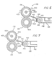
- the downstream end of the guide 412 is at nearly the same height as the nip position of the fixing roller pair. Accordingly, the sheet material is conveyed as shown by a two-dot chain line in Figure 7 and conveyed to the nip position of the fixing roller pair nearly in a straight line fashion without being bent by the downstream end of the guide 412. Thus, sheet jamming and disturbance of the unfixed toner image, which may occur when a sheet material having relatively high stiffness is used, can be prevented.
- a sheet material having a relatively small width (more specifically, smaller than the width of the specified area in the transverse direction) and relatively low stiffness (generally sheet materials having relatively low stiffness have a small weight) is used.
- the sheet material in this case is brought to the nip position of the fixing roller pair while being guided by the upper surface of the guide 412 (specified area). But since its weight is small, the downstream end portion of the guide 412 is not so much bent downwardly when the sheet material is guided over the upper surface of the guide 412.
- the sheet material is raised by being guided by the upper surface of the guide 412 and then lowered and conducted to the nip position of the fixing roller pair.
- the sheet material is conveyed as shown by a two-dot chain line in Figure 5 and bent by the downstream end of the guide 412. Creases in the sheet material will be straightened by this bending action. In this case, too, the sheet material can be passed between the fixing rollers after its creases have been removed.
- the guide 412 (specified area) is disposed in the central portion of the guiding portion of the guide member 408 in the widthwise direction.
- the guide 412 may be provided in the left side portion (or the right side portion) in the widthwise direction of the guiding portion of the guide member 408.
- the above embodiment is applied to a fixing device including an electrical heating element. It can, however, be also applied to a fixing device of the pressure type which is adapted to fix the toner image on the sheet material only by the pressure between the fixing rollers.
Landscapes
- Physics & Mathematics (AREA)
- General Physics & Mathematics (AREA)
- Fixing For Electrophotography (AREA)
- Paper Feeding For Electrophotography (AREA)
Description
- This invention relates to improvements in an electrostatic copying apparatus and specifically to a fixing device as mentioned in the preamble portion of claim 1. Such a fixing device is known from JP-A-57/176 077.
- Electrostatic copying apparatuses of the so-called shell type including a lower supporting frame and an upper supporting frame mounted for free pivotal movement between an open position and a closed position have been proposed and come into practical application. Generally, in such a shell-type electrostatic copying apparatus, when the upper supporting frame is held at the open position, at least a considerable portion of a conveying passage for a sheet material such as a copying paper is opened. Hence, if jamming of the sheet material should occur in the conveying passage, it can be easily taken out. However, the conventional shell-type electrostatic copying apparatuses have certain problems to be solved.
- It is desired to vary the state of feeding of a sheet material bearing a toner image to the upper and lower rollers depending upon the nature of the sheet material, for example upon whether it is relatively light and has relatively low stiffness as in an ordinary copying paper or whether it is relatively heavy and has relatively high stiffness as in an official postal card. This desire cannot be fully achieved.
- JP-A-57/176 077 discloses a fixing device comprising a fixing roller pair composed of an upper and a lower roller cooperating with each other and a guide member disposed upstream of the fixing roller pair, said guide member having a guide portion extending downstream with its downstream end located in proximity to the peripheral surface of the upper roller pair, the upper surface of the guide portion being adapted to guide a sheet material having on its surface a toner image to be fixed to the fixing roller pair.
- It is the object of this invention to provide a fixing device in which the state of feeding of a sheet material bearing a toner image to be developed to an upper and a lower roller is varied automatically in the required manner according to the characteristic of the sheet material.
- The object is solved by the features of claim 1, further advantageous developments of the invention are described in the dependent claims.
- Other objects and advantages of this invention will become apparent from the following description of embodiments of the invention.
- Figure 1 is a simplified longitudinal sectional view showing one embodiment of the electrostatic copying apparatus constructed in accordance with this invention;
- Figure 2 is a simplified cross sectional view of the electrostatic copying apparatus of Figure 1;
- Figure 3 is a simplified view showing a driving system of the electrostatic copying apparatus of Figure 1;
- Figure 4 is a simplified view showing a part of the driving system of Figure 3;
- Figure 5 is a sectional view showing the vicinity of a fixing device;
- Figure 6 is a perspective view showing a guide member;
- Figure 7 is a sectional view showing the state in which as sheet material having relatively high stiffness is used.
- The entire structure of one embodiment of the electrostatic copying apparatus which has been improved in various respects in accordance with this invention will first be described.
- With reference to Figure 1, the illustrated copying apparatus has a nearly rectangular parallelpipedal housing shown generally at 2. The housing 2 is defined by a lower supporting
frame 4 and an upper supportingframe 6. With reference to Figure 2 together with Figure 1, the lower supporting frame includes a verticalfront base plate 8 and a verticalrear base plate 10 disposed with a predetermined distance there-between in the front-rear direction (a direction perpendicular to the sheet surface in Figure 1, and the left-right direction in Figure 2), and abottom plate 12 fixed to the lower ends of these plates. Thebottom plate 12 has abottom wall portion 14 defining the bottom surface of the housing 2 and lowersurface wall portions frame 6 includes a verticalfront base plate 20 and a verticalrear base plate 22 disposed with a predetermined distance there-between in the front-rear direction and atop plate 24 fixed to the upper ends of these Plates. Thetop plate 24 has atop wall portion 26 defining the top surface of the housing 2 and uppersurface wall portions frame 6 is mounted on the lower supportingframe 4 so that it can pivot freely between a closed position shown by solid lines in Figures 1 and 2 and an open position shown by two-dot chain lines in Figures 1 and 2. More specifically, upwardly extending supportingprojections 32 are provided at the right end portions of the verticalfront base plate 8 and the verticalrear base plate 10 of the lower supportingframe 4, and the verticalfront base plate 20 and the verticalrear base plate 22 of the upper supportingframe 6 are pivotally mounted on these supportingprojections 32 through ashaft 34. Normally, the upper supportingframe 6 is locked in the closed position shown by the solid lines in Figures 1 and 2 by a suitable locking mechanism (not shown), but as required, can be pivoted to the open position shown by the two-dot chain lines in Figures 1 and 2 with theshaft 34 as a center by cancelling the locking action of the locking mechanism. - In the illustrated copying apparatus, there are also provided a
front cover 36 covering the front surface of the housing 2 and arear cover 38 for covering the rear surface of the housing 2, as shown in Figure 2. Thefront cover 36 is comprised of alower front cover 40 fixed to the lower supportingframe 4 and anupper front cover 42 fixed to the upper supportingframe 6. Likewise, therear cover 38 is comprised of a lowerrear cover 44 fixed to the lower supportingframe 4 and an upperrear cover 46 fixed to the upper supportingframe 6. Accordingly, when the upper supportingframe 6 is moved from the closed position to the open position, approximately the upper half portions of thefront cover 36 and therear cover 38, i.e. theupper front cover 42 and the upperrear cover 46, can be moved to the open position in the same way. - A document placing means shown generally at 48 is disposed on the top surface of the housing 2 so that it can reciprocate freely in the left-right direction in Figure 1 or a direction perpendicular to the sheet surface in Figure 2. As clearly shown in Figure 2, the document placing means 48 which may be in a form known per se includes a supporting
base plate 50, atransparent plate 52 fixed to the supportingbase plate 50, and a document cover 54 (omitted in Figure 1) whose rear edge (left edge in Figure 2) is pivotably mounted on the supportingbase plate 50 by a suitably mechanism (not shown). With reference to Figure 2, the method of mounting the document placing means 48 will be described. A supportingmember 58 having ahorizontal portion 56 is fixed to the rear surface of the verticalrear base plate 22 of the upper supportingframe 6, and between thehorizontal portion 56 of the supportingmember 58 and the supportingbase plate 50 of the document placing means 48 is interposed a sliding mechanism 60 (which may conveniently be one commercially available under the tradename "Aculide") extending in the reciprocating direction of the document placing means 48. On the other hand, aguide member 62 having a rearwardly opened guide groove at its upper portion extending upwardly beyond the top surface of the housing 2 is fixed to the front surface of the verticalfront base plate 20 of the upper supportingframe 6. The front edge portion of thetransparent plate 52 of the document placing means 48 is slidably received in the guide groove of theguide member 62. Thus, the document placing means 48 is mounted such that it can freely reciprocate between a start-of-scan position shown by a two-dot chain line 48A in Figure 1 and a scan movement limit position shown by a two-dot chain line 48B in Figure 1. - With reference to Figure 1, a rotating drum 64 having a photosensitive member on its peripheral surface is rotatably mounted nearly centrally within the housing 2. Areound the rotating drum 64 adapted to be rotated in the direction of an
arrow 66 are disposed a chargingcorona discharge device 68, an optical unit 70, a latent electrostaticimage developing device 72, a transferringcorona discharge device 74, a peelingcorona discharge device 76, acleaning device 80 having acleaning blade 78 and a charge eleminatinglamp 82 in this sequence in the rotating direction of the drum 64. In relation to the optical unit 70, adocument illuminating lamp 84 is also provided. Thedocument illuminating lamp 84 illuminates a document (not shown) to be copied, placed on thetransparent plate 52 of the document placing means 48, through anopening 86 formed at thetop wall portion 26 of thetop plate 24. The optical unit 70 is constructed by arranging many elongate optical elements extending in the vertical direction (for example, rod-like lenses sold under the tradename "Selfox Microlense" by Nippon Sheet Glass Co., Ltd.), and as shown by an arrow in Figure 1, projects the reflected light from the document onto the peripheral surface of the rotating drum 64. - A sheet material conveying device shown generally at 88 is disposed in the nearly lower half portion of the housing 2. At one end (the right end in Figure 1) of the sheet
material conveying device 88 are provided a cassette-type copyingpaper feed device 90 and a manualsheet feed device 92. The copyingpaper feed device 90 consists of a combination of a papercassette receiving section 96 having afeed roller 94 provided therein and apaper cassette 100 to be loaded in the papercassette receiving section 96 through anopening 98 formed on the right side surface of the housing 2 (more specifically the right side lowersurface wall portion 16 of the bottom plate 12), and feeds copying paper sheets one by one from acopying sheet layer 102 accommodated in thecassette 100 by the action of thefeed roller 94. Themanual feed device 92 includes aguide plate 106 protruding outwardly through anopening 104 formed in the right side surface of the housing 2, aguide plate 108 located above theguide plate 106, and a pair offeed rollers guide plates guide plate 106 and advanced to the nipping position of thefeed rollers feed rollers paper feed device 90 between theguide plates manual feed device 92 between theguide plates guide plates conveying rollers 120 and 122 and conveyed to a position between the rotating drum 64 and the transferringcorona discharge device 74 and the peelingcorona discharge device 76. Then, by the action of a suitableconveying belt mechanism 128, it is sent to afixing device 130. Thereafter, it is discharged into a receivingtray 134 through anopening 132 formed in the left side surface of the housing 2 (more specifically, the left side lowersurface wall portion 18 of the bottom plate 12). Thefixing device 130 includes a fixing roll pair comprised of anupper roller 136 and alower roller 138 cooperating with each other (the structure of thefixing device 130 will be described in detail hereinafter). The sheet material from the fixing roller is discharged into the receivingtray 134 by the action of a pair ofdischarge rollers - Thus, it will be easily understood with reference to Figure 1 that the
guide plate 108, thefeed roller 110, theguide plate 118, theconveying roller 120 and theguide plate 124 in the sheetmaterial conveying device 88 are mounted on the upper supportingmember 6 together with the rotating drum 64, the chargingcorona discharge device 68, the optical unit 70, the developingdevice 72, the cleaning means 80, thecharge eliminating lamp 82 and thedocument illuminating lamp 84. On the other hand, the copyingpaper feed device 90, theguide plate 106, thefeed roller 112, theguide plate 114, theguide plate 116, the conveying roller 122, theguide plate 126, the transferringcorona discharge device 74, the peelingcorona discharge device 76, theconveying belt mechanism 128, thefixing device 130 and the receivingtray 134 are mounted on the lower supportingframe 4. Accordingly, when the upper supportingframe 6 is moved from the closed position shown by the solid line to the open position shown by the two-dot chain line, most of the conveying passage for the sheet material is opened, and therefore in the event of jamming, the sheet material can be easily taken out from it. - In the copying apparatus described above, the charging
corona discharge device 68 charges the photo-sensitive member to a specified polarity substantially uniformly while the rotating drum is rotated in the direction ofarrow 66. Then, the image of the document is projected onto the photosensitive member through the optical unit 70 (at this time, the document placing means 48 makes a scanning exposure movement to the right in Figure 1 from the start-of-scan position shown by the two-dot chain line 48A in Figure 1) to form on the photosensitive member a latent electrostatic image corresponding to the document. Thereafter, the developingdevice 72 applies toner particles to the latent electrostatic image on the photosensitive member to develop it to a toner image. Subsequently, a sheet material such as copying paper fed from the copyingpaper feed device 90 or the manualsheet feed device 92 is brought into contact with the photosensitive member, and by the action of the transferringcorona discharge device 74, the toner image on the photosensitve member is transferred to the sheet material. The sheet material is then peeled off from the photosensitive member by the action of the peelingcorona discharge device 76. The sheet material having the toner image transferred thereto is then conveyed to thefixing device 130 where the toner image is fixed. The sheet material having the fixed toner image is then discharged into the receivingtray 134. In the meantime, the rotating drum 64 continues to rotate. The residual toner particles are removed from the photosensitive member by the action of thecleaning device 80, and the residual charge on the photosensitive member is erased by the action of thecharge eliminating lamp 82. - With reference to Figure 3 in conjunction with Figure 1, the driving system in the illustrated copying apparatus will be described in summary.
- In the illustrated copying apparatus, a driving
source 144 which may be an electric motor is provided in the upper supportingframe 6. In relation to the drivingsource 144, apower transmission mechanism 146 for the rotating drum and an interlockingpower transmission mechanism 148 are provided in the upper supportingframe 6. Thepower transmission mechanism 146 for the rotating drum includes atoothed pulley 150 fixed to the output shaft of the drivingsource 144, atoothed pulley 152 linked to the rotating drum 64, a rotatably mounted tensioningtoothed pulley 154, and atiming belt 156 wrapped about thesetoothed pulleys power transmission mechanism 148 includes asprocket wheel 158 fixed to the output shaft of the drivingsource 144, a rotatably mounted sprocket wheel 160, asprocket wheel 162 mounted coaxially, and rotatably as a unit, with the sprocket wheel 160, and achain 164 wrapped about thesprocket wheels 158 and 160. - The upper supporting
frame 6 further has provided therein apower transmission mechanism 166 for the document placing means and apower transmission mechanism 168 for the developing device. Thepower transmission mechanism 166 for the document placing means includes agear 170 mounted coaxially with, and rotatably as a unit with, thetoothed pulley 152 in thepower transmission mechanism 146 for the rotating drum, a double clutch means 176 comprising a clutch means 172 for normal motion and a clutch means 174 for reverse motion, agear 178, apinion gear 180, and a rack 182 (Figures 2 and 4) fixed to the lower surface of the supportingbase plate 50 of the document placing means 48. With reference to Figures 3 and 4 in conjunction with Figure 1, the clutch means 172 for normal motion has aninput gear 183 in mesh with thegear 170, and the clutch means 174 for reverse motion has anoutput gear 185 in mesh with thegear 178. The double clutch means 176 comprised of the clutch means 172 and 174 may be substantially the same as the double electromagnetically controlled spring clutch mechanism disclosed in the specification and drawings of co-pending Japanese Patent Appli-ation No. 47120/1983 entitled "Electromagnetically Controlled Spring Clutch Mechanism" filed March 23, 1983. Accordingly, the specification and drawings of the above application are cited as reference instead of giving a detailed description of the structure of the double clutch means 176. - The
gear 178 is engaged with thepinion gear 180, and thepinion gear 180 is engaged with therack 182 extending in the reciprocating direction (the left-right direction in Figures 1, 3 and 4) of the document placing means 48. When the drivingsource 144 is energized and thegear 170 is rotating in the direction ofarrow 66, actuation of the clutch means 172 for normal motion causes thegear 178 and thepinion gear 180 to rotate in the direction shown by anarrow 184, and consequently the document placing means 48 is moved at a predetermined speed V in the direction ofarrow 184. On the other hand, when the clutch means 174 for reverse motion is actuated at this time, thegear 178 and thepinion gear 180 are rotated in the direction of anarrow 186, and consequently, the document placing means 48 is moved at a speed double the speed V, i.e. 2V, in the direction ofarrow 186. - The
power transmission mechanism 168 for the developingdevice 168 includes agear 188 rotated coaxially with, and rotatably as a unit with, thesprocket wheels 160 and 162 in the interlockingpower transmission mechanism 148, agear 190 engaged with thegear 188 and agear 192 engaged with thegear 190. Thegear 190 is connected to a sleeve member (to be described hereinafter) provided in the developingdevice 72. - A
power transmission mechanism 194 which has to do with the conveying of a sheet material is mounted on the lower supportingframe 4. Thepower transmission mechanism 194 includessprocket wheels chain 204 wrapped about thesesprocket wheels sprocket wheel 196 is connected to the feed roller 112 (Figure 1). Thesprocket wheel 196 also has provided therein agear 206 coaxially, and rotatably as a unit, with thesprocket wheel 196. Agear 208 is engaged with thegear 206, and thegear 208 is connected to the feed roller 94 (Figure 1) in thepaper feed device 90 through a suitable clutch means (not shown) electromagnetically controlled. Thesprocket wheel 198 is connected to the conveying roller 122 through a suitable electromagnetically controlled clutch means (not shown). Thesprocket wheel 200 is provided so as to keep thechain 204 taut. Thesprocket wheel 202 is connected to a driven roller 416 (Figure 1) in the conveyingbelt mechanism 128. Thesprocket wheel 202 has attached thereto agear 210 coaxial, and rotatably as a unit, with it. Agear 212 is in mesh with thegear 210, and agear 214 is in mesh with thegear 212. Agear 216 and agear 218 are kept in mesh with thegear 214, and agear 220, with thegear 218. Thegear 216 is linked to the upper roller 136 (Figure 1) of the fixingdevice 130, and thegear 220, to adischarge roller 142. - It will be readily understood from Figures 1 and 3 that when the upper supporting
frame 6 is held at the closed position, thesprocket wheel 162 of the interlockingpower transmission mechanism 148 provided in the upper supportingframe 6 is engaged with thechain 204 of thepower transmission mechanism 194 provided in the lower supportingframe 4 and consequently, the drivingsource 144 is drivingly connected to thepower transmission mechanism 194 through the interlockingpower transmission mechanism 148. On the other hand, when the upper supportingframe 6 is moved to the open position shown by the two-dot chain line in Figure 1, thesprocket wheel 162 of the interlockingpower transmission mechanism 148 is brought out of engagement with thechain 204 of thepower transmission mechanism 194. - In the fixing device used in the electrostatic copying apparatus described above, a toner image on a sheet meterial is fixed on its surface by conveying the sheet material having the toner image transferred in the transferring zone between a pair of fixing rollers. Generally, in such a fixing device, the downstream end of a guide member provided upstream of the pair of fixing rollers for guiding the sheet material to the fixing rollers (i.e., that end of the guide member which is in proximity to the pair of fixing rollers) is positioned above the nip position of the pair of fixing rollers. When the downstream end of the guide member is so positioned, a sheet material of relatively low stiffness which is frequently used is bent by the downstream end of the guide member, and by this bending action, creases of that portion of the sheet material which is introduced between the fixing rollers are straightend, and it is possible to prevent the occurrence of creases on the sheet material during fixing by the fixing rollers. On the other hand, when a sheet material having relatively high stiffness [for example, an official postal card (which is not often used)) is used, the leading end of the sheet material contacts the upper fixing roller in the fixing roller pair and conveying of the sheet material may fail (jamming occurs). Or the trailing end portion of the sheet may abruptly rise upstream of the downstream end of the guide member to disturb the unfixed toner image on the sheet material.
- In an attempt to remove the foregoing inconvenience, Japanese Laid-Open Utility Model Publication No. 66947/1978, for example, proposes a fixing device in which a notch or a depressed portion is formed centrally in the downstream end of a guide member for guiding a sheet material to a pair of fixing rollers so that the central portion of the sheet material carried between the fixing rollers can sag down. Elsewhere, Japanese Laid-Open Utility Model Publication No. 3558/1981 proposes a fixing device in which a guide portion for conducting a sheet material having relatively high stiffness to the nipping position of a pair of fixing rollers is provided in a guide member for guiding a sheet material to the fixing rollers.
- In the fixing devices disclosed in the specifications of Japanese Laid-Open Utility Model Publications Nos. 66947/1978 and 3558/1981, a sheet material having a relatively small size and relatively high stiffness can be conveyed to near the nip position of the pair of fixing rollers, and the toner image can be fixed on it well. But a sheet material having a relatively small size and relatively low stiffness is not bent at the downstream end of the guide member and creases are likely to form on the sheet material during fixing by the pair of fixing rollers.
- The fixing device constructed in accordance with the present invention has the following improvement in order to remove the aforesaid inconvenience.
- With reference to Figures 5 to 6, the fixing device improved in accordance with this invention will be described below in detail.
- With reference to Figure 5, the fixing
device 130 has a fixing roller pair composed of anupper roller 136 and alower roller 138 cooperating with each other. In the illustrated embodiment, theupper roller 136 to be driven in the direction of anarrow 403 is constructed of acylindrical sleeve member 402 made of aluminum having a surface coated with "Teflon" (a tradename for polytetrafluoroethylene made by E. I. du Pont de Nemours & Co.), and thelower roller 138 is constructed of ametallic pipe member 404 surface-coated with rubber, etc. Within theupper roller 136 is disposed anelectrical heating element 406 such as an electric heater for fixing the toner image on the sheet material under heat. - Upstream of the fixing roller pair is disposed a
guide member 408 for conducting a sheet material conveyed by the action of theconveyer belt mechanism 128 to the fixing roller pair. As shown in Figure 6, theguide member 408 has amain guide 410 formed of a rigid material such as a metallic material and aguide 412 made of a flexible material. Themain guide 410 has a securing portion 410a (constituting the securing portion of the guide member 408) and a guidingportion 410b extending from the securing portion 410a. A rectangular cut having a predetermined width is provided in the central part of the guidingportion 410b in the widthwise direction (the direction perpendicular to the sheet surface in Figure 5 and the direction from left bottom to the right top in Figure 6 ) (more specifically, the cut is formed from the upstream end to the downstream end of the guiding portion 410). Theguide 412 is disposed in the aforesaid cut by fixing its upstream end to the securing portion 410a of themain guide 410. Thus, theguide 412 and the guidingportion 410b of themain guide 410 constitutes the guiding portion of theguide member 408, and theguide 412 defines a specified area of the guiding portion of theguide member 408. Preferably, the upper surface of theguide 412 is disposed in the same plane as the upper surface of the guidingportion 410b of themain guide 410. Preferably, theguide 412 of a flexible material is a polyester film having a thickness of about 0.1 mm (for example, those commercially available under the tradenames "Lumilar" and "Mylar"). In the illustrated embodiment, a sheet material having relatively high stiffness is assumed to be an official post card, and the width of the aforesaid specified area is set at about 100 mm (substantially equal to, or slightly larger than, the width of the official post card). - The
guide member 408 consisting of themain guide 410 and theguide 412 is fixed to a supporting vertical wall provided in thebottom wall portion 14 which defines the bottom surface of the housing 2 (Figure 1). As is clear from Figure 5, the guiding portion of theguide member 408 extends upwardly inclinedly toward the downstream side (more specifically, toward the downstream side in the conveying direction of the sheet material shown by an arrow 414), and its lower end portion is positioned slightly above the nip position of the fixing roller pair (theupper roller 136 and the lower roller 138) and in proximity to the peripheral surface of theupper roller 136. The upstream end (that end which is in proximity to the conveying belt mechanism 128) of the guiding portion of theguide member 408 is positioned below the nip position of the fixing roller pair. - The illustrated conveying
belt mechanism 128 includes a pair of rollers 416 (Figure 1) and an endless conveyingbelt 418 having a plurality of holes formed therein. Theconveyor belt 418 is stretched across therollers 416, and asuction chamber 420 is disposed between the upper portion (the portion acting for conveying the sheet material) and the lower portion of theconveyor belt 418. That surface of thesuction chamber 420 which faces the upper portion of theconveyor belt 418 is opened. The inside of thesuction chamber 420 is sucked by a suction motor (not shown), and by the sucking action of the suction motor, the sheet material conveyed on the upper portion of theconveyor belt 418 is attracted to theconveyor belt 418. - In the
fixing device 130 described above, the sheet material having a toner image on its upper surface which is conveyed on theconveyor belt 418 is conducted to the fixing roller pair by being guided by the upper surface of the guiding portion of theguide member 408. By the fixing action of the fixing roller pair, the toner image is fixed to the surface of the sheet material. - The operation and advantage of the fixing
device 130 including theguide member 408 described above will be described with reference to Figures 5 to 7 . - Let us first assume that a sheet material having a relatively large width (more specifically larger than the width of the aforesaid specified area in the transverse direction) is used. As can be easily understood from Figure 6, the sheet material is raised while being guided mainly by the upper surface of the guiding
portion 410b of themain guide 410 of theguide member 408, and thereafter, lowered and conducted to the nip position of the fixing roller pair (theupper roller 136 and the lower roller 138). Accordingly, the sheet material is conveyed as shown by a two-dot chain line in Figure 5 and bent by the downstream end of the guidingportion 410b of themain guide 410. Creases will be straightened by this bending action. As a result, the sheet material can be introduced between the fixing rollers after its creases have been removed, and the occurrence of creases in the sheet material during the fixing operation can be prevented. - Now, let us assume that a sheet material having a relatively small width (more specifically smaller than the width of the aforesaid specified area in the transverse direction) and relatively high stiffness (generally sheet materials having relatively high stiffness mostly have a large weight), for example, an official post card, is used. As can be readily understood from Figure 6, the sheet material is conducted to the nip position of the fixing roller pair by being guided by the upper surface of the guide 412 (the specified area). When the sheet material is guided over the upper surface of the
guide 412, the downstream end portion of theguide 412 is bent downwardly by the weight of the sheet material as shown in Figure 7 because theguide 412 is made of a flexible material. Thus, the downstream end of theguide 412 is at nearly the same height as the nip position of the fixing roller pair. Accordingly, the sheet material is conveyed as shown by a two-dot chain line in Figure 7 and conveyed to the nip position of the fixing roller pair nearly in a straight line fashion without being bent by the downstream end of theguide 412. Thus, sheet jamming and disturbance of the unfixed toner image, which may occur when a sheet material having relatively high stiffness is used, can be prevented. - Now, let us assume that a sheet material having a relatively small width (more specifically, smaller than the width of the specified area in the transverse direction) and relatively low stiffness (generally sheet materials having relatively low stiffness have a small weight) is used. The sheet material in this case is brought to the nip position of the fixing roller pair while being guided by the upper surface of the guide 412 (specified area). But since its weight is small, the downstream end portion of the
guide 412 is not so much bent downwardly when the sheet material is guided over the upper surface of theguide 412. The sheet material is raised by being guided by the upper surface of theguide 412 and then lowered and conducted to the nip position of the fixing roller pair. Accordingly, the sheet material is conveyed as shown by a two-dot chain line in Figure 5 and bent by the downstream end of theguide 412. Creases in the sheet material will be straightened by this bending action. In this case, too, the sheet material can be passed between the fixing rollers after its creases have been removed. - In the embodiment described above, the guide 412 (specified area) is disposed in the central portion of the guiding portion of the
guide member 408 in the widthwise direction. When a sheet material having a relatively small size is to be guided on the upper surface of the left side portion (or the right side portion) in the widthwise direction of the guiding portion of theguide member 408, theguide 412 may be provided in the left side portion (or the right side portion) in the widthwise direction of the guiding portion of theguide member 408. - The above embodiment is applied to a fixing device including an electrical heating element. It can, however, be also applied to a fixing device of the pressure type which is adapted to fix the toner image on the sheet material only by the pressure between the fixing rollers.
Claims (5)
- A fixing device for a sheet material having on its surface a toner image to be fixed comprising a fixing roller pair composed of an upper (136) and a lower roller (138) cooperating with each other and a guide member (408) disposed upstream of the fixing roller pair as seen in the conveying direction of the sheet material, said guide member (408) having a guide portion (412, 410b) with its downstream end located in proximity to the peripheral surface of the upper roller pair, the guide portion being adapted to guide the sheet material to fixing roller pair,
characterized in that
the guide portion is formed in a specified area (412) of predetermined width of a flexible material having its upstream end fixed, and in the other area of a rigid material, and in that
the downstream end of the specified area is held approximately at the same level as the nip position of the fixing roller pair, whereby the specified area is bent downwardly by the weight of the sheet material when a relatively heavy sheet material with relatively high stiffness passes only along the specified area. - The device of claim 1 wherein the guide portion of the guide member (408) extends upwardly inclinedly toward the downstream side.
- The device of claim 2 wherein the upstream end of the guide member (408) is located below the nip position of the fixing roller pair (136, 138).
- The device of one of claims 1 to 3 wherein the specified area exists centrally in the guide portion (408) in the widthwise direction.
- The device of one of claims 1 to 4 wherein the specified area is formed of a polyester film having a thickness of about 0.1 mm.
Priority Applications (2)
| Application Number | Priority Date | Filing Date | Title |
|---|---|---|---|
| EP92108616A EP0511685B1 (en) | 1983-04-12 | 1984-04-12 | Electrostatic copying apparatus |
| EP19870115898 EP0264968B1 (en) | 1983-04-12 | 1984-04-12 | Electrostatic copying apparatus |
Applications Claiming Priority (3)
| Application Number | Priority Date | Filing Date | Title |
|---|---|---|---|
| JP63051/83 | 1983-04-12 | ||
| JP58063051A JPS59188630A (en) | 1983-04-12 | 1983-04-12 | Electrostatic copying machine |
| EP19870115898 EP0264968B1 (en) | 1983-04-12 | 1984-04-12 | Electrostatic copying apparatus |
Related Parent Applications (1)
| Application Number | Title | Priority Date | Filing Date |
|---|---|---|---|
| EP84104100.7 Division | 1984-04-12 |
Related Child Applications (2)
| Application Number | Title | Priority Date | Filing Date |
|---|---|---|---|
| EP92108616A Division EP0511685B1 (en) | 1983-04-12 | 1984-04-12 | Electrostatic copying apparatus |
| EP92108616.1 Division-Into | 1992-05-21 |
Publications (3)
| Publication Number | Publication Date |
|---|---|
| EP0264968A2 EP0264968A2 (en) | 1988-04-27 |
| EP0264968A3 EP0264968A3 (en) | 1989-05-31 |
| EP0264968B1 true EP0264968B1 (en) | 1993-07-21 |
Family
ID=26108634
Family Applications (2)
| Application Number | Title | Priority Date | Filing Date |
|---|---|---|---|
| EP92108616A Expired - Lifetime EP0511685B1 (en) | 1983-04-12 | 1984-04-12 | Electrostatic copying apparatus |
| EP19870115898 Expired - Lifetime EP0264968B1 (en) | 1983-04-12 | 1984-04-12 | Electrostatic copying apparatus |
Family Applications Before (1)
| Application Number | Title | Priority Date | Filing Date |
|---|---|---|---|
| EP92108616A Expired - Lifetime EP0511685B1 (en) | 1983-04-12 | 1984-04-12 | Electrostatic copying apparatus |
Country Status (1)
| Country | Link |
|---|---|
| EP (2) | EP0511685B1 (en) |
Families Citing this family (3)
| Publication number | Priority date | Publication date | Assignee | Title |
|---|---|---|---|---|
| DE4305910A1 (en) * | 1993-02-26 | 1994-09-01 | Beiersdorf Ag | Self-adhesive capping film for packaging electronic components |
| KR960010183B1 (en) * | 1993-10-23 | 1996-07-26 | 김광호 | Image recording apparatus and control method thereof for energy economization |
| US5962861A (en) * | 1997-02-26 | 1999-10-05 | Hewlett-Packard Company | Sheet media weight detector and method |
Family Cites Families (8)
| Publication number | Priority date | Publication date | Assignee | Title |
|---|---|---|---|---|
| US4046990A (en) * | 1975-04-07 | 1977-09-06 | Eastman Kodak Company | Temperature sensing and control of a fusing roll |
| JPS52127341A (en) * | 1976-04-19 | 1977-10-25 | Canon Inc | Fixing device for copying machne for electronic photography |
| JPS5642682Y2 (en) * | 1976-11-05 | 1981-10-06 | ||
| EP0006553A1 (en) * | 1978-07-03 | 1980-01-09 | International Business Machines Corporation | Method and apparatus for operating a heat source in a reproduction machine |
| JPS563558U (en) * | 1979-06-18 | 1981-01-13 | ||
| JPS5692558A (en) * | 1979-12-27 | 1981-07-27 | Toshiba Corp | Copying machine |
| JPS5790659A (en) * | 1980-11-27 | 1982-06-05 | Canon Inc | Image former |
| JPS57176077A (en) * | 1981-04-23 | 1982-10-29 | Fuji Xerox Co Ltd | Fixing device of electronic copying machine |
-
1984
- 1984-04-12 EP EP92108616A patent/EP0511685B1/en not_active Expired - Lifetime
- 1984-04-12 EP EP19870115898 patent/EP0264968B1/en not_active Expired - Lifetime
Also Published As
| Publication number | Publication date |
|---|---|
| EP0264968A2 (en) | 1988-04-27 |
| EP0511685A1 (en) | 1992-11-04 |
| EP0264968A3 (en) | 1989-05-31 |
| EP0511685B1 (en) | 1996-08-14 |
Similar Documents
| Publication | Publication Date | Title |
|---|---|---|
| EP0195181A2 (en) | Electrostatic copying apparatus | |
| US4711550A (en) | Electrostatic copying apparatus | |
| US5120038A (en) | Automatic document conveying device for an image processing machine | |
| EP0125497B1 (en) | Electrostatic copying apparatus | |
| GB2088833A (en) | Electrophotographic copier with copy paper supply device | |
| EP0264968B1 (en) | Electrostatic copying apparatus | |
| US5064188A (en) | Automatic document conveying device which opens so jams may be cleared | |
| US4875077A (en) | Image-forming machine | |
| JPH07191557A (en) | Image forming device | |
| JP2932548B2 (en) | Paper transport device | |
| US4629307A (en) | Image forming apparatus with jammed paper access opening | |
| US4569581A (en) | Small electrophotographic copying machine with transparent film | |
| EP0262692B1 (en) | Electrostatic copying apparatus | |
| JP2602864B2 (en) | Document feeder | |
| JP2920647B2 (en) | Electrostatic printing device | |
| JPH08297382A (en) | Image forming device provided with original transporting device | |
| JP2967584B2 (en) | Electrostatic printing device | |
| JPH0213404Y2 (en) | ||
| KR920005086Y1 (en) | Fixing apparatus for copying machine | |
| EP0329197B1 (en) | Electrostatic copying apparatus | |
| JP3734525B2 (en) | Static eliminator for electrostatic copying machine | |
| JPH0454978Y2 (en) | ||
| JP3261277B2 (en) | Image forming apparatus provided with document feeder | |
| JPH0246948B2 (en) | 2SHUNOINATSUTAYOSHIKIDESHOSHIURUGENKOSAICHIKIKOOSONAETASEIDENFUKUSHASOCHI | |
| JPH08171240A (en) | Image forming device provided with document feeder |
Legal Events
| Date | Code | Title | Description |
|---|---|---|---|
| PUAI | Public reference made under article 153(3) epc to a published international application that has entered the european phase |
Free format text: ORIGINAL CODE: 0009012 |
|
| AC | Divisional application: reference to earlier application |
Ref document number: 125497 Country of ref document: EP |
|
| AK | Designated contracting states |
Kind code of ref document: A2 Designated state(s): DE FR GB NL |
|
| PUAL | Search report despatched |
Free format text: ORIGINAL CODE: 0009013 |
|
| AK | Designated contracting states |
Kind code of ref document: A3 Designated state(s): DE FR GB NL |
|
| 17P | Request for examination filed |
Effective date: 19890927 |
|
| 17Q | First examination report despatched |
Effective date: 19911128 |
|
| GRAA | (expected) grant |
Free format text: ORIGINAL CODE: 0009210 |
|
| AC | Divisional application: reference to earlier application |
Ref document number: 125497 Country of ref document: EP |
|
| AK | Designated contracting states |
Kind code of ref document: B1 Designated state(s): DE FR GB NL |
|
| RIN1 | Information on inventor provided before grant (corrected) |
Inventor name: KISHIMOTO, KEIICHI Inventor name: UMEDA, TADASHI Inventor name: AKIYAMA, KAZUNORI Inventor name: HYODO, KEIICHIRO Inventor name: OHATA, YOSUKE Inventor name: IIDA, KAZUMI |
|
| XX | Miscellaneous (additional remarks) |
Free format text: TEILANMELDUNG 92108616.1 EINGEREICHT AM 12/04/84. |
|
| ET | Fr: translation filed | ||
| REF | Corresponds to: |
Ref document number: 3486181 Country of ref document: DE Date of ref document: 19930826 |
|
| PLBE | No opposition filed within time limit |
Free format text: ORIGINAL CODE: 0009261 |
|
| STAA | Information on the status of an ep patent application or granted ep patent |
Free format text: STATUS: NO OPPOSITION FILED WITHIN TIME LIMIT |
|
| 26N | No opposition filed | ||
| PGFP | Annual fee paid to national office [announced via postgrant information from national office to epo] |
Ref country code: GB Payment date: 19950404 Year of fee payment: 12 |
|
| PGFP | Annual fee paid to national office [announced via postgrant information from national office to epo] |
Ref country code: DE Payment date: 19950410 Year of fee payment: 12 |
|
| PGFP | Annual fee paid to national office [announced via postgrant information from national office to epo] |
Ref country code: FR Payment date: 19950411 Year of fee payment: 12 |
|
| PGFP | Annual fee paid to national office [announced via postgrant information from national office to epo] |
Ref country code: NL Payment date: 19950430 Year of fee payment: 12 |
|
| PG25 | Lapsed in a contracting state [announced via postgrant information from national office to epo] |
Ref country code: GB Effective date: 19960412 |
|
| PG25 | Lapsed in a contracting state [announced via postgrant information from national office to epo] |
Ref country code: NL Effective date: 19961101 |
|
| GBPC | Gb: european patent ceased through non-payment of renewal fee |
Effective date: 19960412 |
|
| PG25 | Lapsed in a contracting state [announced via postgrant information from national office to epo] |
Ref country code: FR Effective date: 19961227 |
|
| PG25 | Lapsed in a contracting state [announced via postgrant information from national office to epo] |
Ref country code: DE Effective date: 19970101 |
|
| NLV4 | Nl: lapsed or anulled due to non-payment of the annual fee |
Effective date: 19961101 |
|
| REG | Reference to a national code |
Ref country code: FR Ref legal event code: ST |