EP0264964B1 - Méthode et dispositif de traitement d'un signal vidéo - Google Patents
Méthode et dispositif de traitement d'un signal vidéo Download PDFInfo
- Publication number
- EP0264964B1 EP0264964B1 EP87115624A EP87115624A EP0264964B1 EP 0264964 B1 EP0264964 B1 EP 0264964B1 EP 87115624 A EP87115624 A EP 87115624A EP 87115624 A EP87115624 A EP 87115624A EP 0264964 B1 EP0264964 B1 EP 0264964B1
- Authority
- EP
- European Patent Office
- Prior art keywords
- signal
- perspective
- video
- transformed
- key
- Prior art date
- Legal status (The legal status is an assumption and is not a legal conclusion. Google has not performed a legal analysis and makes no representation as to the accuracy of the status listed.)
- Expired - Lifetime
Links
Images


Classifications
-
- H—ELECTRICITY
- H04—ELECTRIC COMMUNICATION TECHNIQUE
- H04N—PICTORIAL COMMUNICATION, e.g. TELEVISION
- H04N5/00—Details of television systems
- H04N5/222—Studio circuitry; Studio devices; Studio equipment
- H04N5/262—Studio circuits, e.g. for mixing, switching-over, change of character of image, other special effects ; Cameras specially adapted for the electronic generation of special effects
- H04N5/272—Means for inserting a foreground image in a background image, i.e. inlay, outlay
- H04N5/275—Generation of keying signals
Definitions
- This invention relates to a method and apparatus for processing a video signal.
- a television picture is a representation in substantially planar form of a scene that is composed by the producer of a television program.
- the scene may be composed of tangible objects, or it may be at least partially synthesized by artificial means, e.g. a television graphics system, so that the source of the video signal representing the scene is not a camera or a film scanner but a frame buffer and a computer used for adjusting the contents of the frame buffer.
- the scene is made up of two component scenes, namely a foreground scene and a background scene, that are combined using a travelling matte technique.
- the foreground scene might contain an annulus against a solid color matter and the background scene a square against a screen of contrasting color, as shown in FIGS. 1(a) and 1(b) respectively, so that when the foreground and background scenes are combined the resulting picture has the appearance shown in FIG. 1(c).
- a transform system operates on the video signal representing a scene, and may be used to carry out a spatial transformation on the scene. For example, the scene may be displaced to the right. If the foreground video signal representing the FIG. 1(a) scene is applied to a transform system which carriers out a transformation on the signal such that the transformed signal represents the scene shown in FIG. 1(d), in which the annulus of the FIG. 1(a) scene has been shifted to the right, then the signal obtained by combining the transformed foreground signal with the background signal might represent the picture shown in FIG. 1(e).
- GB-A-2,117,996 discloses a spatial transformation system having means for transforming a first video signal and associated key signal into a transformed video signal and associated key signal to produce an output video signal and associated key signal.
- FIG. 2 represents a frame-based reverse transform system based on principles that are known at present. It is believed that the FIG. 2 system does not exist in the prior art, and it is being described in order to provide information that will be useful in understanding the invention.
- the transform system shown in FIG. 2 operates by digitizing the input video signal under control of a write clock 10 and writing the resulting sequence of digital words into a frame buffer 12 using addresses generated by a forward address generator 14.
- the input video signal is derived from an analog composite video signal in conventional interlaced format by separating it into its components (normally luminance and chrominance) and digitizing each component.
- the frame buffer 12 therefore has a memory for storing the luminance component and a memory for storing the chrominance components.
- the components are acted on in like manner in the transform system, it is not necessary to consider the components separately.
- the operation of digitizing the video signal effectively resolves each raster line of the picture into multiple pixels, e.g., 720 pixels, that are small, but finite, in area.
- the location of a pixel in the scene can be defined by a two-coordinate display address (U, V) of the input screen (FIG. (1a), e.g.).
- the address space of the video frame buffer is organized so that there is one-to-one correspondence between the display addresses and the memory addresses generated by the forward address generator 14.
- the digital word representing the pixel having the display address (U, V) is written into the frame buffer 12 at a location that has a memory address that can be expressed as (U, V).
- an read address counter 16 operates under control of a read clock 17 to generate a sequence of addresses (X, Y) defining the locations in the output screen (FIG. 1(d)) of the pixels that will be successively addressed.
- the coordinate values X and Y each have the same number of significant digits as the coordinate values U and V respectively. Accordingly, the display addresses (X, Y) define the same possible pixel positions in the output display space as are defined in the input display space by the display addresses (U, V). However, the display addresses (X, Y) are not used directly to read the output video signal from the frame buffer.
- a reverse address generator 18 receives the output scene display addresses (X, Y) and multiplies them by a transform matrix T′ to generate corresponding memory addresses (X′, Y′) which are used to read the video signal from the frame buffer.
- the transform matrix T′ is applied to the reverse address generator 18 by a user interface 19, and defines the nature of the transform that is effected by the reverse transform system.
- the transform matrix would be such that the memory address (X′, Y′) that is generated in response to the display address (X, Y) would be (X+1, Y+1), assuming that the origin of the coordinate system is in the upper left corner of the input and output scene, and values of X and Y increase to the right and downwards respectively.
- the memory address coordinates X′ and Y′ have more significant digits than the display address coordinates X and Y.
- the reverse addresses are applied not only to the frame buffer 12 but also to a video interpolator 20.
- the frame buffer For each reverse address (X′, Y′), the frame buffer outputs the respective digital words representing an array of pixels surrounding the point defined by the reverse address (X′, Y′). For example, the data words representing the four pixels nearest the point defined by the address (X′, Y′) might be provided.
- These four data words are applied to the interpolator 20, and the interpolator combines these four digital words into a single digital output word based on the fractional portion of the address (X′, Y′). For example, using decimal notation, if the least significant digit of each coordinate X and Y is unity but the least significant digit of the coordinates X′ and Y′ is one-tenth, and the counter 16 generates the read address (23, 6) which is converted to a reverse address (56.3, 19.8) by being multiplied by the transform matrix T′, the frame buffer 12 responds to the reverse address (56.3, 19.8) by providing the digital words stored at the addresses (56, 19), (56, 20), (57, 19) and (57, 20) and the interpolator 20 combines them into a single digital output word by weighting them 3:7 in the horizontal direction and 8:2 in the vertical direction.
- This digital word defines the value that is to be generated at the location of the output screen that is defined by the display address (23, 6).
- the range of possible reverse addresses is greater than the range of memory addresses defining locations in the frame buffer 12, so that a validly-generated reverse address might define a location that does not exist in the frame buffer's address space. Therefore, the reverse addresses are also applied to an address limit detector 22 which responds to an invalid reverse address (an address which defines a location outside the address space of the frame buffer 12) by providing a signal which causes a video blanker 24 to inhibit the output signal of the frame buffer.
- the video interpolator 20 and the video blanker 24 is a key channel comprising a key frame buffer 26, a key interpolator 28 and a key blanker 30.
- the background scene is fully obscured by the foreground object, but if a foreground object is only partially transparent (0 ⁇ key ⁇ 1) the background video signal is mixed with the foreground video signal in proportion to the value of the key. Because the foreground scene is transformed by the video channel, it is necessary to transform the key in the identical manner in order to maintain congruence between the foreground scene and the key. Therefore, the key signal is processed in the key channel in the same way as the foreground signal is processed in the video channel. Thus, the key signal undergoes the same spatial transformation and interpolation as the foreground signal, and is subject to the same address limit blanking.
- the transform matrix T′ must be mathematical inverse of the desired spatial transform T, and therefore this known transform system is called a reverse transform system.
- a video effects system having means for transforming a first video signal and associated key signal into a transformed video signal and associated key signal to produce an output video signal and associated key signal characterised by: means for generating a first depth signal associated with the first video signal; means for deriving a perspective signal from the first depth signal; and means for combining the transformed video signal and associated key signal with a second video and key signal as a function of the perspective signal to produce the output video signal and associated key signal.
- a method for processing a video signal comprising the steps of transforming a first video signal and associated key signal into a transformed video signal and associated key signal to produce an output video signal and associated key signal characterised by the step of generating a first depth signal associated with the first video signal; deriving a perspective signal from the first depth signal; and combining the transformed video signal and associated key signal with a second video and key signal as a function of the perspective signal to produce the output video signal and associated key signal.
- FIGS. 2 and 3 like reference numerals designate corresponding components.
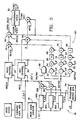
- the special effects system shown in FIG. 3 is based on a reverse transform system. Some elements of the reverse transform system have been omitted from FIG. 3 for the sake of clarity.
- the video channel and the key channel are shown as respective blocks 34 and 36, and the address limit detector is not shown in FIG. 3.
- the reverse address generator is shown in greater detail in FIG. 3 than in FIG. 2.
- the reverse address generator comprises a transform matrix generator 54 which generates the coefficients A - I that compose the reverse transform matrix T′. These coefficients are generated in response to signals received from an operator interface (I/F) indicating the nature of the transformation to be executed.
- the three groups of coefficients A,B,C; D,E,F and G,H,I are applied to respective processing circuits 56X, 56Y and 56Z.
- the processing circuits 56 each receive the address signal (X, Y) from the read address counter 16 and provide as their respective output signals the values AX + BY + C, DX + EY + F and GX + HY + I.
- the output signals of the circuits 56X and 56Y are applied as numerator inputs to respective division circuits 58X and 58Y, each of which receives the output signal of the circuit 56Z as its denominator input.
- the output signals of the circuits 58X and 58Y therefore represent X′ and Y′ respectively and are applied to the video and key channels.
- the coefficients A-F are used for flat transforms (X/Y scaling, X/Y translation or Z-axis rotation)
- the coefficients G-I are functions of the perspective viewpoint and the Z-location of the pixel having the display address (X′, Y′).
- G and H are each zero and I is one and the denominator of each equation is one.
- a non-unity denominator causes the values of X′ and Y′ to vary on a pixel-by-pixel (G not equal to zero), line-by-line (H not equal to zero) and/or field-constant (I not equal to one) basis.
- the denominator of the spatial transformation equations provides a measure of the apparent distance of a pixel from the viewer.
- the signal provided by the processing circuit 56Z and having the value GX + HY + I is representative of the apparent depth of each pixel of the scene represented by the transformed video signal.
- the depth signal is applied to a perspective processor 60 that receives the transformed video and key signals from the video and key channels.
- the perspective processor has four distinct processing channels for the depth signal, namely a perspective dim channel, a perspective fade channel, a perspective clip channel and an intersecting planes channel.
- the depth signal is first applied to a subtraction circuit 62 in which it is subtracted from a signal defining a datum value for the apparent depth.
- the datum value represents the apparent depth of a reference or start plane. If the apparent depth indicated by the depth signal is less than the datum value, this implies that the pixel is closer to the viewpoint than is the start plane, and the output signal of the subtraction circuit 62 is forced to zero and the depth signal has no effect on the output of the perspective dim channel. If the apparent depth indicated by the depth signal is greater than the datum value, the output signal of the subtraction circuit represents the depth of the pixel relative to the start plane.
- the output signal of the subtraction circuit 62 is applied to a multiplier 64, in which the signal representative of relative depth is multiplied by a gain factor.
- the value of the gain factor can range from zero to very large (typically 1024). If the gain factor is less than one, the sensitivity of the following stages to the relative depth value is decreased, whereas if the gain factor is greater than one, the sensitivity is increased.
- the output of the multiplier 64 is applied to a clipper and shaper 66, in which the output signal of the multiplier is limited to a maximum value of 1.0 and shaped so that the output signal of the clipper and shaper 66 has no slope discontinuities.
- a summation circuit 68 an offset value, which controls a static dim, is added to the output signal of the clipper and shaper, and the sum is again clipped to 1.0.
- the resulting control signal is used to drive the control port of a video mixer 70 which receives the output signal of the video channel and black video at its signal ports respectively.
- the mixer 70 is set up so that the output signal from the video channel is passed without change for a control value of zero, black video is passed for a control value of one, and a proportional mix is performed between the output signal of the video channel and black video for control values between zero and one.
- the output of the key channel is not affected by the control signal provided by the perspective dim channel.
- the effect of perspective dim is that an increasing amount of black is mixed with the output signal of the video channel as the control value increases.
- the apparent depth of the scene represented by the output signal of the video channel increases, temporally (frame-by-frame) and/or spatially (line-by-line or pixel-by-pixel), the scene become darker.
- the perspective dim effect is limited to pixels that are at a depth that is greater than that of the start plane.
- the static dim offset establishes a minimum value for the depth control signal provided by the perspective dim channel: even pixels that are at a depth that is less than that of the start plane are subject to the static dim.
- the gain factor applied to the multiplexer 64 determines how rapidly the scene dims as it recedes from the viewer.
- the perspective fade circuit is similar to the perspective dim circuit, except that the control signal is applied to a key mixer 80 instead of to the video mixer 70.
- the output signal of the key blanker of the key channel 36 is passed without change to the background mixer 82 for a control value of zero, a zero key signal is passed to the mixer for a control value of one, and a proportional mix is performed between the output of the key blanker and a zero key for control values between zero and one. Therefore, the key signal provided at the output of the key mixer 80 varies in dependence on the key depth control signal from a minimum value of zero to a maximum value that is equal to the value of the output signal of the key channel.
- the output signals of the video and key mixers 70 and 80 are applied to the background mixer 82 through a video combiner 84.
- the combiner 84 is of the same general type as that described and claimed in EP-A-0 236 943, published 16.09.87, and its operation will be described below. However, for present purposes it is assumed that the combiner has no effect on the output signals of the mixers 70 and 80.
- the opacity of the foreground scene in the picture represented by the full-field output signal of the mixer 82 changes: as the key value is forced towards zero from one, the opacity of the foreground scene decreases, with the result that the background mixer mixes in more background video and makes the foreground scene appear to fade into the background as it recedes from the viewer.
- the datum value, the static fade offset and the gain factor that are applied to the depth signal in the circuits 72, 78 and 74 respectively have analogous effects to the corresponding values applied to the depth signal in the perspective dim channel.
- a single perspective dim/perspective fade channel may be used to generate a depth control signal that is applied selectively to the control port of the mixer 70 and/or to the control port of the mixer 80.
- a television picture is seen in two dimensions as a projection of a scene onto a projection plane.
- the projection occurs relative to the viewpoint.
- the scene is spatially transformed such that pixels move in the Z-direction, whether due to Z-axis translation or X- or Y-axis rotation, there is a possibility that pixels will be transformed to locations that are behind the viewpoint.
- an inverted replica of portions of the transformed scene is created in the projection plane. Since the viewer should not normally be able to see in the projection plane portions of the scene that lie on the other side of the viewer from the projection plane, it is desirable that these wrap-around portions of the scene be blanked. It can be shown that wrap-around occurs when the denominator of the transform equations is negative.
- the sign bit of the depth signal generated by the processing circuit 56Z is applied to one input of an AND gate 86 which receives an on/off signal from the operator interface at its other input.
- the output of the AND gate 86 is applied to the blankers of the video and key channels.
- the sign bit of the depth signal is applied to the blankers and inhibits the video and key signals in the event that the sign bit indicates that the depth signal has a negative value.
- the wrap-around portions of the scene are not suppressed in accordance with the value of the sign bit.
- the priority of two video signals can be adjusted, causing one picture to overlay another, in dependence upon the value of a priority signal.
- the priority signal effectively weights the two key signals in complementary fashion so that by adjusting the value of the priority signal the effective relative value of the key signals can be changed.
- the output signal (DEPTH 1) of the processing circuit 56Z is applied to a subtraction circuit 90 which receives at its other input a signal (DEPTH 2) representing the depth of a second video signal VIDEO 2 which has an associated key signal KEY 2.
- the DEPTH 2 signal may be generated by a reverse address generator similar to that shown at 18 in FIG. 3, or it may be generated using actual depth information.
- the resulting relative depth signal is applied to a multiplier 92, in which the relative depth value is multiplied by a gain factor, which may range from zero to a very large value (e.g. 1024), and the output of the multiplier is applied to a subtraction circuit 94 in which it is offset by 0.5 and clipped to a range of 0.0 to 1.0.
- the offset and clipped signal is then applied to a shaper 96 in which it is shaped so that the resulting relative depth control signal has no slope discontinuities at zero or one.
- the relative depth control signal is applied to both the video mixer and the key mixer of the combiner 84, which is illustrated in simplified form in FIG. 3.
- the combiner 84 is set up so that VIDEO 1 is passed for a relative depth control valve of zero, VIDEO 2 is passed for a relative depth control value of one, and a proportional mix is performed between the two video values for values between zero and one.
- the 0.5 offset provided by the subtraction circuit 94 ensures that equal apparent depths (which would result in a relative depth value of zero) will cause an equal mix of VIDEO 1 and VIDEO 2.
- the video signal that is applied to the video channel 34 is an unshaped video signal, i.e. it has not been multiplied by an associated key signal.
- the foreground video signal that is applied to the background mixer 82 is a shaped video signal. Shaping may be accomplished in a shadow processor, such as that disclosed in US-A-4,689,681, incorporated between the video channel 34 and the background mixer 82.
- the depth control signal be generated by the reverse address generator of a reverse transform system and, as indicated in connection with the discussion of the inputs to the subtraction circuit 90, a signal representative of depth may be derived independently of the reverse transform generator, e.g. by a separate address generator.
- the invention is not restricted to use in connection with a reverse transform system.
Landscapes
- Engineering & Computer Science (AREA)
- Multimedia (AREA)
- Signal Processing (AREA)
- Studio Circuits (AREA)
- Processing Or Creating Images (AREA)
- Image Generation (AREA)
Claims (16)
- Système d'effets vidéo comprenant des moyens (16,18) pour transformer un premier signal vidéo (VIDEO1) et un signal de clé associé (KEY1) en un signal vidéo transformé et un signal de clé associé, afin de produire un signal vidéo de sortie (FGRD VIDEO) et un signal de clé associé (FGRD KEY),
caractérisé par:
des moyens (10) pour engendrer un premier signal de profondeur (DEPTH1) associé au premier signal vidéo ;
des moyens (60) pour dériver un signal de perspective à partir du premier signal de profondeur ; et
des moyens (70,80,84) pour combiner le signal vidéo transformé et le signal de clé associé avec un deuxième signal vidéo et un deuxième signal de clé, en fonction du signal de perspective, pour produire le signal vidéo de sortie et le signal de clé associé. - Système suivant la revendication 1,dans lequel les moyens de dérivation comprennent des moyens (86) de génération d'un signal de perspective de coupure à partir du signal de profondeur, comme signal de perspective, pour supprimer le signal vidéo transformé et le signal de clé associé lorsque le signal de profondeur indique que la scène représentée par le signal vidéo transformé est occultée par le plan de projection sur lequel le signal vidéo transformé est vu, afin de produire le signal vidéo de sortie et le signal de clé associé .
- Système suivant la revendication 1, dans lequel les moyens de dérivation comprennent des moyens (62-86) de génération d'un signal de perspective d'assombrissement à partir du signal de profondeur, comme signal de perspective, le signal de perspective d'assombrissement étant utilisé dans les moyens de combinaison (70) pour mélanger, comme deuxième signal vidéo, un signal vidéo noir avec le signal vidéo transformé, afin de produire le signal vidéo de sortie.
- Système suivant la revendication 1, dans lequel les moyens de dérivation comprennent des moyens (72-78) de génération d'un signal de perspective de fondu à partir du signal de profondeur, comme signal de perspective, le signal de perspective de fondu étant utilisé dans les moyens de combinaison (80) pour mélanger, comme deuxième signal de clé, un signal de clé zéro avec le signal de clé associé transformé, afin de produire le signal de clé associé de sortie.
- Système suivant la revendication 1, dans lequel les moyens de dérivation comprennent des moyens (90-96) de génération d'un signal de perspective de priorité à partir du signal de profondeur, comme signal de perspective, le signal de perspective de priorité étant utilisé dans les moyens de combinaison (84) pour mélanger, comme deuxième signal vidéo et deuxième signal de clé, un deuxième signal vidéo d'entrée et un deuxième signal de clé associé avec le signal vidéo transformé et le signal de clé associé, afin de produire le signal vidéo de sortie et le signal de clé associé.
- Système suivant la revendication 1, dans lequel les moyens de combinaison comprennent :
des moyens (70) de combinaison du signal vidéo transformé avec un signal vidéo noir (BLACK) comme deuxième signal vidéo,en fonction du signal de perspective, afin de produire un effet d'assombrissement dans le signal vidéo transformé ;
des moyens (80) de combinaison du signal de clé associé transformé avec un signal de clé zéro (0) comme deuxième signal de clé, en fonction du signal de perspective, afin de produire un effet de fondu dans le signal vidéo transformé ; et
des moyens (84) de combinaison du signal vidéo transformé et du signal de clé associé avec un deuxième signal vidéo d'entrée (VIDEO2) et un deuxième signal de clé associé (KEY2) comme deuxième signal vidéo et deuxième signal de clé, en fonction du signal de perspective, afin de produire un effet d'intersection dans le signal vidéo transformé. - Système suivant la revendication 1, dans lequel les moyens de dérivation comprennent :
des moyens (86) de génération d'un signal de perspective de coupure à partir du signal de profondeur, comme signal de perspective, le signal de perspective de coupure étant utilisé pour supprimer le signal vidéo transformé et le signal de clé associé lorsque le signal de profondeur indique une position derrière un plan de projection pour le signal vidéo transformé et le signal de clé associé ;
des moyens (62-68) de génération d'un signal de perspective d'assombrissement à partir du signal de profondeur, comme signal de perspective, le signal de perspective d'assombrissement étant utilisé par les moyens de combinaison, afin de produire un effet d'assombrissement pour le signal vidéo transformé dans le signal vidéo de sortie ;
des moyens (72-78) de génération d'un signal de perspective de fondu à partir du signal de profondeur, comme signal de perspective, le signal de perspective de fondu étant utilisé par les moyens de combinaison pour produire un effet de fondu pour le signal vidéo transformé dans le signal vidéo de sortie ; et
des moyens (90-96) de génération d'un signal de perspective de priorité à partir du signal de profondeur, comme signal de perspective, le signal de perspective de priorité étant utilisé par les moyens de combinaison afin de produire un effet de plans en intersection pour le signal vidéo transformé dans le signal vidéo de sortie. - Système suivant la revendication 7, dans lequel les moyens de combinaison comprennent :
des moyens (70) de combinaison du signal vidéo transformé avec un signal vidéo noir comme deuxième signal, en fonction du signal de perspective d'assombrissement, afin de produire l'effet d'assombrissement ;
des moyens (80) de combinaison du signal de clé associé transformé avec un signal de clé zéro comme deuxième signal de clé, en fonction du signal de perspective de fondu, afin de produire l'effet de fondu ; et
des moyens (84) de combinaison du signal vidéo transformé et du signal de clé associé avec un deuxième signal vidéo d'entrée et un deuxième signal de clé associé comme deuxièmes signaux vidéo et de clé, en fonction du signal de perspective de priorité, afin de produire l'effet de plans en intersection. - Procédé de traitement d'un signal vidéo comprenant les étapes de transformation (16,18) d'un premier signal vidéo(VIDEO1) et d'un premier signal de clé associé (KEY1) en un signal vidéo transformé et un signal de clé associé, afin de produire un signal vidéo de sortie (FGRD VIDEO) et un signal de clé associé (FGRD KEY),
caractérisé par les étapes de
génération d'un premier signal de profondeur (DEPTH1) associé au premier signal vidéo ;
obtention (60) d'un signal de perspective à partir du premier signal de profondeur ; et
combinaison (70,80,84) du signal vidéo transformé et du signal de clé associé avec un deuxième signal vidéo et un deuxième signal de clé, en fonction du signal de perspective, afin de produire le signal vidéo de sortie et le signal de clé associé. - Procédé suivant la revendication 9, dans lequel l'étape d'obtention comprend la génération (86) d'un signal de perspective de coupure à partir du signal de profondeur, comme signal de perspective, pour supprimer le signal vidéo transformé et le signal de clé associé lorsque le signal de profondeur indique que la scène représentée par le signal vidéo transformé est occultée par le plan de projection sur lequel le signal vidéo transformé est vu, afin de produire le signal vidéo de sortie et le signal de clé associé.
- Procédé suivant la revendication 9, dans lequel l'étape d'obtention comprend la génération (62-68) d'un signal de perspective d'assombrissement à partir du signal de profondeur, comme signal de perspective, le signal de perspective d'assombrissement étant utilisé dans l'étape de combinaison (70) pour mélanger, comme deuxième signal vidéo, un signal vidéo noir avec le signal vidéo transformé, afin de produire le signal vidéo de sortie.
- Procédé suivant la revendication 9, dans lequel l'étape d'obtention comprend la génération (72-78) d'un signal de perspective de fondu à partir du signal de profondeur, comme signal de perspective, le signal de perspective de fondu étant utilisé dans l'étape de combinaison (80) pour mélanger, comme deuxième signal de clé, un signal de clé zéro avec le signal de clé associé transformé, afin de produire le signal de clé associé de sortie.
- Procédé suivant la revendication 9, dans lequel l'étape d'obtention comprend la génération (90-96) d'un signal de perspective de priorité à partir du signal de profondeur, comme signal de perspective, le signal de perspective de priorité étant utilisé dans l'étape de combinaison (84) pour mélanger, comme deuxième signal vidéo et deuxième signal de clé, un deuxième signal vidéo d'entrée et un signal de clé associé avec le signal vidéo transformé et le signal de clé associé, afin de produire le signal vidéo de sortie et le signal de clé associé.
- Procédé suivant la revendication 9, dans lequel l'étape de combinaison comprend :
la combinaison (70) du signal vidéo transformé avec un signal vidéo noir (BLACK) comme deuxième signal vidéo, en fonction du signal de perspective, afin de produire un effet d'assombrissement dans le signal vidéo transformé ;
la combinaison (80) du signal de clé associé transformé avec un signal de clé zéro (0) comme deuxième signal de clé, en fonction du signal de perspective, afin de produire un effet de fondu dans le signal vidéo transformé ; et
la combinaison (84) du signal vidéo transformé et du signal de clé associé avec un deuxième signal vidéo d'entrée (VIDEO2) et un deuxième signal de clé associé (KEY2) comme deuxièmes signaux vidéo et de clé, en fonction du signal de perspective, afin de produire un effet d'intersection dans le signal vidéo transformé. - Procédé suivant la revendication 9, dans lequel l'étape comprend :
la génération (86) d'un signal de perspective de coupure à partir du signal de profondeur, comme signal de perspective, le signal de perspective de coupure étant utilisé pour supprimer le signal vidéo transformé et le signal de clé associé lorsque le signal de profondeur indique une position derrière un plan de projection pour le signal vidéo transformé et le signal de clé associé
la génération (62-68) d'un signal de perspective d'assombrissement à partir du signal de profondeur, comme signal de perspective, le signal de perspective d'assombrissement étant utilisé dans l'étape de combinaison (70) afin de produire un effet d'assombrissement pour le signal vidéo transformé dans le signal vidéo de sortie ;
la génération (70-76) d'un signal de perspective de fondu à partir du signal de profondeur, comme signal de perspective, le signal de perspective de fondu étant utilisé dans l'étape de combinaison (80) afin de produire un effet de fondu pour le signal vidéo transformé dans le signal vidéo de sortie ; et
la génération (90-96) d'un signal de perspective de priorité à partir du signal de profondeur, comme signal de perspective, le signal de perspective de priorité étant utilisé dans l'étape de combinaison (84) afin de produire un effet de plans en intersection pour le signal vidéo transformé dans le signal vidéo de sortie. - Procédé suivant la revendication 15, dans lequel l'étape de combinaison comprend :
la combinaison (70) du signal vidéo transformé avec un signal vidéo noir comme deuxième signal, en fonction du signal de perspective d'assombrissement, afin de produire l'effet d'assombrissement ;
la combinaison (80) du signal de clé associé transformé avec un signal de clé zéro, comme deuxième signal de clé, en fonction du signal de perspective de fondu, afin de produire l'effet de fondu ; et
la combinaison (84) du signal vidéo transformé et du signal de clé associé avec un deuxième signal vidéo d'entrée et un deuxième signal de clé associé comme deuxièmes signaux vidéo et de clé, en fonction du signal de perspective de priorité, afin de produire l'effet de plans en intersection.
Applications Claiming Priority (2)
| Application Number | Priority Date | Filing Date | Title |
|---|---|---|---|
| US92263386A | 1986-10-24 | 1986-10-24 | |
| US922633 | 1986-10-24 |
Publications (3)
| Publication Number | Publication Date |
|---|---|
| EP0264964A2 EP0264964A2 (fr) | 1988-04-27 |
| EP0264964A3 EP0264964A3 (fr) | 1991-01-30 |
| EP0264964B1 true EP0264964B1 (fr) | 1994-12-21 |
Family
ID=25447363
Family Applications (1)
| Application Number | Title | Priority Date | Filing Date |
|---|---|---|---|
| EP87115624A Expired - Lifetime EP0264964B1 (fr) | 1986-10-24 | 1987-10-23 | Méthode et dispositif de traitement d'un signal vidéo |
Country Status (5)
| Country | Link |
|---|---|
| EP (1) | EP0264964B1 (fr) |
| JP (2) | JP2565354B2 (fr) |
| AU (1) | AU599155B2 (fr) |
| CA (1) | CA1313706C (fr) |
| DE (1) | DE3750898T2 (fr) |
Families Citing this family (6)
| Publication number | Priority date | Publication date | Assignee | Title |
|---|---|---|---|---|
| US4920415A (en) * | 1989-03-20 | 1990-04-24 | The Grass Valley Group, Inc. | Self keyer |
| US5077608A (en) * | 1990-09-19 | 1991-12-31 | Dubner Computer Systems, Inc. | Video effects system able to intersect a 3-D image with a 2-D image |
| JP2964631B2 (ja) * | 1990-11-30 | 1999-10-18 | ソニー株式会社 | 特殊効果装置 |
| AUPO894497A0 (en) | 1997-09-02 | 1997-09-25 | Xenotech Research Pty Ltd | Image processing method and apparatus |
| GB2470740B (en) * | 2009-06-02 | 2015-04-22 | Aptina Imaging Corp | Systems and methods for the efficient computation of image transforms |
| JP5488535B2 (ja) | 2011-06-17 | 2014-05-14 | コニカミノルタ株式会社 | ループブラシローラおよび画像形成装置 |
Family Cites Families (10)
| Publication number | Priority date | Publication date | Assignee | Title |
|---|---|---|---|---|
| US4439760A (en) * | 1981-05-19 | 1984-03-27 | Bell Telephone Laboratories, Incorporated | Method and apparatus for compiling three-dimensional digital image information |
| JPS58108868A (ja) * | 1981-12-23 | 1983-06-29 | Sony Corp | 画像変換装置 |
| JPS6094582A (ja) * | 1983-10-28 | 1985-05-27 | Victor Co Of Japan Ltd | 画像表示装置 |
| US4758892A (en) * | 1984-04-27 | 1988-07-19 | Ampex Corporation | System for producing a video combine from multiple video images |
| GB8423654D0 (en) * | 1984-09-19 | 1984-10-24 | Electrocraft Consultants Ltd | Colour separation overlay |
| JPS61196681A (ja) * | 1985-02-26 | 1986-08-30 | Sony Corp | 画像信号換換装置 |
| GB8507449D0 (en) * | 1985-03-22 | 1985-05-01 | Quantel Ltd | Video image processing systems |
| US4684990A (en) * | 1985-04-12 | 1987-08-04 | Ampex Corporation | Method and apparatus for combining multiple video images in three dimensions |
| US4700232A (en) * | 1986-10-24 | 1987-10-13 | Grass Valley Group, Inc. | Interpolator for television special effects system |
| US4689681A (en) * | 1986-10-24 | 1987-08-25 | The Grass Valley Group, Inc. | Television special effects system |
-
1987
- 1987-10-23 EP EP87115624A patent/EP0264964B1/fr not_active Expired - Lifetime
- 1987-10-23 CA CA000550101A patent/CA1313706C/fr not_active Expired - Fee Related
- 1987-10-23 AU AU80081/87A patent/AU599155B2/en not_active Ceased
- 1987-10-23 DE DE3750898T patent/DE3750898T2/de not_active Expired - Fee Related
- 1987-10-24 JP JP62269150A patent/JP2565354B2/ja not_active Expired - Lifetime
-
1996
- 1996-03-19 JP JP8090077A patent/JP2782432B2/ja not_active Expired - Lifetime
Also Published As
| Publication number | Publication date |
|---|---|
| JP2565354B2 (ja) | 1996-12-18 |
| EP0264964A2 (fr) | 1988-04-27 |
| AU599155B2 (en) | 1990-07-12 |
| JP2782432B2 (ja) | 1998-07-30 |
| AU8008187A (en) | 1988-04-28 |
| DE3750898T2 (de) | 1995-06-14 |
| JPH08275056A (ja) | 1996-10-18 |
| CA1313706C (fr) | 1993-02-16 |
| JPS63122371A (ja) | 1988-05-26 |
| EP0264964A3 (fr) | 1991-01-30 |
| DE3750898D1 (de) | 1995-02-02 |
Similar Documents
| Publication | Publication Date | Title |
|---|---|---|
| US4875097A (en) | Perspective processing of a video signal | |
| US4689681A (en) | Television special effects system | |
| US4831447A (en) | Method and apparatus for anti-aliasing an image boundary during video special effects | |
| US5077608A (en) | Video effects system able to intersect a 3-D image with a 2-D image | |
| US4841292A (en) | Third dimension pop up generation from a two-dimensional transformed image display | |
| EP0221704B1 (fr) | Traitement de signal vidéo | |
| US4700232A (en) | Interpolator for television special effects system | |
| US4851912A (en) | Apparatus for combining video signals | |
| US4731864A (en) | Photographic camera simulation systems working from computer memory | |
| EP0324271B1 (fr) | Appareil pour la génération d'un affichage bidimensionnel en couleur | |
| JPH01870A (ja) | テレビジヨン特殊効果装置 | |
| US4879597A (en) | Processing of video image signals | |
| US5327501A (en) | Apparatus for image transformation | |
| US4163257A (en) | Spatial toner for image reconstitution | |
| EP0264964B1 (fr) | Méthode et dispositif de traitement d'un signal vidéo | |
| EP0264963B1 (fr) | Méthode et dispositif de création d'effets spéciaux en télévision | |
| US5327177A (en) | Method of and apparatus for processing a shaped video signal to add a simulated shadow | |
| EP0268359B1 (fr) | Procédé et dispositif pour le traitement des signaux d'images de télévision | |
| WO1996038979A1 (fr) | Dispositif a effets speciaux | |
| Richards et al. | A prototype high definition multi effects unit for electronic video production | |
| GB2271685A (en) | Three dimensional volume imaging wih recursive decay |
Legal Events
| Date | Code | Title | Description |
|---|---|---|---|
| PUAI | Public reference made under article 153(3) epc to a published international application that has entered the european phase |
Free format text: ORIGINAL CODE: 0009012 |
|
| AK | Designated contracting states |
Kind code of ref document: A2 Designated state(s): DE FR GB |
|
| PUAL | Search report despatched |
Free format text: ORIGINAL CODE: 0009013 |
|
| AK | Designated contracting states |
Kind code of ref document: A3 Designated state(s): DE FR GB |
|
| 17P | Request for examination filed |
Effective date: 19910207 |
|
| 17Q | First examination report despatched |
Effective date: 19921019 |
|
| GRAA | (expected) grant |
Free format text: ORIGINAL CODE: 0009210 |
|
| AK | Designated contracting states |
Kind code of ref document: B1 Designated state(s): DE FR GB |
|
| PG25 | Lapsed in a contracting state [announced via postgrant information from national office to epo] |
Ref country code: FR Effective date: 19941221 |
|
| REF | Corresponds to: |
Ref document number: 3750898 Country of ref document: DE Date of ref document: 19950202 |
|
| EN | Fr: translation not filed | ||
| PLBE | No opposition filed within time limit |
Free format text: ORIGINAL CODE: 0009261 |
|
| STAA | Information on the status of an ep patent application or granted ep patent |
Free format text: STATUS: NO OPPOSITION FILED WITHIN TIME LIMIT |
|
| 26N | No opposition filed | ||
| PGFP | Annual fee paid to national office [announced via postgrant information from national office to epo] |
Ref country code: DE Payment date: 19990930 Year of fee payment: 13 |
|
| PG25 | Lapsed in a contracting state [announced via postgrant information from national office to epo] |
Ref country code: DE Free format text: LAPSE BECAUSE OF NON-PAYMENT OF DUE FEES Effective date: 20010703 |
|
| REG | Reference to a national code |
Ref country code: GB Ref legal event code: IF02 |
|
| PGFP | Annual fee paid to national office [announced via postgrant information from national office to epo] |
Ref country code: GB Payment date: 20060829 Year of fee payment: 20 |
|
| REG | Reference to a national code |
Ref country code: GB Ref legal event code: PE20 |
|
| PG25 | Lapsed in a contracting state [announced via postgrant information from national office to epo] |
Ref country code: GB Free format text: LAPSE BECAUSE OF EXPIRATION OF PROTECTION Effective date: 20071022 |