EP0264814B1 - Vakuumschalter - Google Patents
Vakuumschalter Download PDFInfo
- Publication number
- EP0264814B1 EP0264814B1 EP87115035A EP87115035A EP0264814B1 EP 0264814 B1 EP0264814 B1 EP 0264814B1 EP 87115035 A EP87115035 A EP 87115035A EP 87115035 A EP87115035 A EP 87115035A EP 0264814 B1 EP0264814 B1 EP 0264814B1
- Authority
- EP
- European Patent Office
- Prior art keywords
- circuit interrupter
- contact means
- arc
- electrode
- arc plate
- Prior art date
- Legal status (The legal status is an assumption and is not a legal conclusion. Google has not performed a legal analysis and makes no representation as to the accuracy of the status listed.)
- Expired - Lifetime
Links
- BQCADISMDOOEFD-UHFFFAOYSA-N Silver Chemical compound [Ag] BQCADISMDOOEFD-UHFFFAOYSA-N 0.000 claims description 21
- 229910052709 silver Inorganic materials 0.000 claims description 19
- 239000004332 silver Substances 0.000 claims description 19
- RYGMFSIKBFXOCR-UHFFFAOYSA-N Copper Chemical compound [Cu] RYGMFSIKBFXOCR-UHFFFAOYSA-N 0.000 claims description 13
- 229910052802 copper Inorganic materials 0.000 claims description 13
- 239000010949 copper Substances 0.000 claims description 13
- 239000000463 material Substances 0.000 claims description 9
- 238000007747 plating Methods 0.000 claims description 7
- 229910001316 Ag alloy Inorganic materials 0.000 claims description 3
- 229910045601 alloy Inorganic materials 0.000 claims description 2
- 239000000956 alloy Substances 0.000 claims description 2
- 238000010276 construction Methods 0.000 description 3
- 238000010438 heat treatment Methods 0.000 description 3
- PXHVJJICTQNCMI-UHFFFAOYSA-N Nickel Chemical compound [Ni] PXHVJJICTQNCMI-UHFFFAOYSA-N 0.000 description 2
- 239000006096 absorbing agent Substances 0.000 description 2
- 230000001419 dependent effect Effects 0.000 description 2
- 238000000151 deposition Methods 0.000 description 1
- 239000006185 dispersion Substances 0.000 description 1
- 230000001939 inductive effect Effects 0.000 description 1
- 238000009434 installation Methods 0.000 description 1
- 239000002184 metal Substances 0.000 description 1
- 229910052751 metal Inorganic materials 0.000 description 1
- 230000004048 modification Effects 0.000 description 1
- 238000012986 modification Methods 0.000 description 1
- 229910052759 nickel Inorganic materials 0.000 description 1
- 239000002245 particle Substances 0.000 description 1
- 230000003014 reinforcing effect Effects 0.000 description 1
- 238000000926 separation method Methods 0.000 description 1
- 230000035939 shock Effects 0.000 description 1
- 239000010935 stainless steel Substances 0.000 description 1
- 229910001220 stainless steel Inorganic materials 0.000 description 1
- 239000000126 substance Substances 0.000 description 1
- 230000008016 vaporization Effects 0.000 description 1
- 238000009834 vaporization Methods 0.000 description 1
Images
Classifications
-
- H—ELECTRICITY
- H01—ELECTRIC ELEMENTS
- H01H—ELECTRIC SWITCHES; RELAYS; SELECTORS; EMERGENCY PROTECTIVE DEVICES
- H01H33/00—High-tension or heavy-current switches with arc-extinguishing or arc-preventing means
- H01H33/60—Switches wherein the means for extinguishing or preventing the arc do not include separate means for obtaining or increasing flow of arc-extinguishing fluid
- H01H33/66—Vacuum switches
- H01H33/664—Contacts; Arc-extinguishing means, e.g. arcing rings
- H01H33/6644—Contacts; Arc-extinguishing means, e.g. arcing rings having coil-like electrical connections between contact rod and the proper contact
Definitions
- This invention relates generally to a vacuum circuit interrupter, and more particularly to a structure of vacuum circuit interrupter of low surge and large current interruption capacity.
- Japanese Patent Disclosure (Kokai) No. 60-243919 shows a low surge vacuum interrupter which includes an electrode having an Ag-WC low surge contact plate.
- a copper arc plate has a diameter larger than that of the contact plate, and the surface of the copper arc plate is silver plated.
- a coil is provided at the rear surface of the arc plate.
- the electrode constitutes a so-called vertical magnetic field electrode structure, in which a magnetic field is imposed parallel to the arc at the time of interruption.
- the stabilized arc voltage is about 20 V for contact plates of Ag-WC, while the arc voltage for copper arc plates is about 30 V. Therefore, it is difficult for an arc to move from the contact plate to the copper arc plate.
- silver plating was effected over the copper arc plate to facilitate movement of arcs from the contact plate to the copper arc plate, which brought about uniform dispersion of the arc over the whole front surface of the electrode and provided a circuit interrupter with a good interrupting performance.
- the arc voltage of the arc plate rises to a copper arc voltage level, which makes it difficult for the arc to travel from the contact plate to the copper arc plate. In such a situation the arc is no longer uniformly dispersed.
- An object of this invention is to lengthen the life span of vacuum circuit interrupters of low surge, large current interruption capacity. This object is achieved with a circuit interrupter as claimed in claim 1. Specific embodiments of the invention are subject matter of dependent claims.
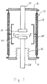
- An evacuated vessel 10 has an insulating cylinder 12, and a pair of end plates 14 and 16. The end plates 14 and 16 are tightly sealed to the opposite ends of the cylinder 12. A pair of separable electrodes 18 and 20 are arranged to penetrate the end plates 14 and 16. One electrode 18 is supported by a stationary rod 22 extending through the end plate 14, while the other electrode 20 is connected to a movable rod 24 which extends through the end plate 16 through a bellows 26.
- An arc shield 28 is provided in the evacuated vessel 10 to surround the electrodes 18 and 20 to prevent metal vapor generated by the electrodes 18 and 20 at the time of separation thereof from depositing on the inner surface of the evacuated vessel 10. An arc takes place between the two electrodes 18 and 20, when they are separated and the current is interrupted.
- Electrode 20 is of the so-called longitudinal magnetic field electrode construction in which a magnetic field in a direction parallel with the arc is generated as disclosed in U.S. Pat. No. 4,367,382.
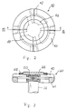
- the electrode 20 has a circular arc plate 40 which is arranged perpendicular to the direction of the arc.
- the arc plate 40 is made of electroconductive material such as copper, and has four radial slits 42.
- a coil member 44 is provided at the rear surface of the arc plate 40.
- the coil member 44 is made of electroconductive material such as copper, and creates a magnetic field in a direction parallel with the arc.
- a contact plate 46 is fixed on the center of the arc plate 40.
- the contact plate 46 is a circular flat plate of a smaller diameter than that of the arc plate 40.
- the contact plate 46 is made of low surge silver alloy, preferably an Ag-WC sintered alloy. The outer surface of the contact plate 46 projects out from the arc plate 40 toward the other electrode 18.
- a ring 48 made of silver is arranged on the arc plate 40 surrounding and adjacent to the contact plate 46.
- the outer surface of the ring 48 projects out from the arc plate 40 toward the other electrode 18.
- the height of the projection of the ring 48 is smaller than the contact plate 46.
- the arc plate 40 is supported by a reinforcing plate 50 made of nickel or stainless steel. It has high electrical resistance so that it does not affect the intensity of the magnetic field generated, and it prevents deformation or rupture of the arc plate 40 and the coil member 44 which might be caused by mechanical shocks at the time of closing of the circuit interrupter.
Landscapes
- High-Tension Arc-Extinguishing Switches Without Spraying Means (AREA)
- Arc-Extinguishing Devices That Are Switches (AREA)
Claims (8)
- Stromkreis-Unterbrecher, der aufweist:
ein Paar von Elektroden (18, 20), die relativ zueinander von einer Eingriffsposition in eine eingriffsfreie Position beweglich sind, um einen Stromkreisunterbrechungs-Lichtbogen zwischen den Elektroden zu erzeugen, wobei zumindest eine (20) der Elektroden (18, 20) eine Kontakteinrichtung (46) hat, die aus einem eine Silberlegierung einschließenden Material mit niedriger Überspannung besteht, und die der anderen Elektrode (18) gegenüberliegt, und eine Lichtbogenplatte (40) aus elektrisch leitendem Material mit einer silberbeschichteten Oberfläche hat, die der anderen Elektrode (18) gegenüberliegt und elektrisch mit der Kontakteinrichtung (46) verbunden ist,
und eine Einrichtung (10) zum Einschließen des Elektrodenpaares (18, 20) und zum Aufrechterhalten einer Vakuumatmosphäre um die Elektroden herum,
dadurch gekennzeichnet, daß ein Ring (48), der aus Silber besteht, so angeordnet ist, daß er die Kontakteinrichtung (46) umgibt und der anderen Elektrode (18) gegenüberliegt, wobei der Ring elektrisch mit der Kontakteinrichtung (46) verbunden ist. - Stromkreis-Unterbrecher nach Anspruch 1, worin die Kontakteinrichtung (46) von der Lichtbogenplatte (40) in Richtung der anderen Elektrode (18) hervorsteht.
- Stromkreis-Unterbrecher nach Anspruch 2, worin der Ring (48) von der Lichtbogenplatte (40) hervorsteht und die Kontakteinrichtung (46) von dem Ring in Richtung der anderen Elektrode (18) hervorsteht.
- Stromkreis-Unterbrecher gemäß einem der vorhergehenden Ansprüche, worin die Kontakteinrichtung (46) eine Ag-WC gesinterte Legierung aufweist.
- Stromkreis-Unterbrecher nach einem der vorhergehenden Ansprüche, worin die Lichtbogenplatte (40) im wesentlichen aus Kupfer besteht.
- Stromkreis-Unterbrecher nach einem der vorhergehenden Ansprüche, worin ein Außenabschnitt der silberbeschichteten Oberfläche der Lichtbogenplatte (40) den Ring (48) umgibt.
- Stromkreis-Unterbrecher nach einem der vorhergehenden Ansprüche, worin die Kontakteinrichtung (46) eine flache Platte ist.
- Stromkreis-Unterbrecher nach einem der vorhergehenden Ansprüche, worin die andere Elektrode (18) enthält:
eine zusätzliche Kontakteinrichtung, die aus einem eine Silberlegierung einschließenden Material mit niedriger Überspannung besteht, eine zusätzliche Lichtbogenplatte aus elektrisch leitendem Material, die eine silberbeschichtete Oberfläche hat und elektrisch mit der zusätzlichen Kontakteinrichtung verbunden ist, und einen zusätzlichen Ring, der aus Silber besteht und elektrisch mit der zusätzlichen Kontakteinrichtung verbunden ist.
Applications Claiming Priority (2)
| Application Number | Priority Date | Filing Date | Title |
|---|---|---|---|
| JP61250712A JPS63105419A (ja) | 1986-10-23 | 1986-10-23 | 真空バルブ |
| JP250712/86 | 1986-10-23 |
Publications (3)
| Publication Number | Publication Date |
|---|---|
| EP0264814A2 EP0264814A2 (de) | 1988-04-27 |
| EP0264814A3 EP0264814A3 (en) | 1989-03-15 |
| EP0264814B1 true EP0264814B1 (de) | 1993-06-09 |
Family
ID=17211929
Family Applications (1)
| Application Number | Title | Priority Date | Filing Date |
|---|---|---|---|
| EP87115035A Expired - Lifetime EP0264814B1 (de) | 1986-10-23 | 1987-10-14 | Vakuumschalter |
Country Status (6)
| Country | Link |
|---|---|
| US (1) | US4760223A (de) |
| EP (1) | EP0264814B1 (de) |
| JP (1) | JPS63105419A (de) |
| KR (1) | KR910001370B1 (de) |
| CN (1) | CN1006426B (de) |
| DE (1) | DE3786141T2 (de) |
Families Citing this family (6)
| Publication number | Priority date | Publication date | Assignee | Title |
|---|---|---|---|---|
| US5387771A (en) * | 1993-04-08 | 1995-02-07 | Joslyn Hi-Voltage Corporation | Axial magnetic field high voltage vacuum interrupter |
| US5793008A (en) * | 1996-11-01 | 1998-08-11 | Eaton Corporation | Vacuum interrupter with arc diffusing contact design |
| GB2338111B (en) * | 1999-02-02 | 2001-03-21 | Alstom Uk Ltd | Improvements relating to vacuum switching devices |
| KR100485245B1 (ko) * | 2002-10-22 | 2005-04-25 | 희성금속 주식회사 | 은과 텅스텐 카바이드 합금의 전기접점재료 |
| GB2508913A (en) * | 2012-12-14 | 2014-06-18 | Leslie Thomas Falkingham | Vacuum switch contact assembly |
| JP2023090342A (ja) * | 2021-12-17 | 2023-06-29 | 株式会社東芝 | 真空バルブ |
Family Cites Families (7)
| Publication number | Priority date | Publication date | Assignee | Title |
|---|---|---|---|---|
| DD77009A (de) * | ||||
| US3182156A (en) * | 1961-09-19 | 1965-05-04 | Gen Electric | Vacuum-type circuit interrupter |
| US3576960A (en) * | 1968-03-08 | 1971-05-04 | Gen Electric | Flange fastening means for a contact button for a vacuum-type circuit interrupter |
| DE2014638A1 (de) * | 1970-03-26 | 1971-10-14 | Siemens Ag | Verfahren zur Herstellung eines Zweischichten Kontaktstuckes |
| GB2050060B (en) * | 1979-05-22 | 1983-05-18 | Tokyo Shibaura Electric Co | Vacuum switches |
| JPS59163726A (ja) * | 1983-03-04 | 1984-09-14 | 株式会社日立製作所 | 真空しや断器 |
| JPH061655B2 (ja) * | 1984-05-18 | 1994-01-05 | 株式会社東芝 | 真空しや断器 |
-
1986
- 1986-10-23 JP JP61250712A patent/JPS63105419A/ja active Pending
-
1987
- 1987-10-14 DE DE87115035T patent/DE3786141T2/de not_active Expired - Fee Related
- 1987-10-14 EP EP87115035A patent/EP0264814B1/de not_active Expired - Lifetime
- 1987-10-14 US US07/108,125 patent/US4760223A/en not_active Expired - Fee Related
- 1987-10-22 KR KR1019870011712A patent/KR910001370B1/ko not_active Expired
- 1987-10-23 CN CN87107122A patent/CN1006426B/zh not_active Expired
Also Published As
| Publication number | Publication date |
|---|---|
| CN1006426B (zh) | 1990-01-10 |
| KR910001370B1 (ko) | 1991-03-04 |
| EP0264814A2 (de) | 1988-04-27 |
| DE3786141D1 (de) | 1993-07-15 |
| KR880005644A (ko) | 1988-06-29 |
| US4760223A (en) | 1988-07-26 |
| EP0264814A3 (en) | 1989-03-15 |
| CN87107122A (zh) | 1988-05-11 |
| DE3786141T2 (de) | 1993-11-11 |
| JPS63105419A (ja) | 1988-05-10 |
Similar Documents
| Publication | Publication Date | Title |
|---|---|---|
| EP0329410B1 (de) | Vakuumschalter | |
| US3163734A (en) | Vacuum-type circuit interrupter with improved vapor-condensing shielding | |
| EP0204262B1 (de) | Vakuumschalter | |
| US3185800A (en) | Vacuum type circuit interrupter with improved vapor-condensing shielding | |
| US3818164A (en) | Vacuum type electric circuit breaker | |
| JPS58145035A (ja) | 真空ア−ク放電装置 | |
| EP0264814B1 (de) | Vakuumschalter | |
| EP0076659B1 (de) | Vakuumschalter | |
| KR920006060B1 (ko) | 진공스위치관 | |
| CA1319731C (en) | Vacuum circuit interrupter with axial magnetic arc transfer mechanism | |
| EP0185211B2 (de) | Vakuumschalter | |
| US4501941A (en) | Vacuum interrupter contact material | |
| US4216360A (en) | Low voltage vacuum switch with internal arcing shield | |
| US4430536A (en) | Vacuum interrupter | |
| US3283101A (en) | Double-break vacuum switch with bellows mounted movable bridging contact | |
| US4661665A (en) | Vacuum interrupter and method of modifying a vacuum interrupter | |
| US4798921A (en) | Vacuum circuit breaker | |
| US3612795A (en) | Shielding arrangements for vacuum-type circuit interrupters of the two-contact type | |
| CA1187918A (en) | Unitary end closure and seal shield member for vacuum interrupter | |
| US4553003A (en) | Cup type vacuum interrupter contact | |
| US4797522A (en) | Vacuum-type circuit interrupter | |
| US4128748A (en) | High-current vacuum switch with reduced contact erosion | |
| US3849617A (en) | Constriction type vacuum interrupter | |
| US4072837A (en) | High continuous current vacuum-type circuit interrupter | |
| GB2188487A (en) | Arcing electrode for switch |
Legal Events
| Date | Code | Title | Description |
|---|---|---|---|
| PUAI | Public reference made under article 153(3) epc to a published international application that has entered the european phase |
Free format text: ORIGINAL CODE: 0009012 |
|
| AK | Designated contracting states |
Kind code of ref document: A2 Designated state(s): DE GB |
|
| PUAL | Search report despatched |
Free format text: ORIGINAL CODE: 0009013 |
|
| AK | Designated contracting states |
Kind code of ref document: A3 Designated state(s): DE GB |
|
| 17P | Request for examination filed |
Effective date: 19890828 |
|
| 17Q | First examination report despatched |
Effective date: 19911122 |
|
| GRAA | (expected) grant |
Free format text: ORIGINAL CODE: 0009210 |
|
| AK | Designated contracting states |
Kind code of ref document: B1 Designated state(s): DE GB |
|
| REF | Corresponds to: |
Ref document number: 3786141 Country of ref document: DE Date of ref document: 19930715 |
|
| PLBE | No opposition filed within time limit |
Free format text: ORIGINAL CODE: 0009261 |
|
| STAA | Information on the status of an ep patent application or granted ep patent |
Free format text: STATUS: NO OPPOSITION FILED WITHIN TIME LIMIT |
|
| 26N | No opposition filed | ||
| PGFP | Annual fee paid to national office [announced via postgrant information from national office to epo] |
Ref country code: GB Payment date: 19961007 Year of fee payment: 10 |
|
| PGFP | Annual fee paid to national office [announced via postgrant information from national office to epo] |
Ref country code: DE Payment date: 19961018 Year of fee payment: 10 |
|
| PG25 | Lapsed in a contracting state [announced via postgrant information from national office to epo] |
Ref country code: GB Free format text: LAPSE BECAUSE OF NON-PAYMENT OF DUE FEES Effective date: 19971014 |
|
| GBPC | Gb: european patent ceased through non-payment of renewal fee |
Effective date: 19971014 |
|
| PG25 | Lapsed in a contracting state [announced via postgrant information from national office to epo] |
Ref country code: DE Free format text: LAPSE BECAUSE OF NON-PAYMENT OF DUE FEES Effective date: 19980701 |