EP0264532B1 - Accumulating conveyor with self-propelled pallets - Google Patents
Accumulating conveyor with self-propelled pallets Download PDFInfo
- Publication number
- EP0264532B1 EP0264532B1 EP87106417A EP87106417A EP0264532B1 EP 0264532 B1 EP0264532 B1 EP 0264532B1 EP 87106417 A EP87106417 A EP 87106417A EP 87106417 A EP87106417 A EP 87106417A EP 0264532 B1 EP0264532 B1 EP 0264532B1
- Authority
- EP
- European Patent Office
- Prior art keywords
- pallet
- pallets
- track
- station
- drive motor
- Prior art date
- Legal status (The legal status is an assumption and is not a legal conclusion. Google has not performed a legal analysis and makes no representation as to the accuracy of the status listed.)
- Expired - Lifetime
Links
Images


Classifications
-
- B—PERFORMING OPERATIONS; TRANSPORTING
- B65—CONVEYING; PACKING; STORING; HANDLING THIN OR FILAMENTARY MATERIAL
- B65G—TRANSPORT OR STORAGE DEVICES, e.g. CONVEYORS FOR LOADING OR TIPPING, SHOP CONVEYOR SYSTEMS OR PNEUMATIC TUBE CONVEYORS
- B65G35/00—Mechanical conveyors not otherwise provided for
- B65G35/06—Mechanical conveyors not otherwise provided for comprising a load-carrier moving along a path, e.g. a closed path, and adapted to be engaged by any one of a series of traction elements spaced along the path
-
- B—PERFORMING OPERATIONS; TRANSPORTING
- B23—MACHINE TOOLS; METAL-WORKING NOT OTHERWISE PROVIDED FOR
- B23Q—DETAILS, COMPONENTS, OR ACCESSORIES FOR MACHINE TOOLS, e.g. ARRANGEMENTS FOR COPYING OR CONTROLLING; MACHINE TOOLS IN GENERAL CHARACTERISED BY THE CONSTRUCTION OF PARTICULAR DETAILS OR COMPONENTS; COMBINATIONS OR ASSOCIATIONS OF METAL-WORKING MACHINES, NOT DIRECTED TO A PARTICULAR RESULT
- B23Q7/00—Arrangements for handling work specially combined with or arranged in, or specially adapted for use in connection with, machine tools, e.g. for conveying, loading, positioning, discharging, sorting
- B23Q7/14—Arrangements for handling work specially combined with or arranged in, or specially adapted for use in connection with, machine tools, e.g. for conveying, loading, positioning, discharging, sorting co-ordinated in production lines
- B23Q7/1426—Arrangements for handling work specially combined with or arranged in, or specially adapted for use in connection with, machine tools, e.g. for conveying, loading, positioning, discharging, sorting co-ordinated in production lines with work holders not rigidly fixed to the transport devices
- B23Q7/1436—Arrangements for handling work specially combined with or arranged in, or specially adapted for use in connection with, machine tools, e.g. for conveying, loading, positioning, discharging, sorting co-ordinated in production lines with work holders not rigidly fixed to the transport devices using self-propelled work holders
Definitions
- This invention concerns an accumulating conveyor according to the generic part of claim 1.
- Synchronous transfer devices such as shuttles and lift and carry devices have long been used in which a series of workpieces are each simultaneously advanced between stations in step-by-step fashion.
- Nonsynchronous devices have also been employed in which the workpieces are each transferred independently of the movement of the other workpieces. Examples of these include power roller and "delmatic" conveyors. Arrangements are known in which pallets are individually controlled to be clutched and declutched to a conveyor chain to establish independent advance of each pallet and allow accumulation of pallets upstream of each workstation. See U S-E- 25,886 for an example of such accumulation of chain driven pallets upstream of each work station.
- Accumulation is a desirable feature, particularly in systems where various machine tools are tied together in an integrated manufacturing system.
- accumulation is meant the ability to allow a series of work pieces to wait in readiness upstream of a given work station to provide "float", avoiding interruption of production if the supply of workpieces is temporarily discontinued.
- Synchronous transfer devices require complex mechanical, electrical or pneumatic control components to provide an accumulation capability.
- An advantage of nonsynchronous conveyors is their ability to provide an accumulation feature without the need for such complex controls.
- nonsynchronous accumulating conveyors which have herefor been provided have utilized drive systems which have been custom engineered for each application and which involve interrelated drive components such that mechanical failure of any of these components tends to result in complete shutdown in the conveyor system as a whole, with the resultant loss of production of the entire manufacturing system.
- Such mechanical conveyor systems have also typically involved the use of complex mechanical components.
- U S -A- 4,015,537 discloses the use of bumper switches used for discontinuing drive of a car upon encountering obstruction. Such obstruction detection is not disclosed as utilized in the normal functioning of the system and also is described as preferably being arranged for both the front and rear of each car, which would render the system impractical for application to accumulating conveyor systems, particularly for manufacturing.
- the touching contact required to trigger the bumper switch and stop the car does not allow for sufficient positional accuracy of the car in the stopped position for many of the applications in automated handling of workpieces.
- Each of US-A-4,015,537 and US-A-4,056,063 contemplates complex electrical controls for the directing of cars to a particular station.
- U S -E- 25,886 also discloses a mechanical sensing of a next adjacent pallet, and declutching from a conveyor drive chain, as does U S -A- 4,461,216 and U S-A- 4,338,864.
- U S -A- 4,461,216 also discloses vertically spaced runs of an accumulating conveyor, allowing return of pallets beneath an upper run, with pusher dogs deactivated by sensing of another pallet ahead to enable accumulation in both directions.
- the nature of the drive involves complex mechanical drive components.
- U S-A- 4,552,260 describes an over and under synchronous transfer of pallets, with lift mechanisms at either end of the upper and lower conveyor runs, which arrangement also involves complex mechanical drive components.
- DE-A-3 309 335 refers to light rays and reflective areas to prevent bouncing of the pallets when one of them is stopped e.g. in a waiting position in front of a station.
- the problem to be solved by the invention is to provide a readiness control allowing entry of the next pallet into a work station only when the station is ready to accept it.
- each of the pallets carries a simple, self contained, electrical control system with a minimum of interaction with the electrical controls of the conveyor system as a whole.
- These controls comprise proximity sensing means, preferably a non contacting sensing means such as a photo electric switch, disposed at the leading end of each pallet carrier, which sensing means detects the approach of the pallet to the next adjacent pallet forward of each carrier, and causes the propelling drive of the carrier to be discontinued to bring the pallet to a stop.
- proximity sensing means preferably a non contacting sensing means such as a photo electric switch, disposed at the leading end of each pallet carrier, which sensing means detects the approach of the pallet to the next adjacent pallet forward of each carrier, and causes the propelling drive of the carrier to be discontinued to bring the pallet to a stop.
- On board control over the propulsion of each pallet is utilized to achieve an accumulation of work carriers upstream of each work station when an excess number of pallets are included in the system, such that queuing of a supply of workpieces upstream of each work station results, each pallet moving up automatically as the next ahead pallet moves forward.
- the non-contacting switches also provide a simplified control over the propelling of each pallet into a work station, by controllably positioning one or more movable barrier members at each station.
- the presence of the barrier member provides a readiness control, allowing entry of the next pallet only when the readiness barrier member is positioned out of the path of the next pallet, and the station is ready to accept the next pallet.
- the readiness barrier members function as fail safe stops to restrain propulsion of a given pallet past the barrier in the event the electrical control fails.
- An alarm may be incorporated responsive to malfunction and cessation of pallet movement for a predetermined time period to provide a visual or audible indication of the failed electrical controls.
- the pallets are propelled by drive motors carried on the pallets which are powered by a battery carried on each pallet, and which battery is recharged during the queuing interval of the cycle of operation, by means of charging conductor bars positioned on either side of the conveyor track immediately upstream of one or more of the work stations.
- the conductor bars are engaged by spring loaded contacts carried on each pallet with the conductors being connected to a suitable charging electrical power source, such that the waiting interval prior to entry into a station is employed to maintain the batteries in a fully charged condition.
- the conveyor system is utilized for transporting workpieces between load and unload stations at either end of the conveyor system.
- a feed and return track arrangement is incorporated, in which a feed main track is spaced from a second or return main track.
- an elevator mechanism is provided at both the load and unload stations at either end of the conveyor system.
- each of the pallet carriers is provided with a "forward" and “rearward” proximity sensor device, and the pallet drive motor is reversed to drive the pallet in a reverse direction along either of the vertically spaced tracks, with the forward and rearward sensors only activated when the pallet is driven in the respective directions.
- the invention has the advantage of greater reliability and easier maintanence than conventional mechanically driven accumulating conveyors since each of the pallets is self contained and able to be lifted out of the system for maintenance or for other purposes without any effect on the operation of the conveyor system as a whole.
- the invention also may be lower in cost and is easily reworked into different configuration since the conveyor system requires only standardized straight and curved track sections, which may be repositioned to reconfigure the conveyor system as required in order to be adapted to changed requirements.
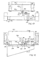
- FIGURE 1 is a fragmentary diagrammatic plan view of a conveyor according to the present invention.
- FIGURE 1A shows a diagrammatic representation of an alternate form of the pallet incorporated in the conveyor system of Figure 1.
- FIGURE 2 is a diagrammatic side elevational view of a particular application of the conveyor system according to the present invention to loading and unloading of workpieces at spaced stations.
- FIGURE 3 is a bottom view of a self propelled pallet utilized in the conveyor system according to the present invention.
- FIGURE 4 is a view of the section 4-4 taken through the propelled pallet shown in Figure 3.
- FIGURE 5 is a view of the section 5-5 taken through the pallet shown in Figure 3.
- FIGURE 6 is a view of the section 6-6 taken through the pallet shown in Figure 3.
- FIGURE 7 is a view of the section 7-7 taken through the pallet shown in Figure 3.
- FIGURE 8 is a view of the section 8-8 taken through the pallet shown in Figure 3.
- FIGURE 9 is a schematic diagram of the on-board electrical control system incorporated in the self propelled pallet shown in Figures 3 and 4.
- FIGURE 10 is a cross sectional view of a two level track incorporated in the conveyor depicted in Figure 2.
- FIGURE 11 is a fragmentary side-elevational view of the two level track shown in Figure 10 illustrating the joinder of adjacent track sections.
- FIGURE 12 is a fragmentary view of the pallet showing adjacent track sections illustrating the engagement of a wiper contact with a conductor bar during charging of the power battery incorporated in the pallet of Figures 3-8.
- FIGURE 13 is a view of a section of track with the conductor bar installed thereon and illustrating the engagement action occurring as a pallet advances to cause engagement of the spring loaded contacts with the charging conductor bar.
- FIGURE 14 is a elevational view of a lift-lower mechanism incorporated in the conveyor system depicted in Figure 2.
- FIGURE 15 is a view of the section 15-15 taken in Figure 14.
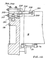
- FIGURE 16 is a fragmentary view of a portion of the lift and lower mechanism depicting the readiness barrier member movement.
- FIGURE 17 is a fragmentary sectional view of section 17-17 taken in Figure 14.
- FIGURE 18 is a fragmentary elevational view of a locator clamp assembly incorporated at a station in the conveyor system according to the present invention.
- FIGURE 19 is a fragmentary plan view of the locator clamp assembly shown in Figure 18.
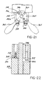
- FIGURE 20 is a front elevational view of a manually operated movable locator barrier member assembly installed along a conveyor track.
- FIGURE 21 is an end view of the assembly shown in Figure 20.
- FIGURE 22 is a view of the section 22-22 taken in Figure 21.
- FIGURE 1 depicts the basic operating concept of the nonsynchronous accumulating conveyor 10 according to the concept of the present invention which includes a conveyor structure 12 extending successively to a first station 14 and then in sequence to a second station 16, with operations performed on workpieces at each station 14 and 16.
- the workpieces (W) are mounted to be fixturized and carried on a series of self-propelled pallets 18 which are positioned on a upper or lower track 20 included in the conveyor structure 12 extending along the length thereof.
- the propulsion of the pallets 18 along the tracks is accomplished by means of an electric drive motor 22 carried by each pallet 18.
- the motor 22 when energized causes drive of a drive element such as a roller or wheel (not shown) supporting the pallet 18 on the track 20.
- the energization of the motor 22 and the consequent propulsion of the self propelled pallet 18 is controlled by means of a proximity sensor device 24 such as a photoelectric non-contacting switch which detects the proximity of a structure immediately ahead of the pallet 18 in the direction of propulsion, causing a de-energization of the propelling motor 22.
- a proximity sensor 24 acting through an onboard control circuit 26, acts to de-energize the motor 22, quickly bringing the pallet 18 to a stop, with dynamic braking or internal friction of the motor 22 or gearing aiding in this process.
- an excess number of pallets 18 are utilized over the number of stations, so that a stackup or accumulation of pallets 18 ahead of each station 14 and 16, is provided, with the pallets 18 queuing one behind the other upon sensing the presence of the next adjacent pallet in the series.
- the proximity sensor device 24 is utilized to control the entry of each pallet successively into a station 14 and 16 and also may be utilized to approximate the positioning of each pallet 18 within the station 14 or 16.
- the readiness barrier member 28 is moved into position in the path of the pallets 18, which causes the first pallet 18B just ahead of station 14 to cease to be propelled, and come to rest at a location just upstream of the station 14 as shown, by sensing of the readiness barrier member 28 by the respective proximity sensor device 24.
- the pallet 18B Upon removal of the barrier member 28 out of the path of the next pallet 18B, the pallet 18B is again begun to be propelled by energization of the drive motor 22 such as to move into the station 14 on tracks 28 located within the station 14.
- the pallet 18A shown within station 14 was brought to rest in the proper location within the station 14 by means of a "locator" barrier member 30 positioned in the path of the pallet 18B. Upon sensing of the locator barrier member 30, the drive motor 22 is again de-energized and the pallet 18 brought to rest in the proper location within the station 14.
- the pallet 18 Upon completion of operations in station 14 on the workpiece W, the pallet 18 is again energized so as to be propelled out of the station 14 onto the parallel tracks 20 to proceed to the next station 16. Again, a sufficient number of pallets 18 are provided in the system such that a queuing is likewise formed upstream of the number 2 station 16, to thereby provide a "float" in the system. That is, to provide an accumulating effect, since each car will successively move into the station with the cars to the rear moving up as the next adjacent forwardly located pallet 18 moves away therefrom to allow re-energization of each of their respective propulsion drive motor 22.
- this relatively simple control system does not require substantial interreaction between the pallets 18 and the remaining elements of the conveyor system 10 with only the movable barrier members 28 and 30 required to achieve a nonsynchronous accumulating conveyor. Any malfunction in the individual pallets 18 or removal of an individual pallet for repair or maintenance will not affect the operation of the conveyor system 10 as a whole.
- FIGURE 1A shows further details of the pallets 18 according to the preferred embodiment in which the drive motor 22 is driven by an onboard power source comprised of a rechargable battery 32.
- the rechargable battery 32 of each pallet 18 is charged while the pallet 18 is queued in line ahead of one or more of the stations 14 or 16 such that the delay interval inherent in the accumulating mode may be utilized to maintain the rechargable battery 32 in a fully charged condition such as to avoid any need for special handling of the pallets in the conveyor system to accomplish recharging of a batteries 32.
- Conductor charging bars 34 are positioned immediately upstream of the station 14 and spring loaded contacts 36 are carried on either side of the pallet 18 which move into engagement with the conductor strip 34 as the particular pallet 18 is propelled into the region immediately upstream of the station 14.
- a charging electrical power source 38 of appropriate polarity is associated with each conductor bar 34.
- each self propelled pallet 18 may in some cases be accomplished entirely by means of the proximity sensor devices 24, an electrical control is also contemplated in which a pair of photo electric switches 40A and 40B are mounted on the side of each pallet 18, with corresponding pairs of photo emitting devices 42a and 42b positioned on the conveyor structure 12 to come into registry with a respective photoelectric switch 40A or 40B at locations whereat it is desired to bring the pallet 18 to a stop.
- This control is preferred over the use of a locator barrier member 30 where differences in reflectivity between the locator barrier members 30 and pallets 18 are likely to occur due to accumulations of dirt, as is likely in typical factory environment.
- the on-board pallet controls 26 react to excitation of the photo electric switches 40A, 40B to cause the drive motor 22 to be de-energized and bring the particular pallet 18 to a stop.
- the pallet 18 is moving at a much slower speed and able to respond more reliably and brought to a stop in an accurately and controlled position.
- the present conveyor system can also be utilized where workpieces are transported between load and unload stations where other work handling devices are employed to move workpieces into machine tools or other manufacturing apparatus.
- the conveyor system 10 is in this instance employed purely for transport of the work pieces between the load and unload locations and interaction with handling of robots or other workhandling devices.
- FIGURE 2 illustrates such an application diagrammatically in which the first station 14 is a load station whereat a loading mechanism such as a robot 44 acts to load workpieces onto the pallets 18, which are then propelled down an upper track 20A to an unload station 16 where a second unloader, robot 46, removes workpieces (W) from the pallets 18.
- a loading mechanism such as a robot 44 acts to load workpieces onto the pallets 18, which are then propelled down an upper track 20A to an unload station 16 where a second unloader, robot 46, removes workpieces (W) from the pallets 18.
- a lower return track 20B is provided with a lift-lower mechanism 48 provided in load station 14.
- a lift-lower mechanism 50 is also provided at the unload station 16.
- the pallets 18 are driven alternatively in opposite directions and therefore are provided with a pair of non-contacting switches 24A each located at either end of the pallet 18, which alternatively cause de-energization of the motor 22 upon approach of either end of the pallet 18 to a structure in the path of the pallet 18 when being propelled so as to position the particular switch 24A or 24B at the leading end of the pallet 18.
- each pallet 18 in this embodiment is reversible to produce propulsion of the pallet 18 in opposite directions.
- the pallets 18 are each able to be driven in one direction on the upper track 20A, and in another direction on the lower track 20B, after being lowered in the same orientation to the track 20B by means of lift-lower mechanism 50.
- Emitter devices 52A and 52B are provided, one at each station 14 and 16, activated by the machine controls which activate photo electric switches 54A or 54B respectively on the side of each pallet 18.
- the onboard pallet control circuit 26 causes reversal of the electric propulsion motor 22 to be energized in either the forward or rear direction, to propel each pallet 18 out of either the lift-lower mechanism 48 or 50 and to proceed out from either station 14 or 16 in the reverse direction from which it entered that station.
- Auxiliary rails 56 of each of the lift-lower mechanisms 48 and 50 receive each pallet 18 successively, entry thereon being controlled by a movable readiness barrier member 28, moved into position only upon proper positioning of a rails 56 with either upper track 20A or lower track 20B respectively.
- Slow speed and stop photoelectric switches 40A and 40B, and associated photo emitter devices 42A, 42B are contemplated as bringing each pallet 18 to a stop at the proper location on the auxiliary rails 56.
- each lift-lower mechanism is also provided in each lift-lower mechanism.
- a safety barrier member 30 which may be attached to the auxiliary rails 56, creating a physical barrier to prevent propulsion of the pallets 18 out of the station in the event the controls fail.
- the particular pallet 18 is driven onto the auxiliary track 56 and is continued to be driven until switches 40A and 40B moving into registry with photo emitter 42A or B at which time the drive motor 22 is slowed and then de-energized to bring the pallet 18 to a stop on the auxiliary rails 56.
- the rails 56 are then elevated by a suitable mechanism, such as a pneumatic cylinder to be described, to raise the pallet 18 so that the auxiliary rails 56 are brought to the level of the upper track 20A.
- photo emitter device 52B moves into alignment with a forward photo electric switch 54B (as does switch 40B and emitter device 42B, not shown).
- the machine controls 25 cause energization of emitter devices 42B and 52B, causing energization and reversal of the drive motor 22, the pallet 18 is immediately propelled off of the auxiliary rail 56 and onto the upper track 20A, and to proceed down to the unload station 16 after completion of the unload operation lowering of the auxiliary rails 56.
- loading robots 44 and 46 are normally controlled by a machine control 25 to seek a part at a precise location in the respective station.
- the robot 44 or 46 not finding a part at the proper location are typically simply shut down by the machine controls 25.
- This condition may trigger an alarm 23 by incorporating a timer 21, which is triggered after a predetermined period when no further movement of pallets 18 occurs due to the shut down of a robot 44 or 46. This will alert an operator of a malfunction in the conveyor system 10.
- the number of pallets 18 provided is sufficiently greater than the number of stations, such that accumulation is achieved by the queuing up of a number of pallets 18 upstream of each station 14, 16.
- FIGURE 3 depicts the details of a pallet 18 according to the present invention, which includes a sheet metal housing 58 defining a substantially rectangular box, for housing the components of the pallet 18.
- a bottom plate 60 is shown in fragmentary form, provided to insure protection of the internal components from the environment, with a section thereof hinged at 61 to allow convenient access to the interior thereof.
- Rubber bumpers 62 may be provided on the ends of the pallet 18 to reduce the force of contact in the event of accidental impacting of the pallets 18.
- Each pallet 18 carries hardened steel roller wheel assemblies 64 and 66 spaced apart on one side of the pallet 18 and a third roller assembly 68 centered therebetween on the opposite side.
- Edge guiding roller assemblies 70 and 72 are provided adjacent roller assemblies 64 and 66 having opposing pairs of roller elements 74 and 76 mounted onto yoke member 78 adapted to engage either edge of the spaced parallel members forming the tracks 20 (not shown in Figure 3).
- roller 65 included in roller assembly 64 is adapted to be driven so as to cause the propulsion of the pallet 18 by means of the electric drive motor 22, also mounted within housing 58 by bracket 89.
- Drive motor 22 preferably is of a reversible DC type, having an output shaft 88 connected by a coupling 90 to a gear reduction-right angle drive unit 92 having a drive output shaft 91 connected to rotate the roller 65 of roller assembly 64 by set screws 67 received in threaded bores 69 of roller 65.
- the roller 65 is thereby driven by motor 22 at a greatly reduced rate of rotation, a 30:1 reduction for a typical application.
- Suitable reversible DC motors, couplings and gear reducer-right angle drive units are commercially available, and accordingly a detailed description is not here set forth.
- a rechargable battery 32 mounted in a sheet metal housing 94 is a rechargable battery 32 adapted to provide power for the electrical drive motor 22, with terminals 21 allowing connection to the control circuit 26.
- a rechargable battery 32 is of the so called “gel cell” configuration commercially available under the tradename “Globe Gel Cell Battery", Model no. U-128-HD, 12V, in order to allow hoisting and handling of the pallets 18 in various attitudes without danger of spilling the electrolyte solution from within the battery 32.
- Fore and aft proximity sensors are provided comprised of a forward non contacting photoelectric switch 24A, of a type commercially available, providing for opening of normally closed contacts upon receiving a predetermined level of diffuse reflectance of an emitted beam from an adjacent surface.
- a window 96 protrudes from the pallet housing 58 to enable receiving of reflected light by beam switch 24A.
- Such reflectance photoelectric switches are commercially available, for example the Cutler Hammer Diffuse Reflective Beam Switch Model No. E 65 VNL 2.
- a rear non contacting proximity switch 24B is provided, which may also be comprised of a diffuse reflectance beam switch of the type utilized on the forward end of the pallet 18, receiving reflected emmissions through a protruding window 96 on the rear side of the housing 58.
- Switches 24A and 24B have normally closed contacts which will be opened upon approach of the pallet within a predetermined distance, in the series as described above.
- a vertically aligned series of photoelectric receiver switches 54A, 40A, 40B, while on the same side but spaced at the other end of the pallet 18 is the other reversing switch 54B.
- a protruding window 98 is exposed on each to enable reception of a beam from emitter devices 42A, 42B, 52A, 52B as shown in Figure 2.
- These switches may be provided by Cutler Hammer Beam Receivers Model No. E6SVNL3.
- proximity sensor devices such as reed switches may be used where design criteria allow the operating characteristics of such components to satisfy the requirements of a particular application, but the optical switches are preferred for this application.
- the components of the on board pallet control circuit 26 are mounted on a circuit board 101, protected within a cover 102, which control circuit 26 includes miniature relays electrically connected to forward and rear proximity switches 24A and 24B, as well as to slowing, reversing and stopping photo electric switches 54A, 54B, 42A, 42B to control the drive motor 22.
- a pair of contact assemblies 36 is also depicted in Figure 3, mounted to the lower left hand corner of the pallet housing unit 18 as viewed in Figure 3.
- the contact 108 protrudes sufficiently to cause engagement with a respective conductive bar 34 to occur as the pallet 18 moves alongside, as will be described hereinafter.
- a pair of hardened steel locator plates 332 are affixed to each end of the housing 58 on the top side as viewed in Figure 3, cooperating with a mechanical clamping mechanism as will be described hereinafter.
- FIGURE 4 illustrates that the pallet housing 58 has an aluminum plate 110, positioned atop a flange portion 112 of the housing 58. Fixturing (not shown) locates and mounts a workpiece (W) on the upper surface thereof.
- the bottom cover plate 60 is positioned against a bottom flange 63 of housing 58.
- the switches 40A, 40B, 54A are vertically aligned and fastened with screws 57 passing through the housing 58.
- the other switches 24A, 24B, 54B are similarly mounted.
- the battery housing 94 is attached to the underside of fixture plate 110 with screws 95 passing through a cover flanges 97.
- Edge roller assembly 72 includes a pair of opposed rollers 71 rotatably mounted on pins 13 received in yoke member 72.
- FIGURE 5 illustrates the mounting of each roller 65 in roller assemblies 64, 66, 68 onto a roller pedestal 65A, in turn mounted to the underside of plate 110 with screws 65B.
- An axle bolt 65C passes through a hub ball bearings 65D and pedestal 65A to rotatably support the roller 65 thereon, with a nut 65E returning the same.
- Each roller 65 is comprised of a polyurethane wheel 65 pressed onto aluminum rims 65F. This provides for low wear running contact on tracks 20, and the resilient nature of the polyurethane accommodates chips and other debris on the tracks 20.
- rollers 65 of roller assemblies 64, 66, 68 run on the upper surface 114 of the tracks 20, while the side guiding roller pairs 76, 74 straddle the edges to provide a mechanical guiding of the pallet 18 on the tracks 20 for accurate location side-to-side of the pallet 18 along the length of the conveyor structure 12.
- FIGURE 6 illustrates the fastening of the fixture plate 110 to flanges 112 with screws 113; and the mounted bottom cover plate 60 to flange 63 with screw fasteners 115 received in threaded receptacles 117 of a well known type.
- FIGURE 7 shows the securing of battery cover 91 included in battery housing 94 with screws 85 received in receptacles 87.
- FIGURE 8 illustrates details of the spring loaded contact assembly 36 which include a housing 220 comprised of a molded plastic box 222, and a bottom cover 224, secured together against a side wall of the housing 58 of pallet 18 by means of a nut and bolt assembly 226.
- the housing 220 defines a cavity 228 in which is disposed the spring loaded contact 108 having a 30 protruding chaufered end blade portion 110 and a spring engagement socket 230 at the rear face thereof activated by a compression spring 232 received over a respective guide post 234 pressed into end cap 224.
- a suitable electrical lead (not shown) provides a connection to the battery 32.
- FIGURE 9 is an electrical schematic diagram of the typical electrical control circuit 26 included in each pallet 18.
- the rechargable battery 32 as previously indicated is preferably of a "gel cell” design, 12 volts DC, and has the negative terminal connected to ground, and the positive terminal to fuse F1, via lead 118 with an on-off main switch 122 disposed in line 124, to control application of battery voltage to the main line 120.
- the battery 32 is adapted to be recharged via lines 126 and 128 connected to contacts 108, in turn connected to an 18v dc voltage source (not shown).
- a commercially available voltage regulator chip VR1 104 also is connected such as to control the voltage applied to charge the battery 32 with an applied voltage of capacitive filters C1 ADC 2 preventing spikes and drode D1 preventing shorting of the contacts 108.
- a suitable chip 104 is model ECG934, IC-POS VR, 3 Terminal 13-8 V, SAMP.
- a "low battery” LED D2 is included to detect a low voltage condition of the battery which is preferably mounted externally of the housing 58 to provide a visual indication of the condition.
- LED D2 is activated by a bridge circuit 104, connected via lead 121 to main line 120.
- Bridge circuit 104 is of a well known design including resistors R2, R3, R4 and operational amplifier IC1 so as to trigger LED D2 when a low (10 volt) level is detected, causing a triggering current to fire LED D2 via current limiting resistor R1.
- the forward and rear non contacting switches 24A and 24B have their contacts connected by socket 52 and pin 52 to lines 130 and 132, and are normally closed as shown until a reflected photo signal received from adjacent structures reaches an intensity level such as to cause the switch contacts to open, this denergizes the drive motor 22 depending on which of the non contacting switches 24A or 24B is operatively effective in the control circuit 26.
- This result is controlled by normally open contacts 136 of a latching relay CR4, 134, closed by activation of photo switch 54A, placing the branch line 132 into the circuit, opening the contacts 138 to remove the proximity sensor device 24B from the circuit.
- Latching relay CR4 134 is latched by energization of a photo switch 54A located at the elevated position of the elevator 50 in the embodiment shown in Figure 2.
- Normally closed contacts 140 of relay CR3 142 allow energization of relay CR1 144, unless the normally open photoelectric switch 40B is closed by energization of the photo switch 54B. With energization of photo switch 54A and latching of CR4 134, contacts 136 are closed to energize relay CR1 144. At the same time contacts 146 of latching relay CR4 134 are closed to energize relay CR2 148. When relay CR1 144 is energized, normally open contacts 150 are closed.
- relay CR5 152 If the latching relay CR5 152 is unlatched, i.e., in the absence of activation of photoelectric switch 40A, the contacts 154 of relay CR5 152 are closed, such that branch line 156 is placed into the circuit, and since contacts 150 of CR1 144 are closed, branch line 158 is placed in the circuit. Since relay CR2 148 is energized, normally open contacts 160 thereof are closed to apply voltage to one side of the drive motor 22. Normally closed contacts of CR2 162 are opened upon activation of relay CR2 148. Normally open contacts 164 of relay CR2 148 are closed by the activation thereof such that the opposite side of drive motor 22 is connected via line 166 to thus energize the motor 22 and cause it to propel the pallet 18 in the forward direction.
- the non contacting switch 24A opens, opening the circuit across line 130 and thereby de-energizing drive motor 22.
- Closing of the photoelectric switch 54B also reverses the direction of rotation of the drive motor 22, by the unlatching of latching relay CR4 144.
- the normally open contacts 146 of relay CR4 134 are opened such that relay CR2 148 is de-energized, and thus normally closed contacts 162 of CR2 148 are closed, such that voltage is applied across branch line 166 to the opposite side of the motor 22.
- Relay contacts 174 of relay CR2 148 are closed to connect circuit ground to the other side of drive motor 22 such as to reverse polarity of the applied voltage to the drive motor 22, to reverse the drive of the pallet 18.
- Contacts 160 of CR2 148 are opened as are contacts 162 of CR2 148 to complete the reversal of polarity of the voltage applied to the drive motor 22.
- the reverse non contacting switch 24B Upon approaching a pallet 18 in the reverse direction the reverse non contacting switch 24B opens to de-energize relay CR1 144 and interrupt drive of the motor 22 as in the forward direction.
- Excitation of normally open photoelectric switch 40B energizes relay CR3 142 via line 133 and also unlatches latching relay CR5 152. This opens contacts 154 of Cr 5 152 and closes contacts 176. Energizing relay CR3 142 causes de-energization of relay CR1 144, opening contacts 150 thereof to de-energize motor 22.
- latching relay CR5 152 is unlatched via line 137, opening contact set 154 and closing contacts 156, placing a resistor R2 178 in the circuit, and reducing the applied voltage to drive motor 22 to thus reduce the speed of rotation thereof, preferably to a small fraction of the full speed drive i.e., approximately 10% speed .
- the latching relay CR5 152 is latched to again close contacts at 154, bypassing the resistor R2 178 from the circuit.
- a diode D4 may be connected across one or more of the relays to shunt transient currents created by rapid opening and closing of the relay, thereby eliminating unwanted triggering of other relays in the manner well known in the are.
- FIGURE 10 depicts in cross section the constructional details of the two level track conveyor system of the embodiment of FIGURE 2.
- the conveyor sections 12A and 12B are formed by identical pairs of channel extrusions 180, joined together by means of separate pieces 182 received beneath the lower surface channel 180 secured my means of T-bolts received in T-slots 184.
- the track sections 20A, 20B are comprised of steel angles mounted on the inside of a respective channel 180 by means of stand offs 186 secured by bolts received in T-slots 188 to correctly position the track sections 20A, 20B in parallel pairs.
- FIGURE 11 illustrates that vertical I-sections 190 position the conveyor sections 12A and 12B a proper distance apart and also may act to lock together adjacent conveyor sections 12A and 12B by the means of flanges 192 lapping the adjacent sections, with T-bolts 194 received in T-slots 196 in the upper face of the extruded channel 180.
- a support pedestal 198 and flange 200 mount one end of spliced conveyor sections 10, 12 on a floor surface with suitable hold down bolts and leveling screws 202 provided.
- a box beam portion 204 similarly enables splicing together of adjacent lower conveyor sections 12B.
- T-bolts 206 received in T-slots 208 provide securement of the under surface of each of the lower channels 180.
- T-slots 196 of the upper conveyor section 12A may be provided with molded trim strips 210, inserted in the T-slots 196.
- Each channel 180 is also provided with an upper recess 212 for mounting components on the inside intermediate space such as the conductive bars 34, as will be described below.
- the channels 180 define cavities 214 which are closed off by suitable plastic cover strips 216 received in upper slot 218 and lower slot 219 formed in the extruded channel 180, with the cavity 214 enabling mounting and protection of the switches, electrical cables, etc. while providing a trim exterior appearance.
- FIGURE 12 illustrates the engagement position of the contact 108 with one of the conductive bars 34.
- Each bar 34 is mounted in the recess by means of pedestals 242 received in recesses 212 cammed in the channel 180 located so as to be engaged by a contact 108 as the pallet 18 progresses into registry therewith.
- FIGURE 13 illustrates that each bar 34 is inclined in its forward end such that the contact 108, formed with ramping surfaces 244, is cammed against the bias of compression spring 232 as the pallet 18 progresses along the conveyor 10 such as to be brought into firm contact with the bar 34.
- FIGURES 14 and 15 illustrate some of the details of a lift-lower mechanisms 48, 50 for incorporation in the embodiment of Figure 2.
- the lift-lower mechanisms 48 and 50 include a frame 250 comprised of a weldment of pairs of tubular cross members 252, joined with cross pieces 254 and 256 with bottom pedestals 258 adapted to support the same on a floor surface as illustrated.
- a pneumatic actuator cylinder 260 is provided, mounted on upper cross angle piece 262 and lower angle piece 264.
- Pneumatic cylinder 260 is of the type including an output slider 264 adapted to move up and down located intermediate the length of the cylinder 260.
- the slider 264 is attached to a plate 266 such as to be reciprocated up and down therewith on shaft bearings 268 and 270, received over respective guide shafts 272 and 274 both mounted vertically at either end to upper cross bar 262 and lower cross bar 264 by mounting assemblies 276 and 278 respectively.
- the holder plate 266 supports two auxiliary pairs of gusset plates 280, 282 welded to auxiliary tracks 56 by means of angle pieces 284. Upon actuation to the upper position, the auxiliary tracks 56 are aligned with the upper tracks 20A of the conveyor section 12A, and upon activation of the cylinder 260 so as to lower the support slider 264, support plate 266 and gusset pairs 280 and 282 are moved to a lower position, with auxiliary tracks 56 aligned with lower main track sections 20B.
- Proximity switching arrangements 290 and 292 are provided for producing a signal for use in the control system 26 to insure that the elevator slider and attached components 264 have reached either the raised or lowered position.
- FIGURES 16 and 17 illustrate a specific embodiment of the readiness barrier member 28 associated with the elevator mechanism 48 and 50.
- the gusset pairs 280 and 282 mount an angle bracket 294 having a camming rod 296 affixed thereto.
- Stop member 28 in this embodiment takes the form of an arm 300 pivotally mounted on a pivot block 302, in turn supported on a cross bar 304 supported on either lower channels 180 by means of angle pieces 306 affixed thereto on the inside surfaces.
- the paddle portion 308 of the arm 300 is adapted to swing up into the path of a self propelled pallet 18 disposed on lower track 20B.
- a pair of counter-weighting rods 310 are attached extending from a tail portion 312 of the pivot arm 300.
- Block 302 being supported on an extension bar 303, such as to position the pivot arm 300 so as to hold an engagement pin 314 beneath the pin 296.
- Counterweight rods 310 extend rearwardly such as to overlie the crossbar 304 and act as the stop when the pivot arm 300 is released suchas to be rotated upwardly to the position shown in phantom Figure 13.
- the gravity pivoting upwardly of the arm 300 is prevented as long as the pin 296 extends above the restraining pin 314.
- the restraining pin 296 is elevated to allow the pivot arm 300 to move to the raised position, with the counterweight rods 310 overlying the crossbar 304 with the paddle portion 308 lying in the pathe of the next pallet 18 such as to be detected by the pallet by means of the non contacting switch 24A or 24B. If the switch 24A or 24B fails, the readiness barrier member 26, here comprised of paddle portion 308, will physically restrain the entrance of the pallet 18 onto the auxiliary tracks 56.
- the lift-lower mechanism 48 is shown as applied to the lifting end, the lift-lower mechanism 50 is provided at the unload station 16 is similar, but the safety stop is operated by means of a restraining pin being positioned beneath the engagement pin 296 such as to prevent entrance of the next succeeding pallet 18 at the unload station 16.
- FIGURE 16 shows a more accurate locating-clamping device for providing a relatively precise fore and aft positioning of the pallet 18 on the tracks 20A or 20B.
- a sequenced fore and aft clamping arrangement 315 can achieve a highly accurate positioning of the pallet 18.
- the arrangement 315 includes a pair of opposing toggle clamp assemblies 316A, 316B mounted to a section of a channel-extrusion 180.
- Each toggle clamp 316 is of a type commercially available under the trade name BTM Power Clamp PC-1500-V001635 mounted with plate 318 and T-bolts 320.
- Toggle clamp 316 includes an air cylinder 322 actuating a pivot arm 324 to swing from an angled away position shown in phantom in Figure 15 to a position extending normally to the channel 180 rotating about a pivot point 326.
- Attached to the pivot arm 324 is a plate 328 having an adjusting screw assembly 330 positioned to engage locator block 332 carried at one corner of the pallet 18.
- a proximity detector 334 may also be employed to provide a signal that the particular toggle clamp assembly has been actuated by detecting the position of the arm 324 in the clamped position.
- Each toggle clamp assembly 316A, 316B is activated in a staged sequence i.e., the first toggle clamp 316A is activated with arm 324 positioned against locator block 332, and the second toggle clamp assembly 316B thereafter actuated, to force the pallet 18 against the previously extended adjustment nut assembly 330.
- This provides a precise fore and aft location due to the adjustability of the adjustment nut bolt assembly 330 such that the pallet 18 may be located with the high degree of accuracy necessary for some operations, such as for robot load or unload of workpieces onto and off of the pallet 18.
- FIGURE 20 illustrates a manually operated locator barrier member assembly 340 for selectively stopping a pallet 18 at an intermediate location along the upper track 20A.
- the assembly 340 includes bushing blocks 342A and 342B mounted with carriage bolts 344 beneath the upper conveyor section 12A.
- a cross shaft 346 is rotatably mounted in bushings 348 disposed within the bushing blocks 342A and 342B, with a paddle plate 350 fixed centrally thereon by means of a collar bracket 352 attached to paddle plate with nut and bolt assemblies 354. Expansion pins 356 key the collar bracket 352 to cross shaft 346.
- the right end of the cross shaft 346 protrudes from the right hand bushing block 342B to receive a handle hub 358, fixed thereto with set screw 360.
- a radially extending handle 362 is fixed to the hub 358 to enable manual tuning of the shaft 346 to move paddle plate 350 up or down, in or out of the path of the pallet 18.
- FIGURE 21 shows that the handle is movable between paddle raised and lowered positions, with a ball plunger detent 364 and capscrew stop 366 utilized to locate these positions.
- FIGURE 22 shows the ball 368 seated in a ball seat 370.
- Capscrew stop 366 moves in a recess 372 defining a locating shoulder 374 against which capscrew stop 366 abuts in the proper position.
- the assembly 340 may be located anywhere along the frame 12A.
- a nonsynchronous accumulating conveyor system which offers the advantage of a having completely standardized components i.e., the curved and straight conveyor sections 12 and pallet cars 18 which may be assembled to provide various configurations or may be rearranged to accommodate new requirements.
- the components are largely self contained such that a malfunction, for example in an individual pallet 18, will not affect the operation of the system as a whole, and may be lifted off and removed for service or maintenance to thus reduce the incidence of system down time.
- a simplified control over the movement of the pallets 18 is also provided by the simple control established by non contacting switches responding to movable barrier members positioned at various points, which movable barriers may also function as a fail safe mechanical stop to minimize accidental damage due to component failure.
- the two level track configuration provides a compact arrangement for transferring parts from load and unload stations and other similar applications, while simple controls are afforded by the arrangement of reversible pallet motor and forward and reverse proximity sensors alternately placed in the control circuit.
- the simplified queing arrangement provides the benefits of nonsynchronous accumulating conveyors without the complex mechanically driven custom designed systems required in the prior art accumulating nonsynchronous conveyors.
- Each pallet may queue up behind the proceeding pallets and each move up as the leading pallet is accepted into the given station. This can occur in either direction with relatively simple activation of a control circuit.
Description
- This invention concerns an accumulating conveyor according to the generic part of
claim 1. - Automatic transfer of workpieces between stations at which some operation is performed on the workpieces is common in many manufacturing industries. For example, such "automation" is often utilized in the auto industry to transfer crankshafts, engine blocks, and the like between machine tools performing machining operations on the workpiece. Conveyors are widely employed to transfer such workpieces during assembly and testing thereof.
- Synchronous transfer devices such as shuttles and lift and carry devices have long been used in which a series of workpieces are each simultaneously advanced between stations in step-by-step fashion.
- Nonsynchronous devices have also been employed in which the workpieces are each transferred independently of the movement of the other workpieces. Examples of these include power roller and "delmatic" conveyors. Arrangements are known in which pallets are individually controlled to be clutched and declutched to a conveyor chain to establish independent advance of each pallet and allow accumulation of pallets upstream of each workstation. See U S-E- 25,886 for an example of such accumulation of chain driven pallets upstream of each work station.
- Accumulation is a desirable feature, particularly in systems where various machine tools are tied together in an integrated manufacturing system. By "accumulation" is meant the ability to allow a series of work pieces to wait in readiness upstream of a given work station to provide "float", avoiding interruption of production if the supply of workpieces is temporarily discontinued.
- Synchronous transfer devices require complex mechanical, electrical or pneumatic control components to provide an accumulation capability.
- An advantage of nonsynchronous conveyors is their ability to provide an accumulation feature without the need for such complex controls.
- However, nonsynchronous accumulating conveyors which have herefor been provided have utilized drive systems which have been custom engineered for each application and which involve interrelated drive components such that mechanical failure of any of these components tends to result in complete shutdown in the conveyor system as a whole, with the resultant loss of production of the entire manufacturing system. Such mechanical conveyor systems have also typically involved the use of complex mechanical components.
- There have heretofore been disclosed systems in which electrically driven work piece supporting carriers or pallets nonsynchronously transport workpieces to work stations whereat manufacturing or other operations are performed on the workpieces.
- These arrangements, while eliminating the complex interrelated mechanical conveyors, do not provide for an accumulation of work carriers at a work station and in addition rely on complex centralized electrical controls for directing the work carriers or pallets to a particular station. U S -A- 3,854,889 and U S -A - 3,796,327, disclose examples of such systems.
- In the prior art palletized transfer systems there have typically been required complex locating and clamping mechanisms to accurately position the workpieces in the station to achieve the degree of accuracy necessary for performing the operation or further handling of the workpieces.
- There have also been previously disclosed systems in which electrically driven cars, normally stored in a holding area, transport containers of small items to various remote stations, such as in a warehouse or processing plant. There has not been disclosed the use of such electrically driven cars in an accumulating conveyor system for sequential multistation manufacturing or other operations in which workpieces are fixturized accurately on the carrier to enable operations to be performed on the workpiece while mounted on the carrier. U S -A- 4,015,537 and U S-A- 4,056,063 are examples of such disclosed systems.
- U S -A- 4,015,537 discloses the use of bumper switches used for discontinuing drive of a car upon encountering obstruction. Such obstruction detection is not disclosed as utilized in the normal functioning of the system and also is described as preferably being arranged for both the front and rear of each car, which would render the system impractical for application to accumulating conveyor systems, particularly for manufacturing. The touching contact required to trigger the bumper switch and stop the car does not allow for sufficient positional accuracy of the car in the stopped position for many of the applications in automated handling of workpieces.
- Each of US-A-4,015,537 and US-A-4,056,063 contemplates complex electrical controls for the directing of cars to a particular station.
- It is important, particularly in manufacturing plants, that the simplest design possible be employed in such conveyor systems, since increased complexity adversely affects reliability of operation of the conveyor system, particularly in integrated manufacturing systems in which a large number of conveyors are employed in the same system. Productivity of the overall system would be adversely affected by a lack of reliability in any of the individual systems incorporated .
- The aforementioned U S -E- 25,886 also discloses a mechanical sensing of a next adjacent pallet, and declutching from a conveyor drive chain, as does U S -A- 4,461,216 and U S-A- 4,338,864.
- The aforementioned U S -A- 4,461,216 also discloses vertically spaced runs of an accumulating conveyor, allowing return of pallets beneath an upper run, with pusher dogs deactivated by sensing of another pallet ahead to enable accumulation in both directions. The nature of the drive involves complex mechanical drive components.
- U S-A- 4,552,260 describes an over and under synchronous transfer of pallets, with lift mechanisms at either end of the upper and lower conveyor runs, which arrangement also involves complex mechanical drive components.
- The prior art mentioned above is also generally described in DE-A-3 309 335 which refers to light rays and reflective areas to prevent bouncing of the pallets when one of them is stopped e.g. in a waiting position in front of a station.
- The problem to be solved by the invention is to provide a readiness control allowing entry of the next pallet into a work station only when the station is ready to accept it.
- This problem is solved in an accumulating conveyor of the kind mentioned above by the characterizing features of
claim 1. Further embodiments of the invention are described in the subclaims. - In an accumulating conveyor according to the invention, each of the pallets carries a simple, self contained, electrical control system with a minimum of interaction with the electrical controls of the conveyor system as a whole.
- These controls comprise proximity sensing means, preferably a non contacting sensing means such as a photo electric switch, disposed at the leading end of each pallet carrier, which sensing means detects the approach of the pallet to the next adjacent pallet forward of each carrier, and causes the propelling drive of the carrier to be discontinued to bring the pallet to a stop.
- On board control over the propulsion of each pallet is utilized to achieve an accumulation of work carriers upstream of each work station when an excess number of pallets are included in the system, such that queuing of a supply of workpieces upstream of each work station results, each pallet moving up automatically as the next ahead pallet moves forward.
- According to the invention, the non-contacting switches also provide a simplified control over the propelling of each pallet into a work station, by controllably positioning one or more movable barrier members at each station. The presence of the barrier member provides a readiness control, allowing entry of the next pallet only when the readiness barrier member is positioned out of the path of the next pallet, and the station is ready to accept the next pallet.
- The readiness barrier members function as fail safe stops to restrain propulsion of a given pallet past the barrier in the event the electrical control fails. An alarm may be incorporated responsive to malfunction and cessation of pallet movement for a predetermined time period to provide a visual or audible indication of the failed electrical controls.
- According to another aspect of the present invention, the pallets are propelled by drive motors carried on the pallets which are powered by a battery carried on each pallet, and which battery is recharged during the queuing interval of the cycle of operation, by means of charging conductor bars positioned on either side of the conveyor track immediately upstream of one or more of the work stations. The conductor bars are engaged by spring loaded contacts carried on each pallet with the conductors being connected to a suitable charging electrical power source, such that the waiting interval prior to entry into a station is employed to maintain the batteries in a fully charged condition.
- In a preferred embodiment of the invention, the conveyor system is utilized for transporting workpieces between load and unload stations at either end of the conveyor system.
- In this system, a feed and return track arrangement is incorporated, in which a feed main track is spaced from a second or return main track. For vertically spaced feed and return tracks, an elevator mechanism is provided at both the load and unload stations at either end of the conveyor system. In such system, each of the pallet carriers is provided with a "forward" and "rearward" proximity sensor device, and the pallet drive motor is reversed to drive the pallet in a reverse direction along either of the vertically spaced tracks, with the forward and rearward sensors only activated when the pallet is driven in the respective directions.
- The invention has the advantage of greater reliability and easier maintanence than conventional mechanically driven accumulating conveyors since each of the pallets is self contained and able to be lifted out of the system for maintenance or for other purposes without any effect on the operation of the conveyor system as a whole.
- The invention also may be lower in cost and is easily reworked into different configuration since the conveyor system requires only standardized straight and curved track sections, which may be repositioned to reconfigure the conveyor system as required in order to be adapted to changed requirements.
- FIGURE 1 is a fragmentary diagrammatic plan view of a conveyor according to the present invention.
- FIGURE 1A shows a diagrammatic representation of an alternate form of the pallet incorporated in the conveyor system of Figure 1.
- FIGURE 2 is a diagrammatic side elevational view of a particular application of the conveyor system according to the present invention to loading and unloading of workpieces at spaced stations.
- FIGURE 3 is a bottom view of a self propelled pallet utilized in the conveyor system according to the present invention.
- FIGURE 4 is a view of the section 4-4 taken through the propelled pallet shown in Figure 3.
- FIGURE 5 is a view of the section 5-5 taken through the pallet shown in Figure 3.
- FIGURE 6 is a view of the section 6-6 taken through the pallet shown in Figure 3.
- FIGURE 7 is a view of the section 7-7 taken through the pallet shown in Figure 3.
- FIGURE 8 is a view of the section 8-8 taken through the pallet shown in Figure 3.
- FIGURE 9 is a schematic diagram of the on-board electrical control system incorporated in the self propelled pallet shown in Figures 3 and 4.
- FIGURE 10 is a cross sectional view of a two level track incorporated in the conveyor depicted in Figure 2.
- FIGURE 11 is a fragmentary side-elevational view of the two level track shown in Figure 10 illustrating the joinder of adjacent track sections.
- FIGURE 12 is a fragmentary view of the pallet showing adjacent track sections illustrating the engagement of a wiper contact with a conductor bar during charging of the power battery incorporated in the pallet of Figures 3-8.
- FIGURE 13 is a view of a section of track with the conductor bar installed thereon and illustrating the engagement action occurring as a pallet advances to cause engagement of the spring loaded contacts with the charging conductor bar.
- FIGURE 14 is a elevational view of a lift-lower mechanism incorporated in the conveyor system depicted in Figure 2.
- FIGURE 15 is a view of the section 15-15 taken in Figure 14.
- FIGURE 16 is a fragmentary view of a portion of the lift and lower mechanism depicting the readiness barrier member movement.
- FIGURE 17 is a fragmentary sectional view of section 17-17 taken in Figure 14.
- FIGURE 18 is a fragmentary elevational view of a locator clamp assembly incorporated at a station in the conveyor system according to the present invention.
- FIGURE 19 is a fragmentary plan view of the locator clamp assembly shown in Figure 18.
- FIGURE 20 is a front elevational view of a manually operated movable locator barrier member assembly installed along a conveyor track.
- FIGURE 21 is an end view of the assembly shown in Figure 20.
- FIGURE 22 is a view of the section 22-22 taken in Figure 21.
- FIGURE 1 depicts the basic operating concept of the nonsynchronous accumulating conveyor 10 according to the concept of the present invention which includes a
conveyor structure 12 extending successively to afirst station 14 and then in sequence to asecond station 16, with operations performed on workpieces at eachstation - The workpieces (W) are mounted to be fixturized and carried on a series of self-propelled
pallets 18 which are positioned on a upper orlower track 20 included in theconveyor structure 12 extending along the length thereof. - The propulsion of the
pallets 18 along the tracks is accomplished by means of anelectric drive motor 22 carried by eachpallet 18. Themotor 22 when energized causes drive of a drive element such as a roller or wheel (not shown) supporting thepallet 18 on thetrack 20. - The energization of the
motor 22 and the consequent propulsion of the self propelledpallet 18 is controlled by means of aproximity sensor device 24 such as a photoelectric non-contacting switch which detects the proximity of a structure immediately ahead of thepallet 18 in the direction of propulsion, causing a de-energization of the propellingmotor 22. Upon sensing the approach to forwardly positioned object, such as the next forwardlyadjacent pallet 18 on thetrack 20, aproximity sensor 24, acting through anonboard control circuit 26, acts to de-energize themotor 22, quickly bringing thepallet 18 to a stop, with dynamic braking or internal friction of themotor 22 or gearing aiding in this process. - According to one aspect of the present invention, an excess number of
pallets 18 are utilized over the number of stations, so that a stackup or accumulation ofpallets 18 ahead of eachstation pallets 18 queuing one behind the other upon sensing the presence of the next adjacent pallet in the series. - According to another aspect of the present invention, the
proximity sensor device 24 is utilized to control the entry of each pallet successively into astation pallet 18 within thestation - This is accomplished by the embodiment shown in Figure 1, in which a "readiness"
barrier member 28 is provided movably positioned at the entrance ofstation 14, whenever thestation 1 is for some reason not prepared to accept a next succeeding pallet 18A, as due to the presence of another pallet 18B in the station. - That is, if a station is in a state of unreadiness, the
readiness barrier member 28 is moved into position in the path of thepallets 18, which causes the first pallet 18B just ahead ofstation 14 to cease to be propelled, and come to rest at a location just upstream of thestation 14 as shown, by sensing of thereadiness barrier member 28 by the respectiveproximity sensor device 24. - Upon removal of the
barrier member 28 out of the path of the next pallet 18B, the pallet 18B is again begun to be propelled by energization of thedrive motor 22 such as to move into thestation 14 ontracks 28 located within thestation 14. - The pallet 18A shown within
station 14 was brought to rest in the proper location within thestation 14 by means of a "locator"barrier member 30 positioned in the path of the pallet 18B. Upon sensing of thelocator barrier member 30, thedrive motor 22 is again de-energized and thepallet 18 brought to rest in the proper location within thestation 14. - Upon completion of operations in
station 14 on the workpiece W, thepallet 18 is again energized so as to be propelled out of thestation 14 onto theparallel tracks 20 to proceed to thenext station 16. Again, a sufficient number ofpallets 18 are provided in the system such that a queuing is likewise formed upstream of thenumber 2station 16, to thereby provide a "float" in the system. That is, to provide an accumulating effect, since each car will successively move into the station with the cars to the rear moving up as the next adjacent forwardly locatedpallet 18 moves away therefrom to allow re-energization of each of their respectivepropulsion drive motor 22. - It can be seen that this relatively simple control system does not require substantial interreaction between the
pallets 18 and the remaining elements of the conveyor system 10 with only themovable barrier members individual pallets 18 or removal of an individual pallet for repair or maintenance will not affect the operation of the conveyor system 10 as a whole. - FIGURE 1A shows further details of the
pallets 18 according to the preferred embodiment in which thedrive motor 22 is driven by an onboard power source comprised of arechargable battery 32. - According to another aspect of the present invention, the
rechargable battery 32 of eachpallet 18 is charged while thepallet 18 is queued in line ahead of one or more of thestations rechargable battery 32 in a fully charged condition such as to avoid any need for special handling of the pallets in the conveyor system to accomplish recharging of abatteries 32. - Conductor charging bars 34 are positioned immediately upstream of the
station 14 and spring loadedcontacts 36 are carried on either side of thepallet 18 which move into engagement with theconductor strip 34 as theparticular pallet 18 is propelled into the region immediately upstream of thestation 14. A chargingelectrical power source 38 of appropriate polarity is associated with eachconductor bar 34. - While the control of each self propelled
pallet 18 may in some cases be accomplished entirely by means of theproximity sensor devices 24, an electrical control is also contemplated in which a pair of photo electric switches 40A and 40B are mounted on the side of eachpallet 18, with corresponding pairs of photo emitting devices 42a and 42b positioned on theconveyor structure 12 to come into registry with a respective photoelectric switch 40A or 40B at locations whereat it is desired to bring thepallet 18 to a stop. This control is preferred over the use of alocator barrier member 30 where differences in reflectivity between thelocator barrier members 30 andpallets 18 are likely to occur due to accumulations of dirt, as is likely in typical factory environment. - The on-board pallet controls 26 react to excitation of the photo electric switches 40A, 40B to cause the
drive motor 22 to be de-energized and bring theparticular pallet 18 to a stop. - Excitation of the first emitter device 42A through the agency of the
machine control system 25, and consequent triggering of photo electric switch 40A causesmotor 22 to be operated at slow speed, to in turn cause thepallet 18 to approach the stop location at a greatly reduced speed. Thus, when moving into registry with the second photo emitter 42B and triggering of the second photo electric switch 40B, to cause themotor 22 to be stopped, thepallet 18 is moving at a much slower speed and able to respond more reliably and brought to a stop in an accurately and controlled position. - While the present invention has application to integrated manufacturing systems in which the stations are located along the conveyor system while performing machining, assembly, testing or other operations, the present conveyor system can also be utilized where workpieces are transported between load and unload stations where other work handling devices are employed to move workpieces into machine tools or other manufacturing apparatus. The conveyor system 10 is in this instance employed purely for transport of the work pieces between the load and unload locations and interaction with handling of robots or other workhandling devices.
- FIGURE 2 illustrates such an application diagrammatically in which the
first station 14 is a load station whereat a loading mechanism such as arobot 44 acts to load workpieces onto thepallets 18, which are then propelled down an upper track 20A to an unloadstation 16 where a second unloader,robot 46, removes workpieces (W) from thepallets 18. - According to one aspect of the present invention, a lower return track 20B is provided with a lift-lower mechanism 48 provided in
load station 14. A lift-lower mechanism 50 is also provided at the unloadstation 16. - In this embodiment, the
pallets 18 are driven alternatively in opposite directions and therefore are provided with a pair of non-contacting switches 24A each located at either end of thepallet 18, which alternatively cause de-energization of themotor 22 upon approach of either end of thepallet 18 to a structure in the path of thepallet 18 when being propelled so as to position the particular switch 24A or 24B at the leading end of thepallet 18. - The
electric motor 22 of eachpallet 18 in this embodiment is reversible to produce propulsion of thepallet 18 in opposite directions. Thus, thepallets 18 are each able to be driven in one direction on the upper track 20A, and in another direction on the lower track 20B, after being lowered in the same orientation to the track 20B by means of lift-lower mechanism 50. - Emitter devices 52A and 52B are provided, one at each
station pallet 18. Upon excitation of either photo electric switch 54A or 54B, the onboardpallet control circuit 26 causes reversal of theelectric propulsion motor 22 to be energized in either the forward or rear direction, to propel eachpallet 18 out of either the lift-lower mechanism 48 or 50 and to proceed out from eitherstation -
Auxiliary rails 56 of each of the lift-lower mechanisms 48 and 50 receive eachpallet 18 successively, entry thereon being controlled by a movablereadiness barrier member 28, moved into position only upon proper positioning of arails 56 with either upper track 20A or lower track 20B respectively. - Slow speed and stop photoelectric switches 40A and 40B, and associated photo emitter devices 42A, 42B (not shown in Figure 2) also controlled by the machine controls 25, are contemplated as bringing each
pallet 18 to a stop at the proper location on the auxiliary rails 56. - Also provided in each lift-lower mechanism is a
safety barrier member 30, which may be attached to theauxiliary rails 56, creating a physical barrier to prevent propulsion of thepallets 18 out of the station in the event the controls fail. - Thus, with the
readiness barrier 28 out of position, theparticular pallet 18 is driven onto theauxiliary track 56 and is continued to be driven until switches 40A and 40B moving into registry with photo emitter 42A or B at which time thedrive motor 22 is slowed and then de-energized to bring thepallet 18 to a stop on the auxiliary rails 56. Therails 56 are then elevated by a suitable mechanism, such as a pneumatic cylinder to be described, to raise thepallet 18 so that theauxiliary rails 56 are brought to the level of the upper track 20A. - After moving to this raised position, photo emitter device 52B moves into alignment with a forward photo electric switch 54B (as does switch 40B and emitter device 42B, not shown). When the loading operation is complete, the machine controls 25 cause energization of emitter devices 42B and 52B, causing energization and reversal of the
drive motor 22, thepallet 18 is immediately propelled off of theauxiliary rail 56 and onto the upper track 20A, and to proceed down to the unloadstation 16 after completion of the unload operation lowering of the auxiliary rails 56. - It is understood that
such loading robots machine control 25 to seek a part at a precise location in the respective station. - If, due to malfunction of the on-
board circuit 26 or the sensor devices (or emitters) a pallet moves uncontrolled into astation - The
robot - This condition may trigger an alarm 23 by incorporating a
timer 21, which is triggered after a predetermined period when no further movement ofpallets 18 occurs due to the shut down of arobot - Again, the number of
pallets 18 provided is sufficiently greater than the number of stations, such that accumulation is achieved by the queuing up of a number ofpallets 18 upstream of eachstation - FIGURE 3 depicts the details of a
pallet 18 according to the present invention, which includes asheet metal housing 58 defining a substantially rectangular box, for housing the components of thepallet 18. Abottom plate 60 is shown in fragmentary form, provided to insure protection of the internal components from the environment, with a section thereof hinged at 61 to allow convenient access to the interior thereof. -
Rubber bumpers 62 may be provided on the ends of thepallet 18 to reduce the force of contact in the event of accidental impacting of thepallets 18. - Each
pallet 18 carries hardened steelroller wheel assemblies pallet 18 and athird roller assembly 68 centered therebetween on the opposite side. - Edge guiding
roller assemblies adjacent roller assemblies roller elements 74 and 76 mounted ontoyoke member 78 adapted to engage either edge of the spaced parallel members forming the tracks 20 (not shown in Figure 3). - The
roller 65 included inroller assembly 64 is adapted to be driven so as to cause the propulsion of thepallet 18 by means of theelectric drive motor 22, also mounted withinhousing 58 bybracket 89. Drivemotor 22 preferably is of a reversible DC type, having anoutput shaft 88 connected by acoupling 90 to a gear reduction-rightangle drive unit 92 having adrive output shaft 91 connected to rotate theroller 65 ofroller assembly 64 byset screws 67 received in threaded bores 69 ofroller 65. Theroller 65 is thereby driven bymotor 22 at a greatly reduced rate of rotation, a 30:1 reduction for a typical application. - Suitable reversible DC motors, couplings and gear reducer-right angle drive units are commercially available, and accordingly a detailed description is not here set forth.
- Mounted in a
sheet metal housing 94 is arechargable battery 32 adapted to provide power for theelectrical drive motor 22, withterminals 21 allowing connection to thecontrol circuit 26. Preferably, such battery is of the so called "gel cell" configuration commercially available under the tradename "Globe Gel Cell Battery", Model no. U-128-HD, 12V, in order to allow hoisting and handling of thepallets 18 in various attitudes without danger of spilling the electrolyte solution from within thebattery 32. - Fore and aft proximity sensors are provided comprised of a forward non contacting photoelectric switch 24A, of a type commercially available, providing for opening of normally closed contacts upon receiving a predetermined level of diffuse reflectance of an emitted beam from an adjacent surface. A
window 96 protrudes from thepallet housing 58 to enable receiving of reflected light by beam switch 24A. Such reflectance photoelectric switches are commercially available, for example the Cutler Hammer Diffuse Reflective Beam Switch Model No.E 65VNL 2. - Similarly a rear non contacting proximity switch 24B is provided, which may also be comprised of a diffuse reflectance beam switch of the type utilized on the forward end of the
pallet 18, receiving reflected emmissions through a protrudingwindow 96 on the rear side of thehousing 58. Switches 24A and 24B have normally closed contacts which will be opened upon approach of the pallet within a predetermined distance, in the series as described above. - Mounted on one side of the
pallet housing 58 is a vertically aligned series of photoelectric receiver switches, 54A, 40A, 40B, while on the same side but spaced at the other end of thepallet 18 is the other reversing switch 54B. A protrudingwindow 98 is exposed on each to enable reception of a beam from emitter devices 42A, 42B, 52A, 52B as shown in Figure 2. These switches may be provided by Cutler Hammer Beam Receivers Model No. E6SVNL3. - Other proximity sensor devices, such as reed switches may be used where design criteria allow the operating characteristics of such components to satisfy the requirements of a particular application, but the optical switches are preferred for this application.
- The components of the on board
pallet control circuit 26 are mounted on a circuit board 101, protected within acover 102, which controlcircuit 26 includes miniature relays electrically connected to forward and rear proximity switches 24A and 24B, as well as to slowing, reversing and stopping photo electric switches 54A, 54B, 42A, 42B to control thedrive motor 22. - A pair of
contact assemblies 36 is also depicted in Figure 3, mounted to the lower left hand corner of thepallet housing unit 18 as viewed in Figure 3. Thecontact 108 protrudes sufficiently to cause engagement with a respectiveconductive bar 34 to occur as thepallet 18 moves alongside, as will be described hereinafter. - A pair of hardened
steel locator plates 332 are affixed to each end of thehousing 58 on the top side as viewed in Figure 3, cooperating with a mechanical clamping mechanism as will be described hereinafter. - FIGURE 4 illustrates that the
pallet housing 58 has analuminum plate 110, positioned atop aflange portion 112 of thehousing 58. Fixturing (not shown) locates and mounts a workpiece (W) on the upper surface thereof. - The
bottom cover plate 60 is positioned against abottom flange 63 ofhousing 58. The switches 40A, 40B, 54A are vertically aligned and fastened withscrews 57 passing through thehousing 58. The other switches 24A, 24B, 54B are similarly mounted. - The
battery housing 94 is attached to the underside offixture plate 110 withscrews 95 passing through acover flanges 97. -
Edge roller assembly 72 includes a pair ofopposed rollers 71 rotatably mounted on pins 13 received inyoke member 72. - FIGURE 5 illustrates the mounting of each
roller 65 inroller assemblies plate 110 with screws 65B. - An axle bolt 65C passes through a hub ball bearings 65D and pedestal 65A to rotatably support the
roller 65 thereon, with a nut 65E returning the same. - Each
roller 65 is comprised of apolyurethane wheel 65 pressed onto aluminum rims 65F. This provides for low wear running contact ontracks 20, and the resilient nature of the polyurethane accommodates chips and other debris on thetracks 20. - Each of the
rollers 65 ofroller assemblies tracks 20, while the side guiding roller pairs 76, 74 straddle the edges to provide a mechanical guiding of thepallet 18 on thetracks 20 for accurate location side-to-side of thepallet 18 along the length of theconveyor structure 12. - FIGURE 6 illustrates the fastening of the
fixture plate 110 toflanges 112 with screws 113; and the mountedbottom cover plate 60 to flange 63 with screw fasteners 115 received in threadedreceptacles 117 of a well known type. - FIGURE 7 shows the securing of
battery cover 91 included inbattery housing 94 withscrews 85 received inreceptacles 87. - FIGURE 8 illustrates details of the spring loaded
contact assembly 36 which include ahousing 220 comprised of a moldedplastic box 222, and abottom cover 224, secured together against a side wall of thehousing 58 ofpallet 18 by means of a nut andbolt assembly 226. Thehousing 220 defines acavity 228 in which is disposed the spring loadedcontact 108 having a 30 protruding chauferedend blade portion 110 and aspring engagement socket 230 at the rear face thereof activated by acompression spring 232 received over arespective guide post 234 pressed intoend cap 224. A suitable electrical lead (not shown) provides a connection to thebattery 32. - FIGURE 9 is an electrical schematic diagram of the typical
electrical control circuit 26 included in eachpallet 18. - The
rechargable battery 32 as previously indicated, is preferably of a "gel cell" design, 12 volts DC, and has the negative terminal connected to ground, and the positive terminal to fuse F1, vialead 118 with an on-off main switch 122 disposed in line 124, to control application of battery voltage to themain line 120. - The
battery 32 is adapted to be recharged vialines 126 and 128 connected tocontacts 108, in turn connected to an 18v dc voltage source (not shown). A commercially available voltageregulator chip VR1 104 also is connected such as to control the voltage applied to charge thebattery 32 with an applied voltage of capacitivefilters C1 ADC 2 preventing spikes and drode D1 preventing shorting of thecontacts 108. - A
suitable chip 104 is model ECG934, IC-POS VR, 3 Terminal 13-8 V, SAMP. - A "low battery" LED D2 is included to detect a low voltage condition of the battery which is preferably mounted externally of the
housing 58 to provide a visual indication of the condition. - LED D2 is activated by a
bridge circuit 104, connected via lead 121 tomain line 120. -
Bridge circuit 104 is of a well known design including resistors R2, R3, R4 and operational amplifier IC1 so as to trigger LED D2 when a low (10 volt) level is detected, causing a triggering current to fire LED D2 via current limiting resistor R1. - The forward and rear non contacting switches 24A and 24B have their contacts connected by
socket 52 andpin 52 tolines drive motor 22 depending on which of the non contacting switches 24A or 24B is operatively effective in thecontrol circuit 26. This result is controlled by normally open contacts 136 of a latching relay CR4, 134, closed by activation of photo switch 54A, placing thebranch line 132 into the circuit, opening thecontacts 138 to remove the proximity sensor device 24B from the circuit. Latchingrelay CR4 134 is latched by energization of a photo switch 54A located at the elevated position of the elevator 50 in the embodiment shown in Figure 2. - Normally closed
contacts 140 ofrelay CR3 142 allow energization ofrelay CR1 144, unless the normally open photoelectric switch 40B is closed by energization of the photo switch 54B. With energization of photo switch 54A and latching ofCR4 134, contacts 136 are closed to energizerelay CR1 144. At the same time contacts 146 of latchingrelay CR4 134 are closed to energizerelay CR2 148. Whenrelay CR1 144 is energized, normallyopen contacts 150 are closed. If the latchingrelay CR5 152 is unlatched, i.e., in the absence of activation of photoelectric switch 40A, thecontacts 154 ofrelay CR5 152 are closed, such thatbranch line 156 is placed into the circuit, and sincecontacts 150 ofCR1 144 are closed,branch line 158 is placed in the circuit. Sincerelay CR2 148 is energized, normallyopen contacts 160 thereof are closed to apply voltage to one side of thedrive motor 22. Normally closed contacts ofCR2 162 are opened upon activation ofrelay CR2 148. Normallyopen contacts 164 ofrelay CR2 148 are closed by the activation thereof such that the opposite side ofdrive motor 22 is connected via line 166 to thus energize themotor 22 and cause it to propel thepallet 18 in the forward direction. - Upon sensing of the approach to a next
adjacent pallet 18, the non contacting switch 24A opens, opening the circuit acrossline 130 and thereby de-energizingdrive motor 22. - When the reversing photoelectric switch 54B is energized, the latching
relay CR4 134 is unlatched vialine 131 such that normally closedcontacts 138 thereof are again closed, placing the reverse non contacting switch 24B into the circuit, opening contacts 136 to remove the forward non contacting switch 24A from the circuit. - Closing of the photoelectric switch 54B also reverses the direction of rotation of the
drive motor 22, by the unlatching of latchingrelay CR4 144. The normally open contacts 146 ofrelay CR4 134 are opened such thatrelay CR2 148 is de-energized, and thus normally closedcontacts 162 ofCR2 148 are closed, such that voltage is applied across branch line 166 to the opposite side of themotor 22. - Relay contacts 174 of
relay CR2 148 are closed to connect circuit ground to the other side ofdrive motor 22 such as to reverse polarity of the applied voltage to thedrive motor 22, to reverse the drive of thepallet 18. -
Contacts 160 ofCR2 148 are opened as arecontacts 162 ofCR2 148 to complete the reversal of polarity of the voltage applied to thedrive motor 22. - Upon approaching a
pallet 18 in the reverse direction the reverse non contacting switch 24B opens to de-energizerelay CR1 144 and interrupt drive of themotor 22 as in the forward direction. - Excitation of normally open photoelectric switch 40B energizes
relay CR3 142 vialine 133 and also unlatches latchingrelay CR5 152. This openscontacts 154 of Cr 5 152 and closes contacts 176. Energizingrelay CR3 142 causes de-energization ofrelay CR1 144, openingcontacts 150 thereof to de-energizemotor 22. - In the arrangement where a slow speed is initiated and photoelectric switch 40A is energized, latching
relay CR5 152 is unlatched vialine 137, opening contact set 154 andclosing contacts 156, placing a resistor R2 178 in the circuit, and reducing the applied voltage to drivemotor 22 to thus reduce the speed of rotation thereof, preferably to a small fraction of the full speed drive i.e., approximately 10% speed . Upon excitation of the photoelectric switch 40B the latchingrelay CR5 152 is latched to again close contacts at 154, bypassing the resistor R2 178 from the circuit. A diode D4 may be connected across one or more of the relays to shunt transient currents created by rapid opening and closing of the relay, thereby eliminating unwanted triggering of other relays in the manner well known in the are. - FIGURE 10 depicts in cross section the constructional details of the two level track conveyor system of the embodiment of FIGURE 2. The conveyor sections 12A and 12B are formed by identical pairs of
channel extrusions 180, joined together by means ofseparate pieces 182 received beneath thelower surface channel 180 secured my means of T-bolts received in T-slots 184. The track sections 20A, 20B are comprised of steel angles mounted on the inside of arespective channel 180 by means ofstand offs 186 secured by bolts received in T-slots 188 to correctly position the track sections 20A, 20B in parallel pairs. - FIGURE 11 illustrates that vertical I-
sections 190 position the conveyor sections 12A and 12B a proper distance apart and also may act to lock together adjacent conveyor sections 12A and 12B by the means offlanges 192 lapping the adjacent sections, with T-bolts 194 received in T-slots 196 in the upper face of the extrudedchannel 180. Similarly, asupport pedestal 198 andflange 200 mount one end of splicedconveyor sections 10, 12 on a floor surface with suitable hold down bolts and levelingscrews 202 provided. Abox beam portion 204 similarly enables splicing together of adjacent lower conveyor sections 12B. - T-
bolts 206 received in T-slots 208 provide securement of the under surface of each of thelower channels 180. T-slots 196 of the upper conveyor section 12A may be provided with molded trim strips 210, inserted in the T-slots 196. Eachchannel 180 is also provided with anupper recess 212 for mounting components on the inside intermediate space such as theconductive bars 34, as will be described below. Thechannels 180 definecavities 214 which are closed off by suitable plastic cover strips 216 received inupper slot 218 andlower slot 219 formed in the extrudedchannel 180, with thecavity 214 enabling mounting and protection of the switches, electrical cables, etc. while providing a trim exterior appearance. - FIGURE 12 illustrates the engagement position of the
contact 108 with one of the conductive bars 34. Eachbar 34 is mounted in the recess by means ofpedestals 242 received inrecesses 212 cammed in thechannel 180 located so as to be engaged by acontact 108 as thepallet 18 progresses into registry therewith. Apedestal 240 formed at a suitable insulating material such as molded plastic, electrically insulates the same from thechannel 180. - FIGURE 13 illustrates that each
bar 34 is inclined in its forward end such that thecontact 108, formed with rampingsurfaces 244, is cammed against the bias ofcompression spring 232 as thepallet 18 progresses along the conveyor 10 such as to be brought into firm contact with thebar 34. - FIGURES 14 and 15 illustrate some of the details of a lift-lower mechanisms 48, 50 for incorporation in the embodiment of Figure 2. The lift-lower mechanisms 48 and 50 include a
frame 250 comprised of a weldment of pairs oftubular cross members 252, joined withcross pieces bottom pedestals 258 adapted to support the same on a floor surface as illustrated. - A
pneumatic actuator cylinder 260 is provided, mounted on uppercross angle piece 262 andlower angle piece 264.Pneumatic cylinder 260 is of the type including anoutput slider 264 adapted to move up and down located intermediate the length of thecylinder 260. Theslider 264 is attached to aplate 266 such as to be reciprocated up and down therewith onshaft bearings respective guide shafts upper cross bar 262 andlower cross bar 264 by mountingassemblies - The
holder plate 266 supports two auxiliary pairs ofgusset plates auxiliary tracks 56 by means ofangle pieces 284. Upon actuation to the upper position, theauxiliary tracks 56 are aligned with the upper tracks 20A of the conveyor section 12A, and upon activation of thecylinder 260 so as to lower thesupport slider 264,support plate 266 and gusset pairs 280 and 282 are moved to a lower position, withauxiliary tracks 56 aligned with lower main track sections 20B. -
Proximity switching arrangements control system 26 to insure that the elevator slider and attachedcomponents 264 have reached either the raised or lowered position. - FIGURES 16 and 17 illustrate a specific embodiment of the
readiness barrier member 28 associated with the elevator mechanism 48 and 50. The gusset pairs 280 and 282 mount anangle bracket 294 having acamming rod 296 affixed thereto.Stop member 28 in this embodiment takes the form of anarm 300 pivotally mounted on apivot block 302, in turn supported on across bar 304 supported on eitherlower channels 180 by means ofangle pieces 306 affixed thereto on the inside surfaces. Thepaddle portion 308 of thearm 300 is adapted to swing up into the path of a self propelledpallet 18 disposed on lower track 20B. A pair ofcounter-weighting rods 310 are attached extending from atail portion 312 of thepivot arm 300.Block 302 being supported on anextension bar 303, such as to position thepivot arm 300 so as to hold anengagement pin 314 beneath thepin 296. -
Counterweight rods 310 extend rearwardly such as to overlie thecrossbar 304 and act as the stop when thepivot arm 300 is released suchas to be rotated upwardly to the position shown in phantom Figure 13. - The gravity pivoting upwardly of the
arm 300 is prevented as long as thepin 296 extends above the restrainingpin 314. Upon elevation of thegusset members pin 296 is elevated to allow thepivot arm 300 to move to the raised position, with thecounterweight rods 310 overlying thecrossbar 304 with thepaddle portion 308 lying in the pathe of thenext pallet 18 such as to be detected by the pallet by means of the non contacting switch 24A or 24B. If the switch 24A or 24B fails, thereadiness barrier member 26, here comprised ofpaddle portion 308, will physically restrain the entrance of thepallet 18 onto the auxiliary tracks 56. While the lift-lower mechanism 48 is shown as applied to the lifting end, the lift-lower mechanism 50 is provided at the unloadstation 16 is similar, but the safety stop is operated by means of a restraining pin being positioned beneath theengagement pin 296 such as to prevent entrance of the next succeedingpallet 18 at the unloadstation 16. - FIGURE 16 shows a more accurate locating-clamping device for providing a relatively precise fore and aft positioning of the
pallet 18 on the tracks 20A or 20B. - According to the arrangement shown, precise side to side lateral location of the
pallets 18 is achieved by the use of the steel tracks 20A or 20B engaging theguide rollers 74 and 76. A reasonably accurate fore and aft positioning is provided by the electrical control of the energization and deenergization ofdrive motor 22. - In those instances where a greater degree of accuracy is required, a sequenced fore and aft clamping
arrangement 315 can achieve a highly accurate positioning of thepallet 18. Thearrangement 315 includes a pair of opposing toggle clamp assemblies 316A, 316B mounted to a section of a channel-extrusion 180. Each toggle clamp 316 is of a type commercially available under the trade name BTM Power Clamp PC-1500-V001635 mounted withplate 318 and T-bolts 320. Toggle clamp 316 includes anair cylinder 322 actuating apivot arm 324 to swing from an angled away position shown in phantom in Figure 15 to a position extending normally to thechannel 180 rotating about apivot point 326. Attached to thepivot arm 324 is aplate 328 having an adjustingscrew assembly 330 positioned to engage locator block 332 carried at one corner of thepallet 18. Aproximity detector 334 may also be employed to provide a signal that the particular toggle clamp assembly has been actuated by detecting the position of thearm 324 in the clamped position. - Each toggle clamp assembly 316A, 316B is activated in a staged sequence i.e., the first toggle clamp 316A is activated with
arm 324 positioned againstlocator block 332, and the second toggle clamp assembly 316B thereafter actuated, to force thepallet 18 against the previously extendedadjustment nut assembly 330. This provides a precise fore and aft location due to the adjustability of the adjustmentnut bolt assembly 330 such that thepallet 18 may be located with the high degree of accuracy necessary for some operations, such as for robot load or unload of workpieces onto and off of thepallet 18. - FIGURE 20 illustrates a manually operated locator
barrier member assembly 340 for selectively stopping apallet 18 at an intermediate location along the upper track 20A. - The
assembly 340 includes bushing blocks 342A and 342B mounted withcarriage bolts 344 beneath the upper conveyor section 12A. - A
cross shaft 346 is rotatably mounted inbushings 348 disposed within the bushing blocks 342A and 342B, with apaddle plate 350 fixed centrally thereon by means of acollar bracket 352 attached to paddle plate with nut andbolt assemblies 354. Expansion pins 356 key thecollar bracket 352 to crossshaft 346. - The right end of the
cross shaft 346 protrudes from the right hand bushing block 342B to receive ahandle hub 358, fixed thereto withset screw 360. Aradially extending handle 362 is fixed to thehub 358 to enable manual tuning of theshaft 346 to movepaddle plate 350 up or down, in or out of the path of thepallet 18. - FIGURE 21 shows that the handle is movable between paddle raised and lowered positions, with a
ball plunger detent 364 and capscrew stop 366 utilized to locate these positions. - FIGURE 22 shows the
ball 368 seated in aball seat 370. Capscrew stop 366 moves in arecess 372 defining a locatingshoulder 374 against which capscrew stop 366 abuts in the proper position. - This allows manually scheduled inspection, by bringing the
paddle plate 350 into position along the path ofpallet 18 which is thereby brought to a stop as long as thepaddle plate 350 is in such position. Theassembly 340 may be located anywhere along the frame 12A. - Accordingly, it can be appreciated that a nonsynchronous accumulating conveyor system has been provided which offers the advantage of a having completely standardized components i.e., the curved and
straight conveyor sections 12 andpallet cars 18 which may be assembled to provide various configurations or may be rearranged to accommodate new requirements. The components are largely self contained such that a malfunction, for example in anindividual pallet 18, will not affect the operation of the system as a whole, and may be lifted off and removed for service or maintenance to thus reduce the incidence of system down time. - A simplified control over the movement of the
pallets 18 is also provided by the simple control established by non contacting switches responding to movable barrier members positioned at various points, which movable barriers may also function as a fail safe mechanical stop to minimize accidental damage due to component failure. - The two level track configuration provides a compact arrangement for transferring parts from load and unload stations and other similar applications, while simple controls are afforded by the arrangement of reversible pallet motor and forward and reverse proximity sensors alternately placed in the control circuit.
- The simplified queing arrangement provides the benefits of nonsynchronous accumulating conveyors without the complex mechanically driven custom designed systems required in the prior art accumulating nonsynchronous conveyors.
- Each pallet may queue up behind the proceeding pallets and each move up as the leading pallet is accepted into the given station. This can occur in either direction with relatively simple activation of a control circuit.
Claims (14)
- An accumulating conveyor (10) including a track (20), one or more stations (14) arranged along said track (20), a plurality of pallets (18) carrying workpieces (W) and being greater in number than said one or more stations (14) whereby said pallets (18) are accumulated up-stream from each of said one or more stations (14,16), an operation performed on each of said workpieces (W) at said one or more stations (14);
each of said plurality of pallets (18) having a propelling drive motor (22), each of said plurality of pallets (18) disposed on said track (20) in a series for self propelled movement along said track (20), said track (20) directing said self propelled pallets (18) into each of said one or more stations (14, 16);
station control means (40a, 40b, 42a, 42b, 24, 30) for causing stopping of each of said pallets (18) in each of said stations (14, 16) by discontinuing propelling drive thereof;
accumulating control means (24, 26) carried by each pallet (18) in which said pallets (18) are able to be queued one behind the other upstream at one or more of said stations (14, 16), said accumulating control means including reflective photoelectric sensor means (24) carried by each pallet (18) sensing the approach of said pallet (18) to the next ahead pallet (18) in said series, by optically detecting an object directly in the path of movement of said pallet at a predetermined substantial distance therefrom; said accumulating control means including means (26) responsive to said reflective photoelectric sensor means (24) sensing the approach of said pallet (18) to a next ahead pallet (18) but not responsive to the approach of another pallet (18) to the rear, to discontinue the propelling drive of said pallet (18) by said drive motor (22) as said pallet (18) approaches the next ahead pallet (18) so as to stop said pallet (18) in a position spaced behind the next ahead pallet (18), said predetermined substantial distance is great enough to insure stopping of said pallet (18) with no contact with the next ahead pallet (18) but is small enough to result in closely spaced queued pallets when a series of pallets (18) are stopped, said accumulator control means again causing initiation of propelling drive to each pallet (18) upon movement of the next ahead pallet (18) away therefrom beyond said predetermined substantial distance;
said accumulating control means characterized by a readiness barrier (28) movably mounted to be selectively positioned upstream of said station in front of said pallet located at a height to be detected by said photoelectric sensor means to cause stopping of said pallet without a collision therewith, and configured to constitute a barrier preventing passage of said pallet even if the propulsion controls fail, whereby said pallets (18) may be queued behind each other, closely spaced and upstream of each of said stations (14, 16) behind said barrier and are automatically moved up step by step as each pallet (18) is propelled into each of said stations (14, 16) after removal of said readiness barrier. - The accumulating conveyor (10) according to Claim 1 wherein said station control means includes a locator barrier member (30) positionable in said station (14, 16) to properly locate each of said pallets in said station by being detected by said reflective photoelectric sensor means (24) to discontinue propelling said pallet (18) so as to bring said pallet (18) to rest at a predetermined location in said station (14, 16).
- The accumulating conveyor (10) according to Claim 1 or 2 including first and second main tracks (20a, 20b) disposed at different vertical levels, one (20a) above the other (20b), and wherein each of said pallets (18) are propelled in opposite directions on respective first and second main tracks (20a, 20b), said electric drive motor (22) on each of said pallets (18) comprising a reversible electric drive motor (22) and including switching means (52, 54) causing said electrical control circuit (26) to power said drive motor (22) so as to propel said pallet (18) in opposite directions on the respective first and second main tracks (20a, 20b).
- The accumulating conveyor according to Claim 3 wherein a pair of reflective photoelectric sensor means (24a, 24b) are provided on each pallet (18), located on either end of said pallet (18), and wherein said electrical control circuit (26) causes deenergization of said drive motor (22) in response to activation of only one or the other of said pair of photoelectric sensors means (24a, 24b), depending on the direction of propulsion of said pallet (18).
- The accumulating conveyor (10) according to any one of the foregoing claims further including a battery (32) carried by each pallet (18) connected to said power control circuit (26) and to said electric drive motor (22) on said pallet (18).
- The accumulating conveyor (10) according to Claim 5 further including a pair of charging conductor bars (34) mounted alongside said track (20), immediately upstream of said station (14, 16), and a pair of charging contacts (108) carried by each of said pallets (18) located to move into engagement with a respective charging conductor bar (34), said contacts (108) connected to said battery (32) to enable an electric charging voltage to be applied thereto upon movement of said pallet (18) to a region immediately upstream of said station (14, 16).
- The accumulating conveyor (10) according to anyone of the foregoing claims, wherein said track (20) comprises parallel, spaced, track members and each of said pallets is supported on three rollers (65, 67, 69) two (65, 67) located to ride on one of said track members, the other (69) on the other track member.
- The accumulating conveyor (10) according to Claim 7 further including a plurality of pairs of guiding rollers (74, 76) carried by each pallet (18) engaging the opposite edges of at least one of said track members.
- The accumulating conveyor (10) according to anyone of the foregoing claims further including a precision locating and clamping mechanism (315) located in said station (14) comprising a pair of oppositely disposed clamping assemblies (316) each adapted to be successively moved to engage each end of a pallet (18) positioned in said station (14) to position said pallet (18) therebetween.
- The accumulating conveyor (10) according to anyone of claims 3 to 9 further including a readiness barrier member (28) positioned adjacent each of said stations (14, 16) in the path of pallets (18) in each station (14, 16), a lift-lower mechanism (48, 50) at each station, each having an auxiliary track(56)positioned to receive and carry each pallet (18) between said first and second main tracks (20a, 20b), and wherein each of said readiness barrier members (28) is moved to block entry of a succeeding pallet (18) whenever said respective auxiliary track (56) is not aligned with that respective first or second main track (20a, 20b) on which each of said pallet (18) approaches, whereby propelling of the next succeeding pallet (18) is prevented by operation of said photoelectric sensor means (24) whenever said auxiliary track (56) is not aligned with said one of said track sections (20a, 20b).
- The accumulating conveyor (10) according to claim 10 wherein a locator barrier member (30) is attached to the advanced end of said auxiliary track (56) whereby a pallet (18) advancing onto said auxiliary track (56) is stopped upon sensing of said locator barrier member (30) to locate said pallet (18) in said station (14, 16) on said lift-lower means (48, 50).
- The accumulating conveyor (10) according to anyone of the foregoing claims further including a side mounted photoelectric switch (40b) mounted to the side of each pallet (18) connected to said control circuit (26) to cause deenergization of said electric drive motor (22), and also including a photo emitter device (42b) mounted on said conveyor (12) to come into registry with said side mounted photo electric switch (40b), whereby activation of said photo emitter device (42b) causes stoppage of a pallet (18) moving to bring said side mounted photo electric switch (40b) into registry therewith.
- The accumulating conveyor according to Claim 12 further including a second side mounted photoelectric switch (40a) mounted to the side of each of said pallets spaced from said other side mounted photo electric switch (40b), and a second photo emitter device (42a) located to move into registry with said photoelectric switch (40a) as said pallet (18) advances along said track (20), said second photoelectric switch (40a) connected to said control circuit (26) to cause a reduced speed of said electric drive motor (22), whereby activation of said second photo emitter device (42a) and said second photoelectric switch (40a) causes a reduced speed propulsion of the pallet (18).
- The accumulating conveyor according to anyone of claims 10 to 13, said switching means comprises a reversing photo emitter device (52a, 52b) mounted at each lift-lower mechanism (48, 50) and also includes a reversing photo electric switch (54a, 54b) mounted to each pallet (18) located to come into registry with each of said reversing photo emitter devices (52a, 52b) after said pallet (18) has been moved to another level by each of said lift-lower mechanisms (48, 50), said reversing photo electric switch means (54a, 54b) connected to said control circuit (26) to cause reversing of the electric drive motor (22) upon excitation by either of said photo emitter devices (52a, 52b).
Applications Claiming Priority (2)
| Application Number | Priority Date | Filing Date | Title |
|---|---|---|---|
| US92249786A | 1986-10-23 | 1986-10-23 | |
| US922497 | 1986-10-23 |
Publications (2)
| Publication Number | Publication Date |
|---|---|
| EP0264532A1 EP0264532A1 (en) | 1988-04-27 |
| EP0264532B1 true EP0264532B1 (en) | 1991-07-17 |
Family
ID=25447120
Family Applications (1)
| Application Number | Title | Priority Date | Filing Date |
|---|---|---|---|
| EP87106417A Expired - Lifetime EP0264532B1 (en) | 1986-10-23 | 1987-05-04 | Accumulating conveyor with self-propelled pallets |
Country Status (4)
| Country | Link |
|---|---|
| EP (1) | EP0264532B1 (en) |
| JP (1) | JPS63109963A (en) |
| KR (1) | KR880005013A (en) |
| DE (1) | DE3771432D1 (en) |
Families Citing this family (8)
| Publication number | Priority date | Publication date | Assignee | Title |
|---|---|---|---|---|
| DE4014698A1 (en) * | 1990-05-08 | 1991-11-14 | Bosch Gmbh Robert | Workpiece transport system with drive blocking mechanisms - on carriages cooperated by sensors detecting characteristic property of transport path surface |
| US5386364A (en) * | 1993-06-02 | 1995-01-31 | Translogic Corporation | Communication of control signals to a vehicle using its bumper switch |
| JP3414484B2 (en) * | 1994-04-14 | 2003-06-09 | 株式会社ダイフク | Transport device using train |
| DE59802353D1 (en) * | 1998-09-12 | 2002-01-17 | Urs Bucher | Workpiece carrier with memory drive |
| DE102004029665A1 (en) * | 2004-03-30 | 2005-10-27 | Continental Teves Ag & Co. Ohg | Modular transfer system for workpieces |
| ITMI20051393A1 (en) * | 2005-07-20 | 2007-01-21 | Marsilli & Co | AUTOMATIC PRODUCTION LINE FOR PROCESSING AND ASSEMBLY OF COMPONENTS FOR INDUSTRIES IN GENERAL |
| KR100941943B1 (en) * | 2009-07-24 | 2010-02-11 | 한국지질자원연구원 | Moving rack |
| FR2985013B1 (en) * | 2011-12-22 | 2017-02-03 | Sme | METHOD AND SYSTEM FOR NEUTRALIZATION OF A PYROTECHNIC LOAD |
Family Cites Families (6)
| Publication number | Priority date | Publication date | Assignee | Title |
|---|---|---|---|---|
| CH528388A (en) * | 1971-08-13 | 1972-09-30 | Buero Patent Ag | Conveyor system with individual rail-bound, self-driving vehicles or groups of vehicles |
| SE373811B (en) * | 1972-05-19 | 1975-02-17 | Volvo Ab | |
| JPS5429797B2 (en) * | 1974-08-30 | 1979-09-26 | ||
| DE3309335A1 (en) * | 1983-03-16 | 1984-09-20 | Logiplan Gesellschaft für Planung und Herstellung logistischer Systeme m.b.H., 7150 Backnang | Device for light-weight transport system |
| AT390423B (en) * | 1983-04-21 | 1990-05-10 | Sticht Walter | METHOD AND DEVICE FOR PRODUCING WORKPIECES |
| IT8520636V0 (en) * | 1985-01-29 | 1985-01-29 | Canziani Francesco | CART IN PARTICULAR FOR SORTING MACHINES WITH TIPPING PLATES. |
-
1987
- 1987-05-04 DE DE8787106417T patent/DE3771432D1/en not_active Expired - Fee Related
- 1987-05-04 EP EP87106417A patent/EP0264532B1/en not_active Expired - Lifetime
- 1987-10-23 JP JP62266704A patent/JPS63109963A/en active Pending
- 1987-10-23 KR KR870011787A patent/KR880005013A/en not_active Application Discontinuation
Also Published As
| Publication number | Publication date |
|---|---|
| KR880005013A (en) | 1988-06-27 |
| JPS63109963A (en) | 1988-05-14 |
| EP0264532A1 (en) | 1988-04-27 |
| DE3771432D1 (en) | 1991-08-22 |
Similar Documents
| Publication | Publication Date | Title |
|---|---|---|
| US4987834A (en) | Accumulating conveyor with self-propelled pallets | |
| KR950012649B1 (en) | Apparatus for storing articles | |
| CN107323572B (en) | Sorting type automated guided transporting vehicle | |
| EP0264532B1 (en) | Accumulating conveyor with self-propelled pallets | |
| JPS63262004A (en) | Product conveyer equipped with self-travelling carriage | |
| EP1302415A1 (en) | Overhead conveyor system | |
| US5186304A (en) | Tool turntable for a manufacturing system | |
| US6705454B2 (en) | Accumulating power roll conveyor system | |
| KR0158530B1 (en) | Transport system with electric movers | |
| US5178255A (en) | Shuttle assembly for an integrated buffing and grinding system | |
| US3136433A (en) | Cargo handling apparatus | |
| WO2000020251A1 (en) | Transfer car for a conveyor system | |
| US4846073A (en) | Selective delivery arrangement for self propelled pallet vehicles | |
| JPH05163B2 (en) | ||
| GB2346863A (en) | Automatic assembly system lowerator | |
| US4930258A (en) | Integrated buffing and grinding system | |
| US5103959A (en) | Integrated buffing and grinding system | |
| US3358611A (en) | Monorail assembly system | |
| JPS632272Y2 (en) | ||
| CN219689264U (en) | Clamping mechanism and lifting type AGV | |
| CN220431295U (en) | High-speed turntable device | |
| CN216862870U (en) | Automatic change feed bin | |
| CN115673850B (en) | Multi-station workpiece circulation equipment | |
| CN217172151U (en) | Workpiece circulating conveying device | |
| JPH02182613A (en) | Load conveyor device |
Legal Events
| Date | Code | Title | Description |
|---|---|---|---|
| PUAI | Public reference made under article 153(3) epc to a published international application that has entered the european phase |
Free format text: ORIGINAL CODE: 0009012 |
|
| AK | Designated contracting states |
Kind code of ref document: A1 Designated state(s): AT BE CH DE ES FR GB GR IT LI LU NL SE |
|
| RBV | Designated contracting states (corrected) |
Designated state(s): DE FR GB IT |
|
| 17P | Request for examination filed |
Effective date: 19881025 |
|
| 17Q | First examination report despatched |
Effective date: 19890802 |
|
| RAP1 | Party data changed (applicant data changed or rights of an application transferred) |
Owner name: ROBERTS SINTO CORPORATION (A MICHIGAN CORPORATION) |
|
| GRAA | (expected) grant |
Free format text: ORIGINAL CODE: 0009210 |
|
| AK | Designated contracting states |
Kind code of ref document: B1 Designated state(s): DE FR GB IT |
|
| REF | Corresponds to: |
Ref document number: 3771432 Country of ref document: DE Date of ref document: 19910822 |
|
| ITF | It: translation for a ep patent filed |
Owner name: MODIANO & ASSOCIATI S.R.L. |
|
| ET | Fr: translation filed | ||
| PG25 | Lapsed in a contracting state [announced via postgrant information from national office to epo] |
Ref country code: GB Effective date: 19920504 |
|
| PLBE | No opposition filed within time limit |
Free format text: ORIGINAL CODE: 0009261 |
|
| STAA | Information on the status of an ep patent application or granted ep patent |
Free format text: STATUS: NO OPPOSITION FILED WITHIN TIME LIMIT |
|
| 26N | No opposition filed | ||
| GBPC | Gb: european patent ceased through non-payment of renewal fee |
Effective date: 19920504 |
|
| PG25 | Lapsed in a contracting state [announced via postgrant information from national office to epo] |
Ref country code: FR Effective date: 19930129 |
|
| PG25 | Lapsed in a contracting state [announced via postgrant information from national office to epo] |
Ref country code: DE Effective date: 19930202 |
|
| REG | Reference to a national code |
Ref country code: FR Ref legal event code: ST |
|
| PG25 | Lapsed in a contracting state [announced via postgrant information from national office to epo] |
Ref country code: IT Free format text: LAPSE BECAUSE OF NON-PAYMENT OF DUE FEES;WARNING: LAPSES OF ITALIAN PATENTS WITH EFFECTIVE DATE BEFORE 2007 MAY HAVE OCCURRED AT ANY TIME BEFORE 2007. THE CORRECT EFFECTIVE DATE MAY BE DIFFERENT FROM THE ONE RECORDED. Effective date: 20050504 |