EP0264474A1 - Method of and machine for turn-broaching workpieces with rotational symmetry - Google Patents
Method of and machine for turn-broaching workpieces with rotational symmetry Download PDFInfo
- Publication number
- EP0264474A1 EP0264474A1 EP86114599A EP86114599A EP0264474A1 EP 0264474 A1 EP0264474 A1 EP 0264474A1 EP 86114599 A EP86114599 A EP 86114599A EP 86114599 A EP86114599 A EP 86114599A EP 0264474 A1 EP0264474 A1 EP 0264474A1
- Authority
- EP
- European Patent Office
- Prior art keywords
- workpiece
- tool
- machine
- carrier
- tool carrier
- Prior art date
- Legal status (The legal status is an assumption and is not a legal conclusion. Google has not performed a legal analysis and makes no representation as to the accuracy of the status listed.)
- Granted
Links
- 238000000034 method Methods 0.000 title claims description 21
- 238000005520 cutting process Methods 0.000 claims abstract description 71
- 230000033001 locomotion Effects 0.000 claims abstract description 25
- 239000000969 carrier Substances 0.000 claims description 30
- 238000003754 machining Methods 0.000 claims description 18
- 230000002093 peripheral effect Effects 0.000 claims description 4
- 238000010276 construction Methods 0.000 abstract description 6
- 230000037431 insertion Effects 0.000 abstract 2
- 238000003780 insertion Methods 0.000 abstract 2
- 238000013461 design Methods 0.000 description 9
- 239000012530 fluid Substances 0.000 description 8
- 230000002349 favourable effect Effects 0.000 description 4
- 238000004519 manufacturing process Methods 0.000 description 4
- 230000008878 coupling Effects 0.000 description 3
- 238000010168 coupling process Methods 0.000 description 3
- 238000005859 coupling reaction Methods 0.000 description 3
- 230000000694 effects Effects 0.000 description 3
- 238000006073 displacement reaction Methods 0.000 description 2
- 235000005505 Ziziphus oenoplia Nutrition 0.000 description 1
- 244000104547 Ziziphus oenoplia Species 0.000 description 1
- 230000006978 adaptation Effects 0.000 description 1
- 238000011156 evaluation Methods 0.000 description 1
- 230000000977 initiatory effect Effects 0.000 description 1
- 239000000463 material Substances 0.000 description 1
- 238000012545 processing Methods 0.000 description 1
- 238000003860 storage Methods 0.000 description 1
- 238000012546 transfer Methods 0.000 description 1
Images


Classifications
-
- B—PERFORMING OPERATIONS; TRANSPORTING
- B23—MACHINE TOOLS; METAL-WORKING NOT OTHERWISE PROVIDED FOR
- B23D—PLANING; SLOTTING; SHEARING; BROACHING; SAWING; FILING; SCRAPING; LIKE OPERATIONS FOR WORKING METAL BY REMOVING MATERIAL, NOT OTHERWISE PROVIDED FOR
- B23D37/00—Broaching machines or broaching devices
- B23D37/005—Broaching machines or broaching devices for cylindrical workpieces, e.g. crankshafts
-
- B—PERFORMING OPERATIONS; TRANSPORTING
- B23—MACHINE TOOLS; METAL-WORKING NOT OTHERWISE PROVIDED FOR
- B23D—PLANING; SLOTTING; SHEARING; BROACHING; SAWING; FILING; SCRAPING; LIKE OPERATIONS FOR WORKING METAL BY REMOVING MATERIAL, NOT OTHERWISE PROVIDED FOR
- B23D43/00—Broaching tools
- B23D43/06—Broaching tools for cutting by rotational movement
- B23D2043/063—Broaching tools for cutting by rotational movement with cutters mounted externally
-
- Y—GENERAL TAGGING OF NEW TECHNOLOGICAL DEVELOPMENTS; GENERAL TAGGING OF CROSS-SECTIONAL TECHNOLOGIES SPANNING OVER SEVERAL SECTIONS OF THE IPC; TECHNICAL SUBJECTS COVERED BY FORMER USPC CROSS-REFERENCE ART COLLECTIONS [XRACs] AND DIGESTS
- Y10—TECHNICAL SUBJECTS COVERED BY FORMER USPC
- Y10T—TECHNICAL SUBJECTS COVERED BY FORMER US CLASSIFICATION
- Y10T409/00—Gear cutting, milling, or planing
- Y10T409/10—Gear cutting
- Y10T409/109063—Using reciprocating or oscillating cutter
- Y10T409/109222—Broach
-
- Y—GENERAL TAGGING OF NEW TECHNOLOGICAL DEVELOPMENTS; GENERAL TAGGING OF CROSS-SECTIONAL TECHNOLOGIES SPANNING OVER SEVERAL SECTIONS OF THE IPC; TECHNICAL SUBJECTS COVERED BY FORMER USPC CROSS-REFERENCE ART COLLECTIONS [XRACs] AND DIGESTS
- Y10—TECHNICAL SUBJECTS COVERED BY FORMER USPC
- Y10T—TECHNICAL SUBJECTS COVERED BY FORMER US CLASSIFICATION
- Y10T409/00—Gear cutting, milling, or planing
- Y10T409/40—Broaching
- Y10T409/400175—Process
-
- Y—GENERAL TAGGING OF NEW TECHNOLOGICAL DEVELOPMENTS; GENERAL TAGGING OF CROSS-SECTIONAL TECHNOLOGIES SPANNING OVER SEVERAL SECTIONS OF THE IPC; TECHNICAL SUBJECTS COVERED BY FORMER USPC CROSS-REFERENCE ART COLLECTIONS [XRACs] AND DIGESTS
- Y10—TECHNICAL SUBJECTS COVERED BY FORMER USPC
- Y10T—TECHNICAL SUBJECTS COVERED BY FORMER US CLASSIFICATION
- Y10T409/00—Gear cutting, milling, or planing
- Y10T409/40—Broaching
- Y10T409/404375—Broaching with plural cutters
-
- Y—GENERAL TAGGING OF NEW TECHNOLOGICAL DEVELOPMENTS; GENERAL TAGGING OF CROSS-SECTIONAL TECHNOLOGIES SPANNING OVER SEVERAL SECTIONS OF THE IPC; TECHNICAL SUBJECTS COVERED BY FORMER USPC CROSS-REFERENCE ART COLLECTIONS [XRACs] AND DIGESTS
- Y10—TECHNICAL SUBJECTS COVERED BY FORMER USPC
- Y10T—TECHNICAL SUBJECTS COVERED BY FORMER US CLASSIFICATION
- Y10T409/00—Gear cutting, milling, or planing
- Y10T409/40—Broaching
- Y10T409/4077—Cutter support or guide
Definitions
- the invention relates to a method for the rotary broaching of rotationally symmetrical workpieces with a tool with blades arranged and moved in a radial plane to the workpiece and on a curved path, which can be brought into engagement with the workpiece, and a device for carrying out the method.
- the broaching tools should no longer be designed as straight broaching tools that have to be displaced during machining, but rather that the cutting elements of the broaching tools should be distributed uniformly over a circumferential area of 360 ° over a spiral contour.
- a corresponding sketch is shown in the prospect of the Heinlein company "New manufacturing process for mass production”. The sketch is titled “Rotation-Turning Rooms”. The broaching tool is no longer moved on a slide to generate the feed movement, but rotated around an axis. The spiraling contour of the line on which the cutting elements are arranged ensures the infeed. The way in which the tool is received and is movable in addition to the mentioned rotary movement, cannot be found in these documents.
- the object of the invention is to propose a method of the type described in the introduction, in the use of which the idle times can be reduced. Furthermore, a simpler machine structure should be possible. A machine for implementing the method according to the invention is also to be proposed.
- the object with regard to the method is achieved according to the invention in that the loading and unloading takes place with workpieces, without interrupting the movement of the tool, but after machining by the last cutting edge in the area of a subsequent one, from Cutting edge free zone of the tool.
- modern feeding devices such a workpiece change from smaller shafts or, for example, crankshafts from motor vehicle engines can be carried out in a few seconds.
- the gap in the tool can be dimensioned such that the first cutting edge is again at the beginning of the work process immediately after the workpiece change process has ended and machining therefore begins on the workpiece. In this way, return stroke times or idle times to bring the tool into the working position can be minimized or completely avoided. At the same time, a separate slide with drive and control for a radial movement of the tool can be omitted in the machine design.
- An alternative of the method according to the invention provides that after the processing of the workpiece by the last cutting edge, the tool is moved in the same direction of movement into a workpiece change position and is stopped for the period of the workpiece change.
- This also achieves the advantages already described, although control means for stopping the tool in the tool changing position must be provided on the necessary machine. It should be emphasized in this connection that the movement of the tool does not necessarily have to be exclusively a rotary movement around a fixed center point. This is only one way to move cutting on a curved path. It should also be pointed out that the term loading and unloading generally refers to the introduction of a workpiece into the work area of a assigned tool or removing from this work area.
- At least one zone following a last cutting edge and free of cutting edges is provided as the workpiece change position on the tool and is moved and stopped in the position opposite the workpiece. This is the easiest way to create and retract a workpiece change position.
- a machine is proposed with a workpiece spindle which can be driven in rotation about the machine axis and a movable tool carrier with cutting edges arranged thereon, the tool carrier allowing movement of the cutting edges on a curved path, in which means are provided which provide an angular position of the tool carrier for the Detect the start of work and an angular position of the tool holder for removal, in the angular position for removal a zone free of cutting edges facing the workpiece, and forward control signals for loading and unloading and at least the start of work to the machine control.
- This enables the correct position of the tools for initiating and carrying out the workpiece change to be detected with simple means and the machine to be controlled accordingly.
- the workpiece spindle can be moved into a predetermined, fixed angular position. This is particularly advantageous when the workpiece has asymmetrical shapes, such as. B. in a crankshaft. There is then a preferred workpiece position for the workpiece change, which can be carried out when the workpiece spindle can be retracted and retracted into a predetermined fixed angular position.
- An embodiment of the invention provides that at least one further tool carrier is provided. This makes it possible to use at least two tools, either alternately or simultaneously, depending on the machine design, the tools used also being able to be the same or different and being able to be arranged on the tool carrier in different positions.
- the tool carriers are arranged in at least one rotatable carrier drum.
- the tools can be brought into the working position or removed from the working position in a simple manner.
- the axis of rotation of the carrier drum is arranged outside the machine axis. This creates space for an unproblematic workpiece change that does not force unnecessary idle times.
- the axis of rotation of the carrier drum is arranged parallel to the machine axis. This is an advantageous and unproblematic arrangement.
- the tool carriers are designed as spindles, in parallel Anor extension.
- Spindles are easy to store and the rotary drive is easy to store.
- the transfer of the rotary movement to associated tools is also simple, so that the necessary tool movement can be generated in the simplest way by this construction.
- the spindles are carried by at least one rotatable carrier drum.
- the advantageous construction of the carrier drum has already been mentioned.
- spindles as tool carriers are also particularly easy to store in carrier drums.
- the overall structure is simplified.
- each carrier drum can be retracted into at least two predetermined angular positions.
- the tools can be moved easily and automatically and brought into a desired position.
- cutting edge carriers with cutting edges are arranged in the circumferential direction on the tool carrier, at least one peripheral region being free of cutting edge carriers to form a removal gap.
- a tool is built up from individual sections, it being possible to simply omit such sections on the circumference in order to form a removal gap.
- a special shape of the tool to form such a removal gap is then no longer necessary.
- the use of a tool holder on the cutting edges Can be arranged carrier therefore achieves the intended purpose of enabling the method according to the invention and at the same time represents a simplifying feature of the machine according to the invention.
- At least two headstocks in an opposing arrangement and with a common center line of the workpiece spindle are provided, and at least one further headstock for the rotationally drivable tool carrier, the center line of each tool carrier running parallel to the center line of the workpiece spindles .
- each headstock for a tool carrier is arranged to be displaceable and positionable parallel to the center line of the workpiece spindles.
- the assigned tools can be set to axially different positions of the workpiece and to axially differently located work stations on the workpiece.
- each headstock for a tool carrier is arranged to be displaceable and positionable vertically to the center line of a tool carrier. In this way it is possible on the one hand to set the entire device to different diameter positions of the tools and on the other hand to different finished diameters on the workpiece with the same tool dimensions.
- each headstock for a workpiece spindle is displaceable and is positioned positionable. This also enables additional adjustment to different workpiece lengths.
- the machine bed is arranged vertically, with the center lines of the spindles running horizontally. In this way, on the one hand, favorable access to the workpiece and, on the other hand, more favorable chip removal is achieved.
- a further embodiment is to be seen in the fact that the machine bed is designed as a portal.
- the free space of the portal allows easy access to a chip pit.
- a vertical arrangement of the machine bed in the manner proposed according to the invention favorable access to a chip pit is possible anyway, and at the same time the workpiece can be clocked through the machine, that is to say without problems, through the portal of the machine bed.
- each tool headstock is arranged above the associated workpiece headstocks. This in turn provides favorable access to the workpiece and at the same time prevents tools and tool carriers from being burdened by dirt and chips.
- the rotational speed of the workpiece spindle and / or tool carrier can be changed.
- the machining volume generated per unit of time can be kept constant or also changed.
- an adaptation to the vibration behavior of the workpiece and / or to the cutting performance of the cutting inserts in engagement in each case can take place. The performance of the machine and the quality of the work result can thus be optimized.
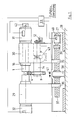
- FIG. 1 The basic concept of the construction of a machine according to FIG. 1 is similar to the construction of a known lathe.
- a machine bed 27 is attached to a foundation 28.
- Two headstocks 29 and 30 are slidably arranged on the machine bed.
- Both headstocks 29 and 30 carry workpiece spindles 16 which are rotatably mounted in the headstocks and can be driven via the motors 31 and 32.
- the workpiece spindles 16 have conventional devices for receiving a workpiece 1 on the heads, which are not described in more detail.
- the motors 31 and 32 which are controlled synchronously via a machine control 33, serve this purpose.
- the headstocks 29 and 30 have on their underside in the machine bed 27 projecting driver pieces 35 and 36, each with a continuous threaded bore, the thread pitch of the one driver piece being opposite to the thread pitch of the other driver piece.
- a corresponding threaded spindle 37 with the thread belonging to the respective driving piece 35 and 36 passes through both driving pieces 36 and 35, the threaded spindle 37 being rotatably and axially immovably mounted in the bearing block 38 which is fastened to the foundation 28.
- the threaded spindle 37 can be connected via a coupling 39 to an electric motor 40, which in turn is connected to the machine control 33 and controlled from there. By actuating the motor 40, the headstocks 29 and 30 can be moved in the direction of arrow 41 and in the opposite direction.
- a workpiece 1 can be removed or also used and clamped by this displacement.
- Such constructions are known and therefore do not have to be described separately here. So that this can all be done in a desired rotational position if necessary, z. B.
- the motor 31 has a rotary encoder 42 arranged on its axis, which gives its information to the machine control 33. This is particularly the case when the workpiece 1 z. B. is a crankshaft.
- a tool carrier 14 designed as a spindle is rotatable in the headstock 30 below the workpiece spindle 16 and is mounted with its axis parallel to the axis of the workpiece spindle 16.
- This tool carrier 14 can be driven in rotation by means of a worm gear and a motor 43 (not specified).
- the motor 43 is again connected to the machine control 33.
- the tool holder 14 is connected to a rotation angle transmitter 12, which in turn transmits its impulses to the machine control 33, so that this rotation angle position of the tool holder 14 is always known.
- the rotational speed of the tool carrier 14 is thereby also known.
- the tool carrier 14 has, between the headstocks 29 and 30, a tool 4 with cutting edges for broaching the workpiece 1.
- the workpiece and the tool are in a relative position to one another, as shown in FIG. 2.
- the tool carrier 14 is rotatably but axially immovably mounted in the headstock 30, the tool 4 always maintains its relative position to the headstock 30. This can be advantageous in mass production if the workpieces 1 can always be clamped in exactly the same positions.
- the tool carrier 4 for example in the interior of the headstock 30, as a splined shaft on which the worm wheel for the connection to the motor 43 is slid axially. The tool carrier 14 can then be displaced axially as desired via a screw drive or a hydraulic drive.
- the tool carrier 14 does not necessarily have to lie in a vertical plane through the axis of the workpiece spindle 16, but may have an arrangement to the side thereof. If one considers the plane 44 according to FIG. 2 as such a vertical plane, then an arrangement as shown in FIG. 4 would be possible with the same relation.
- the motor 31 and possibly the motor 32 are put into operation via the machine control 33 at the necessary speed for a sufficient cutting speed of the workpiece 1, so that the workpiece 1 rotates correspondingly quickly.
- the tool 4 is positioned so that the zone 9 of the workpiece 4 free of cutting edges faces the workpiece 1.
- the tool 4 has individual suitable cutting edges, of which the cutting edge with reference number 7 is the last one.
- the tool 4 penetrates with its cutting edges radially ever deeper into the region of the workpiece 1 to be machined during the rotational movement.
- the last cutting edge 7 is used on the workpiece and completes the intended activity there.
- the zone 9 free of cutting edges turns towards the workpiece 1 and the workpiece 1 can now be changed during the continuous further rotation of the tool 4 in the direction of the arrow 46, which is indeed slow. Such a change occurs with modern feeders within a few seconds.
- the threaded spindle 37 is moved via the motor 40, which has received a corresponding control pulse from the machine control 33, such that the headstocks 29 and 30 move apart in the direction of the arrow 31.
- the machine control 33 receives the information when, ie in which angular position of the tool 4 this can take place, from the rotary angle transmitter 12.
- the motors 31 and 32 are first stopped and the feed device is informed via the machine control 33.
- the feed device not shown, now grips the workpiece 1 and at the same time holds another workpiece 1 ready for the change. Now the headstocks 29 and 30 move apart and the finished workpiece 1 is removed and a workpiece 1 that has not yet been machined is inserted at the same time.
- the feed device informs the machine control 33 of the process that has taken place, which then emits a pulse to the motor 40, so that the headstocks 29 and 30 move together again in the opposite direction to the direction of the arrow 41 and thereby clamp the newly inserted workpiece 1.
- the tool carrier 14 can continue to run continuously with the tool 4.
- the clamping of the workpiece that has taken place can be determined, for example, by the machine controller 33 via the current consumption of the motor 14, which then puts motors 31 and 32 into operation again and possibly also drives the motor 43 again.
- the machine control 33 receives corresponding information about the rotary angle encoder 42.
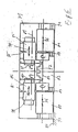
- Figure 3 shows a device in principle as Figure 1, but with two workpiece spindles and two tool carriers. For the sake of clarity, only the right half of the machine is shown. This right side is repeated in mirror image on the other side of the plane marked with arrow A.
- a machine according to FIG. 3 essentially consists of a headstock 47 to which an opposite headstock, not shown, corresponds.
- a shaft 48 is rotatably mounted in the headstock 47.
- the rotational speed and rotational position of the shaft 48 are reported to the machine control 34 via a resolver 49.
- the shaft 48 protrudes with a flying end into the working area between the opposing headstocks 47 of the machine.
- a spindle drum 43 rotatable with the shaft 48 or on the other side 43 ⁇ is provided in a rotationally fixed and axially non-displaceable manner.
- This spindle drum 43 consists essentially of two disks arranged parallel to one another at a distance on the shaft 48, of which the disk closest to the end of the shaft 48 has a toothing for a worm wheel on the outside, into which one of a motor 50 driven worm gear, not specified engages.
- the spindle drum 23 each has a bearing point for the storage of a workpiece spindle 17 or 18.
- the workpiece spindles 17 and 18 have usual clamping means for receiving a workpiece 2 or 3 at the front end, but are axially displaceably mounted in the spindle drum 23.
- An axial displacement of the workpiece spindles 17 and 18 can be effected via fluid cylinders 51, which are provided at the rear end of the workpiece spindles 17 and 18 and are supported on the spindle drum 23 with their cylinder housing.
- An axially acting and unspecified spring arranged in the cylinder housing of the fluid cylinders 51 ensures the clamping movement and the clamping force of the workpiece spindles 17 and 18, respectively.
- To release the fluid cylinders 51 on the piston side facing away from the spring side the pistons in the cylinders are still closed descriptively acted upon by a fluid.
- each workpiece spindle 17 and 18 has a tooth 52 and 53 connected to it in a rotationally fixed and axially immovable manner.
- each gear 52 or 53 can mesh with a gear 54 which is driven by a motor 55.
- Motor 55 is connected to machine control 34 and is controlled from there.
- a carrier drum 20 consisting of two disks arranged at a distance and parallel to one another, in which broaching tools 5 and 6 are arranged on tool carriers 15 and 19.
- the tool carriers 15 and 19 are designed as shafts which are rotatably mounted in the said disks of the carrier drum 20.
- the carrier drum 20 itself is rotatably supported about the axis of rotation 21 in corresponding stands 56 and 56 ⁇ .
- the axis of rotation 21 is connected in a rotationally fixed manner to a worm wheel 57 which can be driven by a motor 58 which in turn is connected to the machine control 34.
- a worm wheel 57 opposite the worm wheel 57, is introduced coaxially to the axis of rotation 21, a drive shaft (not specified in any more detail) which is rotatably connected to a worm wheel 59.
- this drive shaft is rotatably connected to a gear 60 that meshes with pinions 61.
- the cracks 61 are arranged coaxially to the shaft-shaped tool carriers 15 and 19 and can be connected to these shafts in a rotationally fixed manner by means of a coupling (not specified in more detail).
- resolvers which are connected to a device 13 via a control line 62 or 63.
- the worm wheel 57 also has a resolver (not specified in any more detail) which is connected to the device 13 via the control line 64.
- the device 13 itself is connected to the machine control 34 via the control line 65.
- a motor 66 is also connected on the one hand to the machine control 34 and on the other hand mechanically to the worm wheel 59, so that the tools 5 and 6 can also be set in rotation by actuating the motor 66.
- These tools 5 and 6 have zones 10 and 11 free of cutting edges, as shown in FIG.
- the shaft 48 has a distributor ring 67 surrounding it, which is surrounded by a fixed distributor connection.
- Hydraulic lines 69 and 70 are guided in the shaft 48 and are guided via the spindle drum 23 and through the workpiece spindles 17 and 18, respectively, to the front of the piston in the fluid cylinders 51.
- the hydraulic lines 69 and 70 are passed on to the valve 71 via circumferential connection channels in the distributor connection 68.
- This valve has three switching positions and four connections. In the middle position shown, both hydraulic lines 69 and 70 are placed on the tank 72. The two other switching positions enable one or the other fluid cylinder 51 to be acted upon selectively.
- the valve 71 itself is connected to the machine control 34 by its actuating magnets.
- a hydraulic pump 73 which is driven by a motor 74, which in turn is connected to the machine control 34, provides the necessary pressure medium.
- the machine controller 34 is also connected in a suitable manner to a feed device, not shown, so that the activity of the feed device can be coordinated with the machine cycle.
- Figure 3 shows a machine according to the invention in side view with two clamped workpieces, of which the workpiece 2 is just finished, while the workpiece 3 is still completely unworked.
- the workpiece 2 must now be removed from the working area of the tool 5 and the workpiece 3 must be transported there.
- the device 13 receives information via the control line 64 that the tool 5 has been working on the workpiece 2. If the rotary encoder assigned to the tool 5 with the control line 62 is connected to the device 13, the device 13 also receives the information via the control line 62 that the tool 5 has assumed a workpiece change position, as shown in FIG.
- the information supplied to the device 13 via the control line 62 and 64 is supplied to the machine control 34 via the line 65.
- the machine control 34 causes the motor 55 to be put out of operation and causes the feed device with an empty gripper and a gripper filled with a new workpiece to be ready in the change position.
- the motor 66 can be stopped via the machine control 34, but can also run through. It is also possible to simply release the clutch assigned to the score 61.
- the machine control unit 34 starts the motor 50 and thus rotates the spindle drum 23 by 180 °.
- the machine control receives the corresponding angle information from the resolver 49.
- the workpiece 3 is now in the position of the workpiece 2 shown in the drawing, so that the gear 53 meshes with the gear 54 of the motor 55.
- the motor 50 is stopped by the machine control 34 so that the workpiece 3 remains in the working position and the motor 55 rotates the workpiece 3.
- the tool 5 can start machining the workpiece.
- a gripper of the feed device, not shown, is placed on the workpiece 2, which is now in the upper position, and the valve control 71 then switches the valve 71 into the switch position with the crossed arrows.
- the workpiece spindle 17 is moved backwards along the machine axis 22 and the workpiece 2 can now be removed from the feed device.
- the feed device brings a new workpiece into the clamping position and reports this to the machine control 34, which then the valve 71 moves back into the middle position, whereby the line 69 is placed on the tank and the workpiece spindle 17 is pushed forward again by the axially acting spring in the fluid cylinder 51 and the newly inserted workpiece is thus clamped.
- the spindle drum 23 By rotating the spindle drum 23 again by 180 °, this newly inserted workpiece can now be brought back into the working position in order to be processed by the tool 5.
- the machine according to FIG. 3 can be equipped with fixed tools 5, as described for FIG. 1.
- a tool changing device as shown in FIG. 3.
- two stands 56 and 56 ⁇ attached to the foundation, which serve as a bearing stand for an axis of rotation 21.
- the discs of the carrier drum 20 have, in a diametrically opposite arrangement, bearing points in which tool carriers 15 and 19 designed as shafts are rotatably mounted.
- the shafts 15 and 19 carry a tool 5 and 6 respectively.
- the shafts 15 and 19 are each connected to a pinion 61 that can be connected in a rotationally fixed manner to the shafts by means of an unspecified coupling or can be released so that it does not entrain the shafts can rotate on it.
- These pinions 61 are in engagement with a central gearwheel 60 with the axis of rotation 21.
- the central gearwheel 60 Via the axis of rotation 21, the central gearwheel 60 is connected in a rotationally fixed manner to a worm gear 59, the worm gear 59 being able to be driven by a motor 66 via a corresponding worm.
- the motor 66 is controlled by the machine control 34.
- the worm wheel 59 and the central gear wheel 60 associated therewith and non-rotatably connected to it are independent of the rotational movement of the carrier drum 20 assigned axis or shaft rotatable.
- the shaft carrying the carrier drum 20 has a worm wheel 57 which can be driven by the motor 58 via a corresponding worm drive.
- the entire carrier drum 20 can be rotated by driving the worm wheel 57.
- a rotational angle sensor 12 ' is provided, which is connected via the line 64 to a corresponding evaluation device 13.
- the tool carriers 15 and 19, which are designed as shafts, also have suitable rotary angle sensors which are connected to the device 13 via the lines 62 and 63, as has already been described.
- the tool 5 or the tool 6 or, if required, the tools 5 and 6 alternately can be brought into the working position.
- any state of the machine that characterizes the change requirement can be queried and a corresponding signal can be sent to the machine control.
- the command for the tool change can also be entered manually in the machine control 34.
- the machine control then causes the motor 58 to rotate the carrier drum 20 via the worm wheel 57.
- the motor 58 is stopped again after a 180 ° rotation, which is reported from the assigned rotary angle transmitter via the control line 64 to the device 13 and directly to the machine control 34.
- the rotational angle position of the tool carrier 19 is queried and reported to the device 13, for example, via the control line 63.
- the combination of the signal from the control line 65 and the control line 63 is determined by the device 13 via the control line 65 fed to the machine control 34, which thereby knows which tool is in the working position and which rotational position of this tool. If the rotational position deviates from the target position, the machine control 34 sets the motor 66 into operation accordingly and the clutch assigned to the pinions 61 is switched so that the corresponding tool can be rotated into the correct rotational position. This is reported again via the correspondingly assigned rotary encoder and the device 13 to the machine control 34, which is thus informed of the correct rotational position of the tool.
- a rotary movement of the carrier drum 20 and thus of the associated tools can take place simultaneously, but also independently of a rotary movement of the spindle drum 23.
- the tools used in a machine according to FIG. 3 can be both tools with only one zone 9 free of cutting edges, as shown in FIG. 2, and such tools with several zones 10 and 11 free of cutting edges, as shown in FIG.
- the base body carrying the cutting elements can be formed in one piece and connected to the tool carrier 15, for example, via a known tongue and groove connection.
- the cutting edge carriers 24 and 25 each cover a peripheral region of significantly less than 180 °, so that when these cutting edge carriers are arranged opposite one another, a peripheral region 26 of sufficient Size remains free twice, whereby the necessary zones 10 and 11 free of cutting edges are then formed.
- the flange of the base body 75 is preferably interrupted up to the hub.
- the cutting edge carriers 24 and 25 designed as segments themselves can have a circular outer contour with the radius R. It is also possible to dimension the two radii R differently. The centers of these radii R can each be offset by the amount 76 or 77 from the center 78 of the tool carrier 15. These amounts 76 and 77 can of course also be different. This enables tools to be created for a wide variety of work tasks. In addition, it is of course also possible to assemble the cutting edge carriers 24 and 25 from substantially smaller segments, as seen in the circumferential direction, and thus to construct the entire cutting region from individual small segments.
- the embodiment according to FIG. 6 is similar to an embodiment according to FIG. 1.
- the embodiment according to FIG. 6 can be regarded as shown in a top view in FIG.
- a machine bed 79 is arranged parallel to a foundation surface or floor surface, which is not described in any more detail.
- two headstocks 80 and 81 are arranged on sliding guides 90 and 91 so as to be displaceable and positionable in an opposing arrangement and with the same axis of rotation or center line 82.
- a workpiece 92 for example a crankshaft, can be picked up and driven in rotation by the workpiece spindles 83 and 84 of these headstocks 80 and 81.
- headstocks 80 and 81 two further headstocks 85 and 86 are arranged, so that each headstock 81 and 80 is assigned a headstock 85 and 86, respectively.
- the headstocks 85 and 86 drive tool carriers 87 and 88 around a common center line 89.
- the tool carrier 87 and 88 can tools z. B. wear according to Figure 4 or Figure 2.
- the workpiece 92 is preferably a crankshaft, as is also indicated in FIG. 2.
- the machine bed 79 can be designed in a U-shape and thereby leave a portal opening 93 centrally.
- This portal opening 93 can leave access to a chip pit.
- the crankshaft can be received by the headstocks 80 and 81 and driven in rotation.
- the crankshaft can then be machined at the desired locations from the tools on the tool carriers 87 and 88, which are not described in any more detail.
- Another possibility of travel can be provided in the direction of arrows 95.
- the headstock 85 or 86 it is only necessary to arrange the headstock 85 or 86 so that it can be displaced and positioned on a carriage (not specified) in the direction of arrows 94.
- This carriage not designated in any more detail, can then be displaced and positioned on guides of the machine bed 79 in the direction of the arrows 95. In this way, the entire machine can be easily adapted to different working conditions.
- a particular advantage is obtained when the machine bed 79 is placed upright in the arrangement according to FIG. 6, so that it forms a portal.
- the foundation is then indicated by line 97.
- the portal opening 97 then allows the workpiece 92 to be freely cycled, perpendicular to the plane of the drawing.
- a chip pit can be provided in the foundation 97, which is also not hindered by the bed 79.
- the machine designs described are relatively easy to set up when considering their respective machining options when using tools with zones free of cutting edges and can nevertheless solve a variety of machining tasks. Non-productive times caused by tool movements that are not used for workpiece machining are minimized. With such machines, the application rate of the machines can be improved and the machine structure itself can be simplified at the same time using the corresponding working method.
Landscapes
- Engineering & Computer Science (AREA)
- Mechanical Engineering (AREA)
- Turning (AREA)
- Milling, Broaching, Filing, Reaming, And Others (AREA)
- Machine Tool Sensing Apparatuses (AREA)
Abstract
Description
Die Erfindung betrifft ein Verfahren zum Drehräumen von rotationssymmetrischen Werkstücken mit einem Werkzeug mit in einer Radialebene zum Werkstück und auf gekrümmter Bahn angeordneten und bewegten, mit dem Werkstück in Eingriff bringbaren Schneiden, sowie eine Vorrichtung zur Durchführung des Verfahrens.The invention relates to a method for the rotary broaching of rotationally symmetrical workpieces with a tool with blades arranged and moved in a radial plane to the workpiece and on a curved path, which can be brought into engagement with the workpiece, and a device for carrying out the method.
Ganz allgemein sind Verfahren und Einrichtungen der oben beschriebenen Art bereits bekannt geworden durch die DE-OS 33 40 830. Solche Einrichtungen weisen jedoch den Nachteil auf, daß nach Durchführung der Räumarbeit zunächst das Werkstück entnommen und danach der Räumtisch seinen gesamten langen Hubweg zurückfahren muß, bevor da s nächste Werkstück eingelegt werden kann. Hierdurch entstehen unerwünschterweise hohe Nebenzeiten.In general, methods and devices of the type described above have already become known from DE-OS 33 40 830. However, such devices have the disadvantage that after the broaching work has been carried out, the workpiece must first be removed and then the broaching table must travel its entire long travel distance. before the next workpiece can be inserted. This creates undesirably high idle times.
Es ist jedoch auch bereits vorgeschlagen worden, die Räumwerkzeuge nicht mehr als gerade Räumwerkzeuge, die während der Zerspanung verschoben werden müssen, auszubilden, sondern die Schneidelemente der Räumwerkzeuge auf einer spiraligen Kontur über einen Umfangsbereich von 360° gleichmäßig zu verteilen. Eine entsprechende Skizze ist dargestellt in dem Pospekt der Firma Heinlein "Neues Fertigungsverfahren für die Massenproduktion". Die Skizze ist überschrieben mit dem Begriff "Rotations-Drehräumen". Das Räumwerkzeug wird nicht mehr auf einem Schlitten zur Erzeugung der Vorschubbewegung verschoben, sondern um eine Achse gedreht. Die spiralig ansteigende Kontur der Linie auf der die Scheidelemente angeordnet sind, sorgt hierbei für die Tiefenzustellung. In welcher Weise das Werkzeug aufgenommen ist, und außer der genannten Drehbewegung beweglich ist, ist diesen Unterlagen nicht zu entnehmen.However, it has also already been proposed that the broaching tools should no longer be designed as straight broaching tools that have to be displaced during machining, but rather that the cutting elements of the broaching tools should be distributed uniformly over a circumferential area of 360 ° over a spiral contour. A corresponding sketch is shown in the prospect of the Heinlein company "New manufacturing process for mass production". The sketch is titled "Rotation-Turning Rooms". The broaching tool is no longer moved on a slide to generate the feed movement, but rotated around an axis. The spiraling contour of the line on which the cutting elements are arranged ensures the infeed. The way in which the tool is received and is movable in addition to the mentioned rotary movement, cannot be found in these documents.
Aus der Zeitschrift "Maschinenmarkt" (1986) Nr. 34, Seite 28, mittlere Spalte, Bild 8, ist eine Anordnung von drei Räumwerkzeugen auf jeweils einem Werkzeugträger bekannt geworden, wobei die Werkzeugträger koaxial zur Werkstückachse angeordnet sind und die Schneidelemente sich auf dem Werkzeugträger auf gekrümmter Bahn befinden und vom Werkzeugträger gedreht, also auf gekrümmter Bahn bewegt werden. Die Schneidelemente sind hierbei am Werkzeug über einen Umfangsbereich von weniger als 180° angeordnet. Die Anordnung des Werkzeuges soll der Entlastung des Werkstückes von unerwünschten Querkräften, die aus der Bearbeitung resultieren, dienen. Weitergehende Informationen sind dieser Veröffentlichung nicht zu entnehmen. Auch bei dieser Anordnung entstehen hohe Nebenzeiten, weil nur im werkzeugfreien Bereich das Werkstück gewechselt werden kann und daher der werkzeugfreie Bereich genügend lange für den Werkstückwechsel beibehalten werden muß. Nach dem Werkstückwechsel muß dann über den gesamten Freibereich wieder eine Drehung der Werkzeuge bis zum Werkzeugeingriff erfolgen. Eine Einsparung von Nebenzeiten ist bei einer solchen Anordnung nicht möglich.From the magazine "Maschinenmarkt" (1986) No. 34,
Dem gegenüber liegt der Erfindung die Aufgabe zugrunde, ein Verfahren der eingangs beschriebenen Art vorzuschlagen, bei dessen Anwendung die Nebenzeiten verringert werden können. Weiterhin soll ein einfacherer Maschinenaufbau möglich werden. Auch soll eine Maschine zur Durchführung des erfindungsgemäßen Verfahrens vorgeschlagen werden.In contrast, the object of the invention is to propose a method of the type described in the introduction, in the use of which the idle times can be reduced. Furthermore, a simpler machine structure should be possible. A machine for implementing the method according to the invention is also to be proposed.
Die Aufgabe hinsichtlich des Verfahrens ist erfindungsgemäß dadurch gelöst, daß die Be- und Entladung mit Werkstücken erfolgt, ohne Unterbrechung der Bewegung des Werkzeuges, jedoch nach der Bearbeitung durch die letzte Schneidkante im Bereich einer nachfolgenden, von Schneidkanten freien Zone des Werkzeuges. Dies bedeutet, daß die Drehbewegung des Räumwerkzeuges dann, wenn die letzte Schneidkante des Räumwerkzeuges die Fertigbearbeitung des Werkstückes beendet hat, unverändert beibehalten werden soll, daß sich jedoch dieser letzten Schneidkante ein schneidkantenfreier Bereich am Werkzeug anschließt, so daß in diesem schneidkantenfreien Bereich ohne Radialbewegung des Werkzeuges das Werkstück gewechselt werden kann. Mit modernen Zuführeinrichtungen kann ein solcher Werkstückwechsel von kleineren Wellen oder z.B. Kurbelwellen von Kfz-Motoren in wenigen Sekunden durchgeführt werden. Die Lücke im Werkzeug kann so bemessen sein, daß unmittelbar nach Beendigung des Werkstückwechselvorgangs die erste Schneide wieder am Beginn des Arbeitsprozesses steht und damit am Werkstück die Bearbeitung beginnt. Auf diese Art und Weise sind Rückhubzeiten oder Leerzeiten, um das Werkzeug in Arbeitsposition zu bringen, minimierbar bzw. vollständig vermeidbar. Gleichzeitig kann bei der Maschinenkonstruktion ein gesonderter Schlitten mit Antrieb und Steuerung für eine Radialbewegung des Werkzeuges entfallen.The object with regard to the method is achieved according to the invention in that the loading and unloading takes place with workpieces, without interrupting the movement of the tool, but after machining by the last cutting edge in the area of a subsequent one, from Cutting edge free zone of the tool. This means that when the last cutting edge of the broaching tool has finished machining the workpiece, the rotary movement of the broaching tool should be maintained unchanged, but this last cutting edge is followed by a cutting edge-free area on the tool, so that in this cutting edge-free area without radial movement of the The workpiece can be changed. With modern feeding devices, such a workpiece change from smaller shafts or, for example, crankshafts from motor vehicle engines can be carried out in a few seconds. The gap in the tool can be dimensioned such that the first cutting edge is again at the beginning of the work process immediately after the workpiece change process has ended and machining therefore begins on the workpiece. In this way, return stroke times or idle times to bring the tool into the working position can be minimized or completely avoided. At the same time, a separate slide with drive and control for a radial movement of the tool can be omitted in the machine design.
Eine Alternative des erfindungsgemäßen Verfahrens sieht vor, daß nach der Bearbeitung d es Werkstückes durch die letzte Schneidkante das Werkzeug in gleicher Bewegungsrichtung in eine Werkstückwechselposition bewegt und für den Zeitraum des Werkstückwechsels stillgesetzt wird. Auch hierdurch werden die bereits beschriebenen Vorteile erreicht, wenngleich an der notwendigen Maschine Steuerungsmittel für die Stillsetzung des Werkzeuges in der Werkzeugwechselposition vorgesehen sein müssen. Es sei in diesem Zusammenhang betont, daß die Bewegung des Werkzeuges nicht unbedingt ausschließlich eine Drehbewegung um einen feststehenden Mittelpunkt sein muß. Dies ist nur eine Möglichkeit Schneiden auf gekrümmter Bahn zu bewegen. Weiterhin soll darauf hingewiesen werden, daß der Begriff Be- und Entladung ganz allgemein das Einbringen eines Werkstücks in den Arbeitsbereich eines zugeordneten Werkzeuges oder das Entfernen aus diesem Arbeitsbereich bedeutet.An alternative of the method according to the invention provides that after the processing of the workpiece by the last cutting edge, the tool is moved in the same direction of movement into a workpiece change position and is stopped for the period of the workpiece change. This also achieves the advantages already described, although control means for stopping the tool in the tool changing position must be provided on the necessary machine. It should be emphasized in this connection that the movement of the tool does not necessarily have to be exclusively a rotary movement around a fixed center point. This is only one way to move cutting on a curved path. It should also be pointed out that the term loading and unloading generally refers to the introduction of a workpiece into the work area of a assigned tool or removing from this work area.
Ergänzend wird nach der Erfindung vorgeschlagen, daß als Werkstückwechselposition am Werkzeug mindestens eine einer letzten Schneidkante nachfolgende, von Schneidkanten freie Zone vorgesehen ist, die in zum Werkstück gegenüberliegender Position bewegt und stillgesetzt wird. Dies ist die einfachste Möglichkeit der Schaffung und des Einfahrens in eine Werkstückwechselposition.In addition, it is proposed according to the invention that at least one zone following a last cutting edge and free of cutting edges is provided as the workpiece change position on the tool and is moved and stopped in the position opposite the workpiece. This is the easiest way to create and retract a workpiece change position.
Zur Durchführung des erfindungsgemäßen Verfahrens wird eine Maschine vorgeschlagen mit einer um die Maschinenachse drehantreibbaren Werkstückspindel und einem beweglichen Werkzeugträger mit daran angeordneten Schneidkanten, wobei der Werkzeugträger eine Bewegung der Schneidkanten auf gekrümmter Bahn ermöglicht, bei der Mittel vorgesehen sind, die eine Winkellage des Werkzeugträgers für den Arbeitsbeginn und eine Winkellage des Werkzeugträgers für die Entnahme erfassen, wobei in der Winkellage für die Entnahme eine von Schneidkanten freie Zone dem Werkstück zugewandt ist, und Steuersignale für die Be- und Entladung und mindestens den Arbeitsbeginn an die Maschinensteuertung weiterleiten. Hierdurch gelingt es mit einfachen Mitteln die richtige Lage der Werkzeuge für die Einleitung und Durchführung des Werkstückwechsels zu erfassen und die Maschine entsprechend zu steuern.To carry out the method according to the invention, a machine is proposed with a workpiece spindle which can be driven in rotation about the machine axis and a movable tool carrier with cutting edges arranged thereon, the tool carrier allowing movement of the cutting edges on a curved path, in which means are provided which provide an angular position of the tool carrier for the Detect the start of work and an angular position of the tool holder for removal, in the angular position for removal a zone free of cutting edges facing the workpiece, and forward control signals for loading and unloading and at least the start of work to the machine control. This enables the correct position of the tools for initiating and carrying out the workpiece change to be detected with simple means and the machine to be controlled accordingly.
Weiter ist nach der Erfindung vorgeschlagen, daß die Werkstückspindel in eine vorgegebene, feste Winkellage einfahrbar ist. Dies ist insbesondere dann günstig, wenn das Werkstück unsymmetrische Formen aufweist, wie z. B. bei einer Kurbelwelle. Es existiert dann eine bevorzugte Werkstücklage für den Werkstückwechsel, der dann, wenn die Werkstückspindel in eine vorgegebene feste Winkellage einfahrbar ist und eingefahren ist, durchgeführt werden kann.It is also proposed according to the invention that the workpiece spindle can be moved into a predetermined, fixed angular position. This is particularly advantageous when the workpiece has asymmetrical shapes, such as. B. in a crankshaft. There is then a preferred workpiece position for the workpiece change, which can be carried out when the workpiece spindle can be retracted and retracted into a predetermined fixed angular position.
Eine Ausgestaltung der Erfindung sieht vor, daß mindestens ein weiterer Werkzeugträger vorgesehen ist. Hierdurch gelingt es mindestens zwei Werkzeuge zum Einsatz zu bringen, und zwar je nach Maschinenkonstruktion entweder abwechselnd oder gleichzeitig, wobei die verwendeten Werkzeuge auch gleich oder unterschiedlich sein können und am Werkzeugträger auf unterschiedlichen Positionen angeordnet sein können.An embodiment of the invention provides that at least one further tool carrier is provided. This makes it possible to use at least two tools, either alternately or simultaneously, depending on the machine design, the tools used also being able to be the same or different and being able to be arranged on the tool carrier in different positions.
Ergänzend ist dann nach der Erfindung vorgeschlagen, daß die Werkzeugträger in mindestens einer drehbeweglichen Trägertrommel angeordnet sind. Hierdurch können die Werkzeuge auf einfache Art und Weise in Arbeitsposition gebracht oder aus der Arbeitsposition entfernt werden. Es ist aber auch möglich mit der drehbeweglichen Trägertrommel zusätzlich oder ausschließlich den Werkzeugvorschub zu bewirken.In addition, it is then proposed according to the invention that the tool carriers are arranged in at least one rotatable carrier drum. As a result, the tools can be brought into the working position or removed from the working position in a simple manner. However, it is also possible to additionally or exclusively effect the tool feed with the rotatable carrier drum.
Weiterhin ist nach der Erfindung vorgeschlagen, daß die Drehachse der Trägertommel außerhalb der Maschinenachse angeordnet ist. Hierdurch ist Platz geschaffen für einen unproblematischen Werkstückwechsel, der nicht zu unnötigen Nebenzeiten zwingt.Furthermore, it is proposed according to the invention that the axis of rotation of the carrier drum is arranged outside the machine axis. This creates space for an unproblematic workpiece change that does not force unnecessary idle times.
Ergänzend ist nach der Erfindung noch vorgeschlagen, daß die Drehachse der Trägertrommel parallel zur Maschinenachse angeordnet ist. Dies ist eine vorteilhafte und unproblematische Anordnung.In addition, it is proposed according to the invention that the axis of rotation of the carrier drum is arranged parallel to the machine axis. This is an advantageous and unproblematic arrangement.
Es ist weiter vorgesehen, daß die Werkzeugträger als Spindeln ausgebildet sind, in parallel zueinander verlaufender Anor dnung. Spindeln sind einfach zu lagern und der Drehantrieb ist einfach zu lagern. Die Übertragung der Drehbewegung auf zugeordnete Werkzeuge ist ebenfalls einfach, so daß sich durch diese Konstruktion auf einfachste Art und Weise die notwendige Werkzeugbewegung erzeugen läßt.It is further contemplated that the tool carriers are designed as spindles, in parallel Anor extension. Spindles are easy to store and the rotary drive is easy to store. The transfer of the rotary movement to associated tools is also simple, so that the necessary tool movement can be generated in the simplest way by this construction.
Es ist weiter nach der Erfindung noch ergänzend vorgesehen, daß die Spindeln von mindestens einer drehbeweglichen Trägertrommel getragen werden. Die vorteilhafte Konstruktion der Trägertrommel wurde bereits erwähnt. Selbstverständlich sind auch Spindeln als Werkzeugträger besonders einfach in Trägertrommeln zu lagern. Der Aufbau wird insgesamt vereinfacht.It is further provided according to the invention that the spindles are carried by at least one rotatable carrier drum. The advantageous construction of the carrier drum has already been mentioned. Of course, spindles as tool carriers are also particularly easy to store in carrier drums. The overall structure is simplified.
Weiter ergänzend ist nach der Erfindung noch vorgeschlagen, daß jede Trägertrommel in mindestens zwei vorgegebene Winkelpositionen einfahrbar ist. Hierdurch können die Werkzeuge einfach und automatisch bewegt und in eine gewünschte Lage gebracht werden.In addition, it is also proposed according to the invention that each carrier drum can be retracted into at least two predetermined angular positions. As a result, the tools can be moved easily and automatically and brought into a desired position.
In weiterer Ausgestaltung der erfindungsgemäßen Einrichtung ist vorgeschlagen, daß mindestens zwei Werkstückspindeln vorgesehen sind. Hierdurch wird die Maschine flexibler und erreicht eine höhere Produktivität. Es ist hierdurch möglich, Maschinen zu gestalten, die sehr große Stückzahlen in der Serie wirtschaftlich fertigen. Es ist aber auch möglich, mit diesem Konstruktionsmerkmal und in Kombination mit vorangegangenen Merkmalen eine sehr flexible Maschine zu gestalten, die unterschiedliche Werkstücke in unterschiedlichen Arbeitspositionen mit unterschiedlichen Werkzeugen bearbeiten kann.In a further embodiment of the device according to the invention it is proposed that at least two workpiece spindles are provided. This makes the machine more flexible and achieves higher productivity. This makes it possible to design machines that economically manufacture very large quantities in series. However, it is also possible to use this design feature and in combination with previous features to design a very flexible machine that can process different workpieces in different working positions with different tools.
Weiterhin ist nach der Erfindung noch vorgesehen, daß in Umfangsrichtung am Werkzeugträger Schneidkantenträger mit Schneidkanten angeordnet sind, wobei mindestens ein Umfangsbereich zur Bildung einer Entnahmelücke frei ist von Schneidkantenträgern. Auf diese Art und Weise wird ein Werkzeug aus einzelnen Teilstücken augefbaut, wobei am Umfang solche Teilstücke einfach weggelassen werden können, um eine Entnahmelücke zu bilden. Eine besondere Formgestaltung des Werkzeuges zur Bildung einer solchen Entnahmelücke ist dann nicht mehr notwendig. Der Einsatz eines Werkzeugträgers, auf dem Schneidkanten träger angeordnet werden können, erreicht daher den angestrebten Zweck, das erfindungsgemäße Verfahren zu ermöglichen und stellt gleichzeitig ein vereinfachendes Merkmal der erfindungsgemäßen Maschine dar.Furthermore, according to the invention it is also provided that cutting edge carriers with cutting edges are arranged in the circumferential direction on the tool carrier, at least one peripheral region being free of cutting edge carriers to form a removal gap. In this way, a tool is built up from individual sections, it being possible to simply omit such sections on the circumference in order to form a removal gap. A special shape of the tool to form such a removal gap is then no longer necessary. The use of a tool holder on the cutting edges Can be arranged carrier therefore achieves the intended purpose of enabling the method according to the invention and at the same time represents a simplifying feature of the machine according to the invention.
Es ist auch nach der Erfindung vorgesehen, daß auf einem Machinenbett angeordnet, mindestens zwei Spindelstöcke in sich gegenüberliegender Anordnung und mit gemeinsamer Mittellinie der Werkstückspindel vorgesehen sind, sowie mindestens ein weiterer Spindelstock für den drehantreibbaren Werkzeugträger wobei die Mittellinie jedes Werkzeugträgers parallel zur Mittellinie der Werkstückspindeln verläuft. Dies ist ein einfacher und übersichtlicher Maschinenaufbau, der gleichzeitig eine gute Handhabung des Werkstückes erlaubt.It is also provided according to the invention that arranged on a machine bed, at least two headstocks in an opposing arrangement and with a common center line of the workpiece spindle are provided, and at least one further headstock for the rotationally drivable tool carrier, the center line of each tool carrier running parallel to the center line of the workpiece spindles . This is a simple and clear machine structure, which also allows good handling of the workpiece.
Ergänzend ist nach der Erfindung noch vorgeschlagen, daß jeder Spindelstock für einen Werkzeugträger parallel zu der Mittellinie der Werkstückspindeln verschiebbar und positionierbar angeordnet ist. Hierdurch können die zugeordneten Werkzeuge auf axial unterschiedliche Lagen des Werkstückes und auf axial unterschiedlich liegende Arbeitsstellen am Werkstück eingestellt werden.In addition, it is also proposed according to the invention that each headstock for a tool carrier is arranged to be displaceable and positionable parallel to the center line of the workpiece spindles. As a result, the assigned tools can be set to axially different positions of the workpiece and to axially differently located work stations on the workpiece.
Ergänzend ist nach der Erfindung vorgeschlagen, daß jeder Spindelstock für einen Werkzeugträger vertikal zur Mittellinie eines Werkzeugträgers verschiebbar und positionierbar angeordnet ist. Hierdurch gelingt es einerseits die gesamte Einrichtung auf unterschiedliche Durchmesserlagen der Werkzeuge und andererseits auf unterschiedliche Fertigdurchmesser am Werkstück bei gleichen Werkzeugabmessungen einzustellen.In addition, it is proposed according to the invention that each headstock for a tool carrier is arranged to be displaceable and positionable vertically to the center line of a tool carrier. In this way it is possible on the one hand to set the entire device to different diameter positions of the tools and on the other hand to different finished diameters on the workpiece with the same tool dimensions.
Eine weitere Variationsmöglichkeit ergibt sich nach der Erfindung dadurch, daß jeder Spindelstock für eine Werkstückspindel verschiebbar und positionierbar angeordnet ist. Hierdurch wird auch eine zusätzliche Einstellung auf unterschiedliche Werkstücklängen möglich.Another possible variation results according to the invention in that each headstock for a workpiece spindle is displaceable and is positioned positionable. This also enables additional adjustment to different workpiece lengths.
Weitere Vorteile werden nach der Erfindung dad urch erzielt, daß das Maschinenbett vertikal angeordnet ist, bei horizontalem Verlauf der Mittellinien der Spindeln. Hierdurch wird einerseits ein günstiger Zugang zum Werkstück und andererseits ein günstiger Späneabtransport erreicht.Further advantages are achieved according to the invention in that the machine bed is arranged vertically, with the center lines of the spindles running horizontally. In this way, on the one hand, favorable access to the workpiece and, on the other hand, more favorable chip removal is achieved.
Eine weitere Ausgestaltung ist nach der Erfindung darin zu sehen, daß das Maschinenbett als Portal gestaltet ist. In waagerechter Anordnug erlaubt der Freiraum des Portals den einfachen Zugang zu einer Spänegrube. In vertikaler Anordnung des Maschinenbettes in der nach der Erfindung vorgeschlagenen Art, ist ohnehin ein günstiger Zugang zu einer Spänegrube möglich und es ist gleichzeitig ein Durchtakten des Werkstückes durch die Maschine, also durch das Portal des Maschinenbettes problemlos möglich.According to the invention, a further embodiment is to be seen in the fact that the machine bed is designed as a portal. In a horizontal arrangement, the free space of the portal allows easy access to a chip pit. In a vertical arrangement of the machine bed in the manner proposed according to the invention, favorable access to a chip pit is possible anyway, and at the same time the workpiece can be clocked through the machine, that is to say without problems, through the portal of the machine bed.
Auch ist nach der Erfindung noch vorgeschlagen, daß jeder Werkzeugspindelstock oberhalb der zugeordneten Werkstückspindelstöcke angeordnet ist. Hierdurch wird wiederum ein günstiger Zugang zum Werkstück erreicht und gleichzeitig verhindert, daß Werkzeug und Werkzeugträger durch Schmutz- und Spänefall belastet werden.It is also proposed according to the invention that each tool headstock is arranged above the associated workpiece headstocks. This in turn provides favorable access to the workpiece and at the same time prevents tools and tool carriers from being burdened by dirt and chips.
Schließlich ist nach der Erfindung noch vorgeschlagen, daß die Drehgeschwindigkeit von Werkstückspindel und/oder Werkzeugträger veränderbar ist. Hierdurch kann das pro Zeiteinheit entstehende Zerspanungsvolumen konstant gehalten oder auch verändert werden. Hierdurch kann eine Anpassung an das Schwingungsverhalten des Werkstückes und/oder an die Schneidleistung der jeweils in Eingriff befindlichen Schneidplatten erfolgen. Die Leistung der Maschine und die Qualität des Arbeitsergebnisses können somit optimiert werden.Finally, it is also proposed according to the invention that the rotational speed of the workpiece spindle and / or tool carrier can be changed. As a result, the machining volume generated per unit of time can be kept constant or also changed. In this way, an adaptation to the vibration behavior of the workpiece and / or to the cutting performance of the cutting inserts in engagement in each case can take place. The performance of the machine and the quality of the work result can thus be optimized.
Die Erfindung soll nun anhand der beigefügten Skizzen näher erläutert werden.The invention will now be explained in more detail with reference to the attached sketches.
Es zeigen:
- Figur 1: drehbankähnliche Maschine mit Räumwerkzeug und Werkstück in Seitenansicht und Teilschnitt
- Figur 2: Relation von Werkstück und Werkzeug bei einer Einrichtung nach Figur 1 im Querschnitt
- Figur 3: im wesentlichen rechte Hälte der erfindungsgemäßen Räummaschine in Seitenansicht
- Figur 4: mögliche Entnahmeposition zwischen Werkstück und Werkzeug im Querschnitt.
- Figur 5: Schnitt entlang der Linie I-I nach Figur 4
- Figur 6: Räummaschine in Vorderansicht
- Figure 1: Lathe-like machine with broaching tool and workpiece in side view and partial section
- Figure 2: Relation of workpiece and tool in a device according to Figure 1 in cross section
- Figure 3: essentially right halves of the broaching machine according to the invention in side view
- Figure 4: possible removal position between workpiece and tool in cross section.
- Figure 5: Section along the line II of Figure 4
- Figure 6: Broaching machine in front view
Der Aufbau einer Maschine nach Figur 1 ähnelt in seiner Grundkonzeption dem Aufbau einer bekannten Drehmaschine. Ein Maschinenbett 27 ist auf einem Fundament 28 befestigt. Auf dem Maschinenbett sind verschieblich zwei Spindelstöcke 29 und 30 angeordnet. Beide Spindelstöcke 29 und 30 tragen Werkstückspindeln 16, die in den Spindelstöcken drehbar gelagert und über die Motoren 31 und 32 antreibbar sind. Die Werkstückspindeln 16 weisen an den nicht näher bezeichneten Köpfen übliche Einrichtungen zur Aufnahme eines Werkstückes 1 auf. Für eine Bearbeitung des Werkstückes 1 muß dieses in Drehbewegung versetzt werden. Hierzu dienen die Motoren 31 und 32, die über eine Maschinensteuerung 33 synchron gesteuert werden. Je nach Bauart des Werkstückes ist es jedoch auch möglich, auf einen der beiden Motoren zu verzichten und das Werkstück nur über eine motorgetriebene Werkstückspindel anzutreiben und die andere Werkstückspindel leer mitlaufen zu lassen.The basic concept of the construction of a machine according to FIG. 1 is similar to the construction of a known lathe. A
Die Spindelstöcke 29 und 30 weisen an ihrer Unterseite in das Maschinenbett 27 hineinragende Mitnehmerstücke 35 und 36 auf, mit je einer durchgehenden Gewindebohrung, wobei die Gewindesteigung des einen Mitnehmerstückes entgegengesetzt zur Gewindesteigung des anderen Mitnehmerstückes ist. Durch beide Mitnehmerstücke 36 und 35 geht eine entsprechende Gewindespindel 37 mit dem zum jeweiligen Mitnehmerstück 35 bzw. 36 gehörenden Gewinde hindurch, wobei die Gewindespindel 37 im Lagerbock 38, der am Fundament 28 befestigt ist, drehbar und axial unverschiebbar gelagert ist. Die Gewindespindel 37 kann über eine Kupplung 39 mit einem Elektromotor 40 verbunden sein, der seinerseits wieder mit der Maschinensteuerung 33 verbunden und von dort gesteuert wird. Durch eine Betätigung des Moto rs 40 können die Spindelstöcke 29 und 30 in Richtung des Pfeils 41 und entgegengesetzt hierzu verschoben werden. Durch diese Verschiebung wird ein Werkstück 1 entnehmbar oder auch einsetzbar und spannbar. Es ist jedoch auch denkbar, nicht die Spindelstöcke 29 und 30 zu verschieben, sondern ausschließlich die Werkstückaufnahmeeinrichtungen an den Werkstückspindeln 16 so zu gestalten, daß ein problemloser Werkstückwechsel möglich wird. Hierzu ist es auch denkbar, nur die Werkstückspindeln 16 selbst oder Teile davon axial zu verschieben. Solche Konstruktionen sind bekannt und müssen daher hier nicht gesondert beschrieben werden. Damit dies alles bei Bedarf auch in einer gewünschten Drehlage geschehen kann, weist z. B. der Motor 31 einen auf seiner Achse angeordneten Drehwinkelgeber 42 auf, der seine Information an die Maschinensteuerung 33 gibt. Dies ist besonders dann der Fall, wenn das Werkstück 1 z. B. eine Kurbelwelle ist.The
Im Spindelstock 30 ist unterhalb der Werkstückspindel 16 ein als Spindel ausgebildeter Werkzeugträger 14 drehbar und mit seiner Achse parallel zur Achse der Werkstückspindel 16 gelagert. Dieser Werkzeugträger 14 kann über ein nicht näher bezeichnetes Schneckengetriebe und einen Motor 43 drehangetrieben werden. Der Motor 43 ist wieder mit der Maschinensteuerung 33 verbunden. Der Werkzeugträger 14 ist verbunden mit einem Drehwinkelgeber 12, der seine Impulse wiederum an die Maschinensteuerung 33 abgibt, so daß diese Drehwinkellage des Werkzeugträgers 14 stets bekannt ist. Zusätzlich ist hierdurch auch die Drehgeschwindigkeit des Werkzeugträgers 14 bekannt.A
In fliegender Anordnung weist der Werkzeugträger 14 zwischen den Spindelstöcken 29 und 30 ein mit Schneidkanten besetztes Werkzeug 4 zum Räumen des Werkstücks 1 auf. Während der Bearbeitung haben das Werkstück und das Werkzeug eine relative Lage zueinander, wie dies in Figur 2 dargestellt ist.In a flying arrangement, the
Ist, wie im Ausführungsbeispiel nach Figur 1, der Werkzeugträger 14 drehbar, aber axial unverschiebbar im Spindelstock 30 gelagert, dann behält das Werkzeug 4 seine relative Lage zum Spindelstock 30 immer bei. Dies kann bei der Massenfertigung dann vorteilhaft sein, wenn es gelingt, die Werkstücke 1 in immer exakt gleichen Positionen zu spannen. Es ist aber auch problemlos möglich, den Werkzeugträger 4 beispielsweise im Inneren des Spindelstockes 30 als Vielkeilwelle auszubilden, auf der axial verschieblich das Schneckenrad für dieVerbindung mit dem Motor 43 aufgesetzt ist. Über einen Gewindetrieb oder einen Hydrauliktrieb kann dann der Werkzeugträger 14 beliebig axial verschoben werden. Es ist auch möglich, mehrere Werkzeuge 4 auf dem Werkzeugträger 14 anzuordnen oder diesen nicht fliegend zu lagern, sondern eine entsprechende Lagerung im gegenüberliegenden Spindelstock 29 vorzusehen. Die konstruktive Lösung solcher Ausführungsformen ist für den Fachmann ohne weiteres möglich und muß daher hier nicht im Detail beschrieben werden. Es muß auch darauf hingewiesen werden, daß der Werkzeugträger 14 nicht unbedingt in einer vertikal verlaufenden Ebene durch die Achse der Werkstückspindel 16 liegen muß, sondern zu dieser durchaus eine Anordnung seitlich davon aufweisen kann. Betrachtet man die Ebene 44 nach Figur 2 als eine solche vertikale Ebene, so wäre bei gleicher Relation also eine Anordnung wie in Figur 4 dargestellt, möglich.If, as in the exemplary embodiment according to FIG. 1, the
Für die Bearbeitung eines eingespannten Werkstückes 1 wird der Motor 31 und ggf. der Motor 32 über die Maschinensteuerung 33 mit der notwendigen Drehzahl für eine ausreichende Schnittgeschwindigkeit des Werkstücks 1 in Betrieb gesetzt, so daß sich das Werkstück 1 entsprechend schnell dreht. Vor Beginn der Bearbeitung steht hierbei das Werkzeug 4 so, daß die von Schneidkanten freie Zone 9 des Werkstückes 4 sich dem Werkstück 1 zuwendet. Im Umfangsrichtung auf spiraliger Bahn weist das Werkzeug 4 einzelne geeingete Schneidkanten auf, von denen die Schneidkante mit dem Bezugszeichen 7 die letzte ist. Während der Bearbeitung des Werkstückes 1 dreht sich dieses in Richtung des Pfeils 45, während sich das Werkstück 4 in Richtung des Pfeils 46, angetrieben vom Motor 43, über den Werkzeugträger 14 dreht. Wegen der spiraligen Anordnung der Schneidplatten dringt während der Drehbewegung des Werkzeugs 4 dieses mit seinen Schneidkanten radial immer tiefer in den zu bearbeitenden Bereich des Werkstückes 1 ein. Während der Drehbewegung des Werkzeugs 4 kommt nun schließlich die letzte Schneidkante 7 am Werkstück zum Einsatz und vollendet dort die vorgesehene Tätigkeit. Sobald die Schneidkante 7 den Werkstückbereich verlassen hat, wendet sich die von Schneidkanten freie Zone 9 dem Werkstück 1 zu und es kann jetzt während der kontinuierlichen Weiterdrehung des Werkzeugs 4 in Richtung des Pfeils 46, die ja langsam erfolgt, das Werkstück 1 gewechselt werden. Ein solcher Wechsel geschieht mit modernen Zuführeinrichtungen innerhalb weniger Sekunden. Hierzu wird über den Motor 40, der einen entsprechenden Steuerungsimpuls von der Maschinensteuerung 33 erhalten hat, die Gewindespindel 37 so bewegt, daß die Spindelstöcke 29 und 30 in Richtung des Pfeils 31 auseinanderfahren. Die Information wann, also in welcher Winkellage des Werkzeugs 4 dies erfolgen kann, erhält die Maschinensteuerung 33 vom Drehwinkelgeber 12. Bevor jedoch die Spindelstöcke 23 und 30 auseinanderfahren, werden zunächst die Motoren 31 und 32 stillgesetzt und über die Maschinensteuerung 33 die Zuführeinrichtung informiert. Die nicht dargestellte Zuführeinrichtung ergreift jetzt das Werkstück 1 und hält gleichzeitig ein weiteres Werkstück 1 für den Wechsel bereit. Jetzt erst fahren die Spindelstöcke 29 und 30 auseinander und es wird das fertig bearbeitete Werkstück 1 entnommen und gleichteitig ein noch nicht bearbeitetes Werkstück 1 eingesetzt. Über den erfolgten Vorgang informiert die nicht gezeichnete Zuführeinrichtung die Maschinensteuerung 33, die daraufhin einen Impuls an den Motor 40 abgibt, so daß die Spindelstöcke 29 und 30 wieder synchron entgegengesetzt zur Richtung des Pfeils 41 zusammenfahren und dabei das neu eingesetzte Werkstück 1 spannen. Während dieses Vorgangs kann der Werkzeugträger 14 mit dem Werkzeug 4 durchaus kontinuierlich weiterlaufen. Es ist aber auch möglich die Drehbewegung des Werkzeugträgers 14 und damit des Werkzeugs 4 während der Zeit des Werkstückwechsels zu stoppen. Die erfolgte Spannung des Werkstücks kann beispielsweise über die Stromaufnahme des Motors 14 von der Maschinensteuerung 33 ermittelt werden, die daraufhin wieder Motoren 31 und 32 in Betrieb setzt und ggf. auch den Motor 43 wieder ansteuert. Muß für den Werkstückwechsel eine bestimmte Drehwinkellage der Werkstückspindel 16 eingehalten werden, so erhält die Maschinensteuerung 33 eine entsprechende Information über den Drehwinkelgeber 42.For the machining of a clamped
Der Vorgang des Räumens an sich auch unter Anwendung gekrümmter Werkzeuge ist bekannt und muß daher hier nicht erläutert werden.The process of broaching itself using curved tools is known and therefore need not be explained here.
Figur 3 zeigt eine Einrichtung im Prinzip wie Figur 1, jedoch mit zwei Werkstückspindeln und zwei Werkzeugträgern. Der Übersichtlichkeit halber ist im wesentlichen nur die rechte Hälfte der Maschine dargestellt. Diese rechte Seite wiederholt sich spiegelbildlich auf der anderen Seite der mit dem Pfeil A gekennzeichneten Ebene.Figure 3 shows a device in principle as Figure 1, but with two workpiece spindles and two tool carriers. For the sake of clarity, only the right half of the machine is shown. This right side is repeated in mirror image on the other side of the plane marked with arrow A.
Im wesentlichen besteht eine Maschine nach Figur 3 aus einem Spindelstock 47, dem ein gegenüberliegender, nicht dargestellter Spindelstock entspricht. Im Spindelstock 47 ist eine Welle 48 drehbar gelagert. Drehgeschwindigkeit und Drehlage der Welle 48 werden der Maschinensteuerung 34 über einen Drehmelder 49 gemeldet. Die Welle 48 ragt mit einem fliegenden Ende in den Arbeitsbereich zwischen den sich gegenüberliegenden Spindelstöcken 47 der Maschine hinein. Auf der Welle 48 ist drehfest und axial unverschiebbar eine mit der Welle 48 drehbare Spindeltrommel 43 bzw. auf der anderen Seite 43ʹ vorgesehen. Diese Spindeltrommel 43 besteht im wesentlichen aus zwei parallel zueinander in einem Abstand auf der Welle 48 angeordneter Scheiben, von der die dem Ende der Welle 48 am nächsten a ngeordnete Scheibe auf der Außenseite eine Verzahnung für ein Schneckenrad aufweist, in welche ein von einem Motor 50 angetriebenes, nicht näher bezeichnetes Schneckenrad eingreift.A machine according to FIG. 3 essentially consists of a
In sich diametral gegenüberliegender Anordnung weist die Spindeltrommel 23 jeweils eine Lagerstelle für die Lagerung einer Werstückspindel 17 bzw. 18 auf. Die Werkstückspindeln 17 und 18 weisen am vorderen Ende übliche Spannmittel für die Aufnahme eines Werkstückes 2 bzw. 3 auf, sind jedoch axial verschieblich in der Spindeltrommel 23 gelagert. Eine axiale Verschiebung der Werkstückspindeln 17 und 18 kann bewirkt werden über Strömungsmittelzylinder 51, die am hinteren Ende der Werkstückspindeln 17 und 18 vorgesehen sind und sich mit ihrem Zylindergehäuse an der Spindeltrommel 23 abstützen. Eine im Zylindergehäuse der Strömungsmittelzylinder 51 angeordnete, axial wirkende und nicht näher bezeichnete Feder sorgt für die Spannbewegung und die Spannkraft der Werkstückspindeln 17 bzw. 18. Zum Lösen werden die Strömungsmittelzylinder 51 auf der der Federseite abgewandten Kolbenseite der in den Zylindern befindlichen Kolben in noch zu beschreibender Weise von einem Strömungsmittel beaufschlagt.In a diametrically opposite arrangement, the
Zwischen den beiden Einzelscheiben der Spindeltrommel 23 weist jede Werkstückspindel 17 und 18 ein drehfest und axial unverschiebbar damit verbundenes Zahrand 52 bzw. 53 auf. In entsprechender Drehstellung der Spindeltrommel 23 kann jedes Zahnrad 52 bzw. 53 kämmen mit einem Zahnrad 54, welches von einem Motor 55 angetrieben wird. Motor 55 ist mit der Maschinensteuerung 34 verbunden und wird von dort gesteuert.Between the two individual disks of the
Seitlich oder auch unterhalb der Welle 48 ist eine Trägertrommel 20, bestehend aus zwei im Abstand und parallel zueinander angeordneten Scheiben vorgesehen, in der Räumwerkzeuge 5 und 6 auf Werkzeugträgern 15 und 19 angeordnet sind. Die Werkzeugträger 15 und 19 sind als Wellen ausgebildet, die in den genannten Scheiben der Trägertrommel 20 drehantreibbar gelagert sind. Die Trägertrommel 20 selbst ist um die Drehachse 21 drehbar in entsprechenden Ständern 56 und 56ʹ gelagert. Die Drehachse 21 ist drehfest verbunden mit einem Schneckenrad 57, welches von einem Motor 58 antreibbar ist, der seinerseits mit der Maschinensteuerung 34 verbunden ist.To the side or below the
Zur Drehbetätigung der Werkzeuge 5 und 6 mittels einer Drehbewegung der als Wellen ausgebildeten Werkzeugträger 15 und 19 ist gegenüberliegend dem Schneckenrad 57 koaxial zur Drehachse 21 eine nicht näher bezeichnete Antriebswelle eingeführt, die drehfest mit einem Schneckenrad 59 verbunden ist. In der benachbarten Scheibe der Trägertrommel 20 ist diese Antriebswelle drehfest mit einem Zahnrad 60 verbunden, daß mit Ritzeln 61 kämmt. Die Ritzen 61 sind koaxial zu den wellenförmigen Werkzeugträgern 15 und 19 angeordnet und mittels einer nicht näher bezeichneten Kupplung drehfest mit diesen Wellen verbindbar. Gleichzeitig sind im Bereich der Wellen 15 und 19 und von diesen betätigbar nicht näher bezeichnete Drehmelder vorgesehen, die über eine Steuerleitung 62 bzw. 63 mit einer Einrichtung 13 verbunden sind. Auch das Schneckenrad 57 weist einen nicht näher bezeichneten Drehmelder auf, der über die Steuerleitung 64 mit der Einrichtung 13 verbunden ist. Die Einrichtung 13 selbst ist über die Steuerleitung 65 mit der Maschinensteuerung 34 verbunden.For the rotary actuation of the
Ein Motor 66 ist ebenfalls einerseits mit der Maschinensteuerung 34 und andererseits mechanisch mit dem Schneckenrad 59 verbunden, so daß über eine Betätigung des Motors 66 auch die Werkzeuge 5 und 6 in Drehung versetzt werden können. Diese Werkzeuge 5 und 6 weisen von Schneidkanten freie Zonen 10 bzw. 11 auf, wie dies in Figur 4 dargestellt ist.A
Im Inneren des Spindelstockes 47 weist die Welle 48 einen diese umgebenden Verteilerring 67 auf, der von einem feststehenden Verteileranschluß umgeben ist. In der Welle 48 sind Hydraulikleitungen 69 und 70 geführt, die über die Spindeltrommel 23 und durch die Werkstückspindeln 17 bzw. 18 die Vorderseite de r Kolben in den Strömungsmittelzylindern 51 geleitet sind. Über nicht näher bezeichnete umlaufende Anschlußkanäle in dem Verteileranschluß 68 sind die Hydraulikleitungen 69 und 70 schließlich weitergeführt zum Ventil 71. Dieses Ventil weist drei Schaltstellungen und vier Anschlüsse auf. In der dargestellten Mittelstellung sind beide Hydraulikleitungen 69 und 70 auf den Tank 72 gelegt. Die beiden anderen Schaltstellungen ermöglichen eine wahlweise Beaufschlagung des einen oder anderen Strömungsmittelzylinders 51. Das Ventil 71 selbst ist mit seinen Betätigungsmagneten mit der Maschinensteuerung 34 verbunden. Für das notwendige Druckmittel sorgt hierbei eine Hydraulikpumpe 73, die von einem Motor 74 angetrieben wird, der seinerseits wieder mit der Maschinensteuerung 34 verbunden ist.In the interior of the
Die Maschinensteuerung 34 ist ebenfalls in geeigneter Weise mit einer nicht dargestellten Zuführeinrichtung verbunden, damit die Tätigkeit der Zuführeinrichtung mit dem Maschinenzyklus abgestimmt werden kann.The
Figur 3 zeigt eine erfindungsgemäße Maschine in Seitenansicht mit zwei eingespannten Werkstücken, von denen das Werkstück 2 gerade fertig bearbeitet ist, während das Werkstück 3 noch völlig unbearbeitet ist. In dem dargestellten Zustand muß das Werkstück 2 nun aus dem Arbeitsbereich des Werkzeugs 5 entfernt und das Werkstück 3 dort hin transportiert werden. Über den dem Schneckenrad 57 zugeordneten Drehgeber erhält die Einrichtung 13 über die Steuerleitung 64 die Information darüber, daß das Werkzeug 5 am Werkstück 2 gearbeitet hat. Wenn der dem Werkzeug 5 zugeordnete Drehwinkelgeber mit der Steuerleitung 62 mit der Einrichtung 13 verbunden ist, erhält damit auch die Einrichtung 13 über die Steuerleitung 62 die Information darüber, daß das Werkzeug 5 eine Werkstückwechselposition eingenommen hat, wie in Figur 4 dargestellt. Die über die Steuerleitung 62 und 64 der Einrichtung 13 zugeführte Information wird über die Leitung 65 der Maschinensteuerung 34 zugeführt. Die Maschinensteuerung 34 veranlaßt die Außerbetriebsetzung des Motors 55 und veranlaßt die Zuführeinrichtung mit einer leeren Greifzange und einer mit einem neuen Werkstück gefüllten Greifzange in Wechselposition bereit zu stehen. Je nach Dauer des Wechselvorgangs und Größe der von Schneidstoffen freien Zone 10 kann über die Maschinensteuerung 34 der Motor 66 stillgesetzt werden aber auch durchlaufen. Auch ist es möglich, einfach die dem Ritzen 61 zugeordnete Kupplung zu lösen. Nachfolgend wird nun von der Maschinensteuerung 34 der Motor 50 in Betrieb gesetzt und damit die Spindeltrommel 23 um 180° gedreht. Die entsprechende Winkelinformation erhält die Maschinensteuerung vom Drehmelder 49. Durch die genannte Drehung befindet sich nun das Werkstück 3 in der Position des in der Zeichnung dargestellten Werkstückes 2, so daß das Zahnrad 53 mit dem Zahnrad 54 des Motors 55 in Eingriff ist. Der Motor 50 wird von der Maschinensteuerung 34 gestoppt, so daß das Werkstück 3 in Arbeitsposition bleibt und der Motor 55 das Werkstück 3 in Drehung versetzt. Das Werkzeug 5 kann seine Bearbeitung des Werkstückes beginnen. Am sich jetzt in oberer Position befindenden Werkstück 2 wird eine Greifzange der nicht dargestellten Zuführeinrichtung angelegt und danach von der Maschinensteuerung 34 das Ventil 71 in die Schaltstellung mit den gekreuzten Pfeilen geschaltet. Hierdurch wird die Werkstückspindel 17 entlang der Maschinenachse 22 rückwärts verschoben und es kann jetzt von der Zuführeinrichtung das Werkstück 2 entnommen werden. Gleichzeitig, beispielsweise über den zweiten Greifer bringt die Zuführeinrichtung ein neues Werkstück in Spannposition und meldet dies der Maschinensteuerung 34, die daraufhin das Ventil 71 wieder in die Mittelstellung fährt, wodurch die Leitung 69 auf Tank gelegt wird und von der axial wirkenden Feder im Strömungsmittelzylinder 51 die Werkstückspindel 17 wieder nach vorne geschoben und damit das neu eingelegte Werkstück gespannt wird. Durch eine erneute Drehung der Spindeltrommel 23 um 180° kann dieses neu eingelegt e Werkstück nun wieder in Arbeitsposition gebracht werden, um vom Werkzeug 5 bearbeitet zu werden.Figure 3 shows a machine according to the invention in side view with two clamped workpieces, of which the workpiece 2 is just finished, while the
Die Maschine nach Figur 3 kann mit feststehenden Werkzeugen 5 ausgerüstet sein, wie zur Figur 1 beschrieben. Es ist aber auch möglich eine Werkzeugwechseleinrichtung vorzusehen, wie in Figur 3 dargestellt. Dort sind in sich gegenüberliegender Anordnung zwei Ständer 56 und 56ʹ auf dem Fundament befestigt, die als Lagerständer für eine Drehachse 21 dienen. Auf der der Drehachse 21 zugeordneten, nicht näher bezeichneten Welle sind in sich gegenüberliegender Anordnung in einem Abstand zueinander zwei Scheiben drehfest und axial unverschieblich angeordnet, die gemeinsam eine Trägertrommel 20 bilden. Die Scheiben der Trägertrommel 20 weisen in sich diametral gegenüberliegender Anordnung Lagerstellen auf, in denen als Wellen ausgebildete Werkzeugträger 15 und 19 drehbar gelagert sind. Die Wellen 15 und 19 tragen ein Werkzeug 5 bzw. 6. Die Wellen 15 und 19 sind je mit einem Ritzel 61 verbunden, daß mittels einer nicht näher bezeichneten Kupplung mit den genannten Wellen drehfest verbindbar oder so lösbar ist, daß es ohne Mitnahme der Wellen auf diesen rotieren kann. Diese Ritzel 61 stehen in Eingriff mit einem zentralen Zahnrad 60 mit der Drehachse 21. Über die Drehachse 21 ist das zentrale Zahnrad 60 drehfest verbunden mit einem Schneckenrad 59, wobei das Schneckenrad 59 über eine entsprechende Schnecke von einem Motor 66 angetrieben werden kann. Der Motor 66 wird von der Maschinensteuerung 34 gesteuert. Das Schneckenrad 59 und das diesem zugeordnete und drehfest mit diesem verbundene zentrale Zahnrad 60 ist unabhängig von der Drehbewegung der der Trägertrommel 20 zugeordneten Achse oder Welle drehbar.The machine according to FIG. 3 can be equipped with fixed
Auf der dem Schneckenrad 59 gegenüberliegenden Seite weist die die Trägertrommel 20 tragende Welle ein Schneckenrad 57 auf, das über einen entsprechenden Schneckentrieb vom Motor 58 angetrieben werden kann. Über den Antrieb des Schneckenrades 57 kann die gesamte Trägertrommel 20 gedreht werden. Um die Drehwinkellage der Trägertrommel 20 festzustellen, ist ein Drehwinkelgeber 12ʹ vorgesehen, der über die Leitung 64 mit einer entsprechenden Auswerteeinrichtung 13 verbunden ist. Die als Wellen ausgebildeten Werkzeugträger 15 und 19 weisen ebenfalls geeignete Drehwinkelgeber auf, die über die Leitungen 62 und 63 mit der Einrichtung 13 verbunden sind, wie dies bereits beschrieben wurde.On the side opposite the
Für die Bearbeitung der Werkstücke 2 oder 3 kann das Werkzeug 5 oder das Werkzeug 6 oder bei Bedarf auch immer abwechselnd das Werkzeug 5 und 6 in Arbeitsposition gebracht werden. Soll das Werkzeug 5 gewechselt werden, so kann irgend ein, den Wechselbedarf charakterisierender Zustand der Maschine abgefragt und ein entsprechendes Signal an die Maschinensteuerung gegeben werden. Es kann jedoch auch das Komando für den Werkzeugwechsel manuell der Maschinensteuerung 34 eingegeben werden. Die Maschinensteuerung veranlaßt dann den Motor 58 die Trägertrommel 20 über das Schneckenrad 57 zu drehen. Nach einer 180° Drehung, die von dem zugeordneten Drehwinkelgeber über die Steuerleitung 64 an die Einrichtung 13 und direkt an die Maschinensteuerung 34 weitergemeldet wird, wird der Motor 58 wieder gestoppt. Während der Drehung oder nach Beendigung der Drehung der Trägertrommel 20 wird die Drehwinkellage des Werkzeugsträgers 19 abgefragt und beispielsweise über die Steuerleitung 63 der Einrichtung 13 gemeldet. Die Kombination des Signals aus der Steuerleitung 65 und der Steuerleitung 63 wird von der Einrichtung 13 über die Steuerleitung 65 der Maschinensteuerung 34 zugeführt, die hierdurch weiß, welches Werkzeug sich in Arbeitsposition befindet und welche Drehlage dieses Werkzeug hat. Weicht die Drehlage von der Sollage ab, so wird von der Maschinensteuerung 34 der Motor 66 sinnentsprechend in Betrieb gesetzt und die den Ritzeln 61 zugeordnete Kupplung geschaltet, so daß das entsprechende Werkzeug in die richtige Drehlage gedreht werden kann. Dies wird über den entsprechend zugeordneten Dreh winkelgeber und der Einrichtung 13 wieder der Maschinensteuerung 34 gemeldet, die damit über das Erreichen der richtigen Drehlage des Werkzeuges informiert ist. Eine Drehbewegung der Trägertrommel 20 und damit der zugeordneten Werkzeuge kann gleichzeitig, aber auch unabhängig von einer Drehbewegung der Spindeltrommel 23 erfolgen. Darüber hinaus ist es auch möglich die Ständer 56, 56ʹ nicht ortsfest am Fundament anzuordnen, sondern vielmehr auf einen Schlitten zu setzen und damit in Richtung der Maschinenachse 22 verfahrbar zu machen.For the machining of the
Die bei einer Maschine nach Figur 3 verwendeten Werkzeuge können sowohl Werkzeuge mit nur einer von Schneidkanten freien Zone 9 sein, wie in Figur 2 dargestellt, als auch solche Werkzeuge, mit mehreren von Schneidkanten freien Zonen 10 und 11, wie in Figur 4 dargestellt. Hierbei kann der die Schneidelemente tragende Grundkörper einstückig ausgebildet sein und über eine bekannte Feder-Nut-Verbindung beispielsweise mit dem Werkzeugträger 15 verbunden sein. Es ist aber auch möglich, einen eine Nabe aufweisenden Grundkörper 75 über die genannte Feder-Nut-Verbindung mit dem Werkzeugträger 15 drehfest zu verbinden und dann segmentartig ausgebildete Schneidkantenträger 24 bzw. 25 an einem nicht näher bezeichneten zugeordneten Flansch des Grundkörpers 75 (siehe Figur 5) zu befestigen. Die Schneidkantenträger 24 und 25 überdecken hier jeweils für sich einen Umfangsbereich von deutlich weniger als 180°, so daß bei sich gegenüberliegender Anordnung dieser Schneidkantenträger ein Umfangsbereich 26 von ausreichender Größe zweimal frei bleibt, wodurch die notwendigen, von Schneidkanten freien Zonen 10 und 11 dann gebildet werden. Im Bereich dieser schneidkanten Zonen 10 und 11 ist vorzugsweise der Flansch des Grundkörpers 75 bis zur Nabe unterbrochen.The tools used in a machine according to FIG. 3 can be both tools with only one
Die als Segmente ausgebildeten Schneidkantenträger 24 und 25 selbst können eine kreisförmige Außenkontur haben mit dem Radius R. Es ist auch möglich, die beiden Radien R unterschiedlich zu bemessen. Die Mittelpunkte dieser Radien R können je um den Betrag 76 bzw. 77 zum Mittelpunkt 78 des Werkzeugträgers 15 versetzt sein. Diese Beträge 76 und 77 können natürlich ebenfalls unterschiedlich sein. Hierdurch können Werkzeuge für unterschiedlichste Arbeitsaufgaben gebildet werden. Es ist darüber hinaus natürlich auch möglich, die Schneidkantenträger 24 und 25 aus in Umfangsrichtung gesehen, wesentlich kleineren Segmenten zusammenzusetzen und so den Gesamtschneidenbereich aus einzelnen kleinen Segmenten aufzubauen.The cutting
Die Ausführungsform nach Figur 6 ähnelt einer Ausführungsform nach Figur 1. Zunächst kann man die Ausführungsform nach Figur 6 als in Figur 6 in Draufsicht dargestellt betrachten. Parallel zu einer nicht näher bezeichneten Fundamentoberfläche oder Bodenoberfläche ist ein Maschinenbett 79 angeordnet. Am vorderen Rand des Maschinenbettes 79 sind in sich gegenüberliegener Anordnung und mit gleicher Drehachse oder Mittellinie 82 zwei Spindelstöcke 80 und 81 auf Gleitführungen 90 und 91 verschiebbar und positionierbar angeordnet. Von den Werkstückspindeln 83 und 84 dieser Spindelstöcke 80 und 81 kann ein Werkstück 92, beispielsweise eine Kurbelwelle, aufgenommen und drehangetrieben werden.The embodiment according to FIG. 6 is similar to an embodiment according to FIG. 1. First, the embodiment according to FIG. 6 can be regarded as shown in a top view in FIG. A machine bed 79 is arranged parallel to a foundation surface or floor surface, which is not described in any more detail. At the front edge of the machine bed 79, two headstocks 80 and 81 are arranged on sliding guides 90 and 91 so as to be displaceable and positionable in an opposing arrangement and with the same axis of rotation or center line 82. A workpiece 92, for example a crankshaft, can be picked up and driven in rotation by the
Neben den Spindelstöcken 80 und 81 sind zwei weitere Spindelstöcke 85 und 86 angeordnet, so daß jedem Spindelstock 81 bzw. 80 ein Spindelstock 85 bzw. 86 zugeordnet ist. Im Ausführungsbeispiel treiben die Spindelstöcke 85 und 86 Werkzeugträger 87 und 88 um eine gemeinsame Mittellinie 89 an. Die Werkzeugträger 87 und 88 können hierbei Werkzeuge z. B. nach Figur 4 oder Figur 2 tragen. Das Werkstück 92 ist vorzugsweise eine Kurbelwelle, so wie dies auch in Figur 2 angedeutet ist.In addition to the headstocks 80 and 81, two further headstocks 85 and 86 are arranged, so that each headstock 81 and 80 is assigned a headstock 85 and 86, respectively. In the exemplary embodiment, the headstocks 85 and 86 drive tool carriers 87 and 88 around a
Wenn das Maschinenbett sich auf dem nicht näher bezeichneten Fundament abstützt, so daß die Darstellung in Figur 6 als Draufsicht zu sehen ist, kann das Maschinenbett 79 in U-form ausgebildet sein und hierbei zentral eine Portalöffnung 93 freilassen. Diese Portalöffnung 93 kann einen Zugang zu einer S pänegrube freilassen. In einer solchen Anordnung kann die Kurbelwelle von den Spindelstöcken 80 und 81 aufgenommen und drehangetrieben werden. Von den nicht näher bezeichneten Werkzeugen auf den Werkzeugträgern 87 und 88 kann dann die Kurbelwelle an den gewünschten Stellen bearbeitet werden. Um die Flexibilität der Maschine zu vergrößern, ist es möglich, die Spindelstöcke 85 und 86 parallel zu den Mittellinien 82 bzw. 89 in Richtung der Pfeile 94 zu verfahren. Eine weitere Verfahrmöglichkeit kann noch in Richtung der Pfeile 95 vorgesehen sein. Hierzu ist es lediglich erforderlich, den Spindelstock 85 bzw. 86 auf einem nicht näher bezeichneten Schlitten in Richtung der Pfeile 94 verschieblich und positionierbar anzuordnen. Dieser nicht näher bezeichnete Schlitten ist dann auf Führungen des Maschinenbettes 79 in Richtung der Pfeile 95 verschiebbar und positionierbar. Auf diese Art und Weise kann die gesamte Maschine an unterschiedliche Arbeitsbedingungen sehr einfach angepaßt werden. Ergänzend ist hierbei noch möglich, die Spindelstöcke 80 und 81 in Richtung der Pfeile 96 verfahrbar und positionierbar zu gestalten.If the machine bed is supported on the foundation, which is not described in more detail, so that the illustration in FIG. 6 can be seen as a plan view, the machine bed 79 can be designed in a U-shape and thereby leave a portal opening 93 centrally. This portal opening 93 can leave access to a chip pit. In such an arrangement, the crankshaft can be received by the headstocks 80 and 81 and driven in rotation. The crankshaft can then be machined at the desired locations from the tools on the tool carriers 87 and 88, which are not described in any more detail. In order to increase the flexibility of the machine, it is possible to move the headstocks 85 and 86 parallel to the
Eine besonderer Vorteil ergibt sich dann, wenn das Maschinenbett 79 in der Anordnung nach Figur 6 hochkant gestellt wird, so daß es ein Portal bildet. Das Fundament wird dann von der Linie 97 angedeutet. Die Portalöffnung 97 erlaubt dann ein freies Durchtakten des Werstücks 92, senkrecht zur Zeichenebene. Eine Spänegrube kann im Fundament 97 vorgesehen sein, die ebenfalls nicht vom Bett 79 behindert wird.A particular advantage is obtained when the machine bed 79 is placed upright in the arrangement according to FIG. 6, so that it forms a portal. The foundation is then indicated by line 97. The portal opening 97 then allows the workpiece 92 to be freely cycled, perpendicular to the plane of the drawing. A chip pit can be provided in the foundation 97, which is also not hindered by the bed 79.
Die beschriebenen Maschinenkonstruktionen sind bei Betrachtung ihrer jeweiligen Bearbeitungsmöglichkeiten bei Anwendung von Werkzeugen mit von Schneidkanten freien Zonen relativ einfach aufzubauen und können dennoch vielfältige Bearbeitungsaufgaben lösen. Nebenzeiten, die durch Werkzeugbewegungen verursacht werden, die nicht der Werkstückbearbeitung dienen, werden minimiert. Damit kann mit solchen Maschinen bei Anwendung des entsprechenden Arbeitsverfahrens die Ausbringleistung der Maschinen verbessert und gleichzeitig der Maschinenaufbau selbst vereinfacht werden.The machine designs described are relatively easy to set up when considering their respective machining options when using tools with zones free of cutting edges and can nevertheless solve a variety of machining tasks. Non-productive times caused by tool movements that are not used for workpiece machining are minimized. With such machines, the application rate of the machines can be improved and the machine structure itself can be simplified at the same time using the corresponding working method.
- 1 Werkstück1 workpiece
- 2 Werkstück2 workpiece
- 3 Werkstück3 workpiece
- 4 Werkzeug4 tools
- 5 Werkzeug5 tools
- 6 Werkzeug6 tools
- 7 letzte Schneidkante7 last cutting edge
- 8 letzte Schneidkante8 last cutting edge
- 9 von Schneidkanten freie Zone9 Zone free from cutting edges
- 10 von Schneidkanten freie Zone10 zone free of cutting edges
- 11 von Schneidkanten freie Zone11 Zone free of cutting edges
- 12 Drehwinkelgeber12 rotary encoder
- 12ʹ Drehwinkelgeber12ʹ angle encoder
- 13 Drehwinkelgeber13 rotary encoder
- 14 Werkzeugträger14 tool carriers
- 15 Werkzeugträger15 tool carriers
- 16 Werkstückspindel16 workpiece spindle
- 17 Werkstückspindel17 workpiece spindle
- 18 Werkstückspindel18 workpiece spindle
- 19 Werkzeugträger19 tool carriers
- 20 Trägertrommel20 carrier drum
- 21 Drehachse21 axis of rotation
- 22 Maschinenachse22 machine axis
- 23 drehbewegliche Spindeltrommel23 rotatable spindle drum
- 23ʹ drehbewegliche Spindeltrommel23ʹ rotatable spindle drum
- 24 Schneidkantenträger24 cutting edge supports
- 25 Schneidkantenträger25 cutting edge supports
- 26 Umfangsbereich26 circumferential area
- 27 Maschinenbett27 machine bed
- 28 Fundament28 foundation
- 29 Spindelstock29 headstock
- 30 Spindelstock30 headstock
- 31 Motor31 engine
- 32 Motor32 engine
- 33 Maschinensteuerung33 Machine control
- 34 Maschinensteuerung34 Machine control
- 35 Mitnehmerstück35 drive piece
- 36 Mitnehmerstück36 drive piece
- 37 Gewindespindel37 threaded spindle
- 38 Lagerbock38 bearing block
- 39 Kupplung39 clutch
- 40 Motor40 engine
- 41 Pfeil41 arrow
- 42 Drehwinkelgeber42 rotary encoder
- 43 Motor43 engine
- 44 Ebene44 level
- 45 Pfeil45 arrow
- 46 Pfeil46 arrow
- 47 Spindelstock47 headstock
- 48 Welle48 wave
- 49 Drehwinkelgeber49 rotary encoder
- 50 Motor50 engine
- 51 Strömungsmittelzylinder51 fluid cylinder
- 52 Zahnrad52 gear
- 53 Zahnrad53 gear
- 54 Zahnrad54 gear
- 55 Motor55 engine
- 56 Ständer56 stands
- 56ʹ Ständer56ʹ stand
- 57 Schneckenrad57 worm wheel
- 58 Motor58 engine
- 59 Schneckenrad59 worm wheel
- 60 Zahnrad60 gear
- 61 Ritzel61 sprockets
- 62 Steuerleitung62 control line
- 63 Steuerleitung63 control line
- 64 Steuerleitung64 control line
- 65 Steuerleitung65 control line
- 66 Motor66 engine
- 67 Verteilerring67 distributor ring
- 68 Verteileranschluß68 Manifold connection
- 69 Hydraulikleitung69 hydraulic line
- 70 Hydraulikleitung70 hydraulic line
- 71 Ventil71 valve
- 72 Tank72 tank
- 73 Pumpe73 pump
- 74 Motor74 engine
- 75 Grundkrörper75 basic bodies
- 76 Betrag76 amount
- 77 Betrag77 amount
- 78 Mittelpunkt78 center point
- 79 Maschinenbett79 machine bed
- 80 Spindelstock80 headstock
- 81 Spindelstock81 headstock
- 82 Mittellinie82 center line
- 83 Werkstückspindel83 workpiece spindle
- 84 Werkstückspindel84 workpiece spindle
- 85 Spindelstock85 headstock
- 86 Spindelstock86 headstock
- 87 Werkzeugträger87 tool carriers
- 88 Werkzeugträger88 tool carriers
- 89 Mittellinie Werkzeugträger89 Center line tool carrier
- 90 Gleitführungen90 sliding guides
- 91 Gleitführungen91 sliding guides
- 92 Werstück92 workpiece
- 93 Portalöffnung93 portal opening
- 94 Pfeile94 arrows
- 95 Pfeile95 arrows
- 96 Pfeile96 arrows
- 97 Linie97 line
Claims (23)
Priority Applications (6)
| Application Number | Priority Date | Filing Date | Title |
|---|---|---|---|
| EP86114599A EP0264474B1 (en) | 1986-10-21 | 1986-10-21 | Method of and machine for turn-broaching workpieces with rotational symmetry |
| AT86114599T ATE87522T1 (en) | 1986-10-21 | 1986-10-21 | METHOD AND MACHINE FOR ROTARY BROACHING OF ROTATIONALLY SYMMETRICAL WORKPIECES. |
| DE8686114599T DE3688196D1 (en) | 1986-10-21 | 1986-10-21 | METHOD AND MACHINE FOR TURNING ROTATIONALMMETRIC WORKPIECES. |
| JP62071921A JPH0696206B2 (en) | 1986-10-21 | 1987-03-27 | Rotary broaching machine for rotationally symmetrical workpieces |
| DE8713726U DE8713726U1 (en) | 1986-10-21 | 1987-10-13 | Machine for turning and broaching rotationally symmetrical workpieces |
| US07/109,932 US4799839A (en) | 1986-10-21 | 1987-10-16 | Method and apparatus for performing a rotary broaching operation particularly on work pieces of rotational symmetry |
Applications Claiming Priority (1)
| Application Number | Priority Date | Filing Date | Title |
|---|---|---|---|
| EP86114599A EP0264474B1 (en) | 1986-10-21 | 1986-10-21 | Method of and machine for turn-broaching workpieces with rotational symmetry |
Publications (2)
| Publication Number | Publication Date |
|---|---|
| EP0264474A1 true EP0264474A1 (en) | 1988-04-27 |
| EP0264474B1 EP0264474B1 (en) | 1993-03-31 |
Family
ID=8195515
Family Applications (1)
| Application Number | Title | Priority Date | Filing Date |
|---|---|---|---|
| EP86114599A Revoked EP0264474B1 (en) | 1986-10-21 | 1986-10-21 | Method of and machine for turn-broaching workpieces with rotational symmetry |
Country Status (5)
| Country | Link |
|---|---|
| US (1) | US4799839A (en) |
| EP (1) | EP0264474B1 (en) |
| JP (1) | JPH0696206B2 (en) |
| AT (1) | ATE87522T1 (en) |
| DE (2) | DE3688196D1 (en) |
Cited By (1)
| Publication number | Priority date | Publication date | Assignee | Title |
|---|---|---|---|---|
| EP0313644A1 (en) * | 1987-05-13 | 1989-05-03 | Allan J Heffron | Monotonic cutting machine. |
Families Citing this family (11)
| Publication number | Priority date | Publication date | Assignee | Title |
|---|---|---|---|---|
| US5037248A (en) * | 1987-05-13 | 1991-08-06 | Ingersoll Cm Systems Inc. | Cutter for monotonic cutting machine |
| DE3901888A1 (en) * | 1989-01-23 | 1990-08-02 | Boehringer Werkzeugmaschinen | TOOL-TURNED LATHE |
| DE4406272C2 (en) * | 1994-02-25 | 1997-02-27 | Boehringer Werkzeugmaschinen | Machine tool for turning broaching, turning-turning broaching or turning and method for machining rotationally symmetrical workpieces |
| US6536312B1 (en) * | 1999-05-13 | 2003-03-25 | Komatsu Machinery Corporation | Compound machining center compound machining method and machining tool |
| DE10150710A1 (en) * | 2001-10-13 | 2003-04-17 | Heller Geb Gmbh Maschf | Rotating machine element and method for detecting position values of at least one function carrier of such a rotating machine element |
| US20050176251A1 (en) * | 2004-02-05 | 2005-08-11 | Duong Chau H. | Polishing pad with releasable slick particles |
| AT500477A1 (en) | 2004-06-21 | 2006-01-15 | E Hawle Armaturenwerke Gmbh | LOCATION AND ACTUATING DEVICE FOR EARTH-INSTALLED VALVES |
| JP4867242B2 (en) * | 2005-09-09 | 2012-02-01 | 横河電機株式会社 | Field equipment |
| WO2010085625A1 (en) * | 2009-01-23 | 2010-07-29 | Federal Broach Holdings, Llc | A system and method for broaching a workpiece |
| JP2012131001A (en) * | 2010-12-22 | 2012-07-12 | Mitsubishi Heavy Ind Ltd | Broaching device |
| US9720401B2 (en) * | 2013-12-02 | 2017-08-01 | George Platt | Method and system for consumer home projects ordering and fabrication |
Citations (5)
| Publication number | Priority date | Publication date | Assignee | Title |
|---|---|---|---|---|
| US1579888A (en) * | 1924-12-26 | 1926-04-06 | Ricardo A Raszl | Cutting tool |
| US2173609A (en) * | 1937-10-14 | 1939-09-19 | Leblond Mach Tool Co R K | Combined turning and broaching tool for lathes |
| US2468745A (en) * | 1944-09-23 | 1949-05-03 | John C Garand | Broaching cutter |
| EP0096414A1 (en) * | 1982-06-07 | 1983-12-21 | Hitachi, Ltd. | Apparatus for working on turbine blade mounting grooves |
| DE3340830A1 (en) * | 1983-11-11 | 1985-05-23 | Klaus 5204 Lohmar Allert | Method and apparatus for broaching the peripheral surface of a round workpiece |
Family Cites Families (4)
| Publication number | Priority date | Publication date | Assignee | Title |
|---|---|---|---|---|
| DE2704812C2 (en) * | 1977-02-05 | 1982-10-14 | MTU Motoren- und Turbinen-Union München GmbH, 8000 München | Method for producing a series of adjacent profile grooves in the circumferential surface of a rotating body and device for carrying out the method |
| JPS5518307A (en) * | 1978-07-17 | 1980-02-08 | Komatsu Ltd | Bite indexing device for boring machine |
| GB2041804B (en) * | 1979-02-13 | 1982-10-20 | Herbert Ltd A | Broaching method and apparatus therefor |
| US4531868A (en) * | 1982-01-19 | 1985-07-30 | Lear Siegler, Inc. | Broaching machine |
-
1986
- 1986-10-21 DE DE8686114599T patent/DE3688196D1/en not_active Revoked
- 1986-10-21 AT AT86114599T patent/ATE87522T1/en not_active IP Right Cessation
- 1986-10-21 EP EP86114599A patent/EP0264474B1/en not_active Revoked
-
1987
- 1987-03-27 JP JP62071921A patent/JPH0696206B2/en not_active Expired - Lifetime
- 1987-10-13 DE DE8713726U patent/DE8713726U1/en not_active Expired
- 1987-10-16 US US07/109,932 patent/US4799839A/en not_active Expired - Lifetime
Patent Citations (5)
| Publication number | Priority date | Publication date | Assignee | Title |
|---|---|---|---|---|
| US1579888A (en) * | 1924-12-26 | 1926-04-06 | Ricardo A Raszl | Cutting tool |
| US2173609A (en) * | 1937-10-14 | 1939-09-19 | Leblond Mach Tool Co R K | Combined turning and broaching tool for lathes |
| US2468745A (en) * | 1944-09-23 | 1949-05-03 | John C Garand | Broaching cutter |
| EP0096414A1 (en) * | 1982-06-07 | 1983-12-21 | Hitachi, Ltd. | Apparatus for working on turbine blade mounting grooves |
| DE3340830A1 (en) * | 1983-11-11 | 1985-05-23 | Klaus 5204 Lohmar Allert | Method and apparatus for broaching the peripheral surface of a round workpiece |
Non-Patent Citations (2)
| Title |
|---|
| MASCHINENMARKT, Band 92, Nr. 34, August 1986, Seiten 24-28, Würzburg; M. MÜLLER et al.: "Zerspankraft kompensieren" * |
| PATENT ABSTRACTS OF JAPAN, Band 7, Nr. 279 (M-262)[1424], 13. Dezember 1983; & JP - A - 58 155 125 (HITACHI SEISAKUSHO K.K.) 14.09.1983 * |
Cited By (2)
| Publication number | Priority date | Publication date | Assignee | Title |
|---|---|---|---|---|
| EP0313644A1 (en) * | 1987-05-13 | 1989-05-03 | Allan J Heffron | Monotonic cutting machine. |
| EP0313644A4 (en) * | 1987-05-13 | 1990-10-10 | Allan J. Heffron | Monotonic cutting machine |
Also Published As
| Publication number | Publication date |
|---|---|
| DE3688196D1 (en) | 1993-05-06 |
| ATE87522T1 (en) | 1993-04-15 |
| JPS63105817A (en) | 1988-05-11 |
| EP0264474B1 (en) | 1993-03-31 |
| DE8713726U1 (en) | 1988-01-28 |
| JPH0696206B2 (en) | 1994-11-30 |
| US4799839A (en) | 1989-01-24 |
Similar Documents
| Publication | Publication Date | Title |
|---|---|---|
| DE19711317C2 (en) | machine tool | |
| EP1224048B1 (en) | Tool holder | |
| DE3124606C2 (en) | Speed turning machine with a device for vibration cutting | |
| DE2419554A1 (en) | MACHINE TOOL FOR CHIPPING MACHINING OF SHAFTS, IN PARTICULAR OF CRANKSHAFT | |
| EP0264474B1 (en) | Method of and machine for turn-broaching workpieces with rotational symmetry | |
| DE1913837C3 (en) | One-piece sleeve for a high pressure oil distribution valve and a method and a device for their manufacture | |
| DE2338207A1 (en) | MULTI-SPINDLE AUTOMATIC, IN PARTICULAR MULTI-SPINDLE LATHE | |
| DE3941480C2 (en) | ||
| EP0214624B1 (en) | Machine for broaching cylindrical surfaces of a work piece, preferably of a shaft, particularly of a crankshaft | |
| WO2001094048A1 (en) | Cold rolling machine | |
| WO2005123339A2 (en) | Grinding machine embodied as a universal cylindrical/non-cylindrical grinding machine | |
| DE3434175A1 (en) | MACHINE TOOL | |
| DE3200937C2 (en) | ||
| DE2221872A1 (en) | DEVICE FOR MACHINE MACHINING OF RING-SHAPED WORKPIECES | |
| EP0023484B1 (en) | Screw-cutting lathe with bar supply | |
| DE1477106A1 (en) | Machine tool with controllable face and length stroke | |
| DE576655C (en) | Process for processing irregular arcuate surfaces, such as cam surfaces | |
| DE877689C (en) | Pipe processing machine | |
| DE2226617C2 (en) | ||
| DE3727445C1 (en) | Arrangement for adjusting the jaws in power-operated chucks | |
| DE3215394A1 (en) | MACHINE FOR CIRCUMFERENTIAL MACHINING | |
| DE1527172A1 (en) | Device for pre-centering cylindrical workpieces on a thread cutting machine | |
| EP0119236B1 (en) | Automatic multi-spindle lathe | |
| DE2334667A1 (en) | External honing tool with guided support - support feed movement is limited by stop nuts on each feed spindle | |
| DE3000055A1 (en) | Cylindrical workpiece shaping machine - has horizontal rotary cylinder with radially adjusted end cutters controlled by axial rack and pinion drive |
Legal Events
| Date | Code | Title | Description |
|---|---|---|---|
| PUAI | Public reference made under article 153(3) epc to a published international application that has entered the european phase |
Free format text: ORIGINAL CODE: 0009012 |
|
| AK | Designated contracting states |
Kind code of ref document: A1 Designated state(s): AT DE FR GB IT |
|
| 17P | Request for examination filed |
Effective date: 19881012 |
|
| 17Q | First examination report despatched |
Effective date: 19891215 |
|
| GRAA | (expected) grant |
Free format text: ORIGINAL CODE: 0009210 |
|
| ITF | It: translation for a ep patent filed | ||
| AK | Designated contracting states |
Kind code of ref document: B1 Designated state(s): AT DE FR GB IT |
|
| REF | Corresponds to: |
Ref document number: 87522 Country of ref document: AT Date of ref document: 19930415 Kind code of ref document: T |
|
| REF | Corresponds to: |
Ref document number: 3688196 Country of ref document: DE Date of ref document: 19930506 |
|
| ET | Fr: translation filed | ||
| GBT | Gb: translation of ep patent filed (gb section 77(6)(a)/1977) |
Effective date: 19930624 |
|
| PLBI | Opposition filed |
Free format text: ORIGINAL CODE: 0009260 |
|
| PLBI | Opposition filed |
Free format text: ORIGINAL CODE: 0009260 |
|
| 26 | Opposition filed |
Opponent name: GEBR. HELLER MASCHINENFABRIK GMBH Effective date: 19931223 |
|
| 26 | Opposition filed |
Opponent name: INGERSOLL CM SYSTEMS, INC. Effective date: 19931231 Opponent name: GEBR. HELLER MASCHINENFABRIK GMBH Effective date: 19931223 |
|
| PGFP | Annual fee paid to national office [announced via postgrant information from national office to epo] |
Ref country code: GB Payment date: 19971013 Year of fee payment: 12 |
|
| PGFP | Annual fee paid to national office [announced via postgrant information from national office to epo] |
Ref country code: AT Payment date: 19971031 Year of fee payment: 12 |
|
| REG | Reference to a national code |
Ref country code: FR Ref legal event code: CD |
|
| PGFP | Annual fee paid to national office [announced via postgrant information from national office to epo] |
Ref country code: DE Payment date: 19971111 Year of fee payment: 12 |
|
| PGFP | Annual fee paid to national office [announced via postgrant information from national office to epo] |
Ref country code: FR Payment date: 19971222 Year of fee payment: 12 |
|
| RDAH | Patent revoked |
Free format text: ORIGINAL CODE: EPIDOS REVO |
|
| APAC | Appeal dossier modified |
Free format text: ORIGINAL CODE: EPIDOS NOAPO |
|
| APAE | Appeal reference modified |
Free format text: ORIGINAL CODE: EPIDOS REFNO |
|
| RAP2 | Party data changed (patent owner data changed or rights of a patent transferred) |
Owner name: HEGENSCHEIDT-MFD GMBH |
|
| APAC | Appeal dossier modified |
Free format text: ORIGINAL CODE: EPIDOS NOAPO |
|
| RDAG | Patent revoked |
Free format text: ORIGINAL CODE: 0009271 |
|
| STAA | Information on the status of an ep patent application or granted ep patent |
Free format text: STATUS: PATENT REVOKED |
|
| 27W | Patent revoked |
Effective date: 19981030 |
|
| GBPR | Gb: patent revoked under art. 102 of the ep convention designating the uk as contracting state |
Free format text: 981030 |
|
| APAH | Appeal reference modified |
Free format text: ORIGINAL CODE: EPIDOSCREFNO |