EP0263768A1 - Flail beater for a spreader - Google Patents
Flail beater for a spreader Download PDFInfo
- Publication number
- EP0263768A1 EP0263768A1 EP87440049A EP87440049A EP0263768A1 EP 0263768 A1 EP0263768 A1 EP 0263768A1 EP 87440049 A EP87440049 A EP 87440049A EP 87440049 A EP87440049 A EP 87440049A EP 0263768 A1 EP0263768 A1 EP 0263768A1
- Authority
- EP
- European Patent Office
- Prior art keywords
- pallet
- axis
- stirrup
- pallets
- welding
- Prior art date
- Legal status (The legal status is an assumption and is not a legal conclusion. Google has not performed a legal analysis and makes no representation as to the accuracy of the status listed.)
- Granted
Links
Images

Classifications
-
- A—HUMAN NECESSITIES
- A01—AGRICULTURE; FORESTRY; ANIMAL HUSBANDRY; HUNTING; TRAPPING; FISHING
- A01C—PLANTING; SOWING; FERTILISING
- A01C17/00—Fertilisers or seeders with centrifugal wheels
- A01C17/001—Centrifugal throwing devices with a vertical axis
Definitions
- the present invention relates to the field of spreading devices, and relates to an articulated pallet intended to be mounted on the upper face of the projection table of such a device.
- the spreading devices are intended for spreading various products, such as manure, droppings of dry or semi-liquid hens, sludge from treatment plants, dry or semi-liquid, industrial residues, such as scum sugar or lime, or more generally any powdery product.
- These devices are composed of two stages and are mounted at the rear of a conventional trailer, a watertight door with hydraulic opening, mounted in the trailer body allowing the transport of semi-liquid products.
- the progressive opening of the door allows the product to be channeled to the two-stage spreading device.
- the upper floor is made up of two detanglers with horizontal and parallel axes which crumble the product inside a box, the rear wall of which can be lifted. The crumbled product falls on a spreading table which constitutes the lower floor.
- the table is flat and tilted, preferably 12 ° upwards at the back.
- On the upper face of this table can be mounted, for example, four distribution pallets for wide spreading devices (from eight to twelve meters). These four pallets are mounted in line, the axis of rotation being perpendicular to the surface of the table. The length of the pallets is greater than the distance between them and the mounting on their axis is such that they cannot collide. Their direction of rotation is reversed from one to the other. The front part of the table is folded upwards and the end of the pallets pass approximately two centimeters from this face.
- the pallets being rigid over their entire length, the risks of blockage are numerous.
- the product to be spread contains foreign bodies, such as stones, these cause a blockage, at the level of the passage of about two centimeters between the pallets and the front part of the table, which results in twists on the shaft ends of the bevel gear drives the pallets.
- the resistance torque opposed to the pallets being very high, it absorbs power and creates very high stresses on the transmission.
- the present invention aims to overcome these drawbacks.
- the pallet 1 has at each of its two longitudinal ends an articulated plate 3.
- each hinge axis 12 is parallel to the axis of rotation of the pallets 1.
- the articulation means 6 is in the form of three elements 7, 8 and 9, one of which 7 is in contact with the other two 8 and 9, so that this means 6 has only two contact points 10 and 11 between the three elements 7, 8 and 9 ( Figure 2).
- friction is reduced to a minimum and the resistance during clogging or corrosion is reduced, which is essential, the pallets 1 working in an ambient environment, sometimes wet, sometimes sticky, sometimes aggressive.
- Each element 7, 8 and 9 may advantageously be in the form of a stirrup.
- the stirrup 7 is fixed to the angle iron 4 in a known manner, for example by welding, in a vertical plane along a longitudinal axis of the stirrup 7, the stirrups 8 and 9 being fixed, for their part, to the articulated plate 3 in known manner, for example by welding, each in a horizontal plane along a longitudinal axis of the stirrup 7, and one 8 above the frame 9 ( Figures 2 and 3).
- the two stirrups 8 and 9 and therefore the plate 3 are thus held on the pallet 1 thanks to the stirrup 7 and the plate 3 can, therefore, rotate through an angle of 180 ° along an axis of articulation. vertical 12.
- a plate 3 movable about a vertical articulation axis 12 parallel to the axis of rotation of the pallet 1.
- the articulated plates 3 extend under the effect of centrifugal force and give the pallet 1 a full length, the plates 3 can however be retracted by rotation around of the hinge pin 12 in the event of resistance of an obstacle, such as a pebble or a foreign body ature trapped at the passage level of about two centimeters between pallet 1 and the front of the table.
- an obstacle such as a pebble or a foreign body ature trapped at the passage level of about two centimeters between pallet 1 and the front of the table.
Landscapes
- Life Sciences & Earth Sciences (AREA)
- Soil Sciences (AREA)
- Environmental Sciences (AREA)
- Pallets (AREA)
- Catching Or Destruction (AREA)
- Sheets, Magazines, And Separation Thereof (AREA)
- Coating Apparatus (AREA)
Abstract
Description
La présente invention concerne le domaine des dispositifs d'épandage, et a pour objet une palette articulée destinée à être montée sur la face supérieure de la table de projection d'un tel dispositif.The present invention relates to the field of spreading devices, and relates to an articulated pallet intended to be mounted on the upper face of the projection table of such a device.
Les dispositifs d'épandage sont destinés à épandre des produits divers, tels que du fumier, des fientes de poules sèches ou semi-liquides, des boues de station d'épuration, sèches ou semi-liquides, des résidus industriels, tels que écumes de sucrerie ou chaux, ou plus généralement tous produits pulvérulents. Ces dispositifs sont composés de deux étages et se montent à l'arrière d'une remorque classique, une porte étanche à ouverture par commande hydraulique, montée dans la caisse de la remorque permettant le transport des produits semi-liquides. L'ouverture progressive de la porte permet la canalisation du produit vers le dispositif d'épandage à deux étages. L'étage supérieur est constitué de deux démêleurs à axes horizontaux et parllèles qui émiettent le produit à l'intérieur d'un caisson dont la paroi arrière est relevable. Le produit émietté tombe sur une table d'épandage qui constitue l'étage inférieur. La table est plane et inclinée, de préférence de 12° vers le haut à l'arrière. Sur la face supérieure de cette table peuvent être montées, par exemple, quatre palettes de distribution pour les dispositifs d'épandage de grande largeur (de huit à douze mètres). Ces quatre palettes sont montées en ligne, l'axe de rotation étant perpendicularie à la surface de la table. La longueur des palettes est supérieure à l'entraxe de celles-ci et le montage sur leur axe est tel qu'elles ne peuvent venir en collision. Leur sens de rotation est inversé de l'une à l'autre. La partie frontale de la table est repliée vers le haut et le passage de l'extrémité des palettes s'effectue à environ deux centimètres de cette face.The spreading devices are intended for spreading various products, such as manure, droppings of dry or semi-liquid hens, sludge from treatment plants, dry or semi-liquid, industrial residues, such as scum sugar or lime, or more generally any powdery product. These devices are composed of two stages and are mounted at the rear of a conventional trailer, a watertight door with hydraulic opening, mounted in the trailer body allowing the transport of semi-liquid products. The progressive opening of the door allows the product to be channeled to the two-stage spreading device. The upper floor is made up of two detanglers with horizontal and parallel axes which crumble the product inside a box, the rear wall of which can be lifted. The crumbled product falls on a spreading table which constitutes the lower floor. The table is flat and tilted, preferably 12 ° upwards at the back. On the upper face of this table can be mounted, for example, four distribution pallets for wide spreading devices (from eight to twelve meters). These four pallets are mounted in line, the axis of rotation being perpendicular to the surface of the table. The length of the pallets is greater than the distance between them and the mounting on their axis is such that they cannot collide. Their direction of rotation is reversed from one to the other. The front part of the table is folded upwards and the end of the pallets pass approximately two centimeters from this face.
Actuellement donc, les palettes étant rigides sur toute leur longueur, les risques de blocage sont nombreux. Par exemple, lorsque le produit à épandre contient des corps étrangers, tels que des cailloux, ceux-ci provoquent un blocage, au niveau du passage d'environ deux centimètres entre les palettes et la partie frontale de la table, ce qui entraîne des vrillages sur les embouts d'arbre des renvois d'angle commandant les palettes. En outre, lorsque les palettes sont mises en rotation, alors que les produits à épandre sont déjà sur la table d'épandage, le couple résistant opposé aux palettes étant très élevé, il absorbe la puissance et crée de très fortes contraintes sur les organes de transmission.Currently therefore, the pallets being rigid over their entire length, the risks of blockage are numerous. By example, when the product to be spread contains foreign bodies, such as stones, these cause a blockage, at the level of the passage of about two centimeters between the pallets and the front part of the table, which results in twists on the shaft ends of the bevel gear drives the pallets. In addition, when the pallets are rotated, while the products to be spread are already on the spreading table, the resistance torque opposed to the pallets being very high, it absorbs power and creates very high stresses on the transmission.
La présente invention a pour but de pallier ces inconvénients.The present invention aims to overcome these drawbacks.
Elle a, en effet, pour objet une palette de distribution montée sur la face supérieure d'une table de projection constituant l'étage inférieur d'un dispositif d'épandage, l'étage supérieur étant composé de deux démêleurs émettant le produit à l'intérieur d'un caisson dont la paroi arrière est relevable, palette caractérisée en ce qu'elle présente à chacune de ses deux extrémités longitudinales une plaque articulée.It has, in fact, for its object a distribution pallet mounted on the upper face of a projection table constituting the lower stage of a spreading device, the upper stage being composed of two disentanglers emitting the product to the 'interior of a box whose rear wall is liftable, pallet characterized in that it has at each of its two longitudinal ends an articulated plate.
L'invention sera mieux comprise grâce à la description ci-après, qui se rapporte à un mode de réalisation préféré, donné à titre d'exemple non limitatif, et expliqué avec référence aux dessins schématiques annexés, dans lesquels :
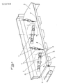
- la figure 1 est une vue en perspective d'une table d'épandage munie de palettes conforme à l'invention ;
- la figure 2 est une vue en élévation d'une palette conforme à l'invention, et
- la figure 3 est une vue en plan d'une palette conforme à l'invention.
- Figure 1 is a perspective view of a spreading table provided with pallets according to the invention;
- FIG. 2 is an elevation view of a pallet according to the invention, and
- Figure 3 is a plan view of a pallet according to the invention.
Conformément à l'invention, la palette 1 présente à chacune de ses deux extrémités longitudinales une plaque articulée 3.According to the invention, the
Comme on peut le voir sur la figure 1, elle est composée de deux cornières 4, fixée de manière connue, par exemple par soudage, sur un axe de rotat ion 5 perpendiculaire à la surface de la table, chaque plaque 3 étant reliée à l'extrémité de chacune des cornières 4, grâce à un moyen d'articulation 6, de telle manière que chaque axe d'articulation 12 soit parallèle à l'axe de rotation des palettes 1.As can be seen in Figure 1, it is composed of two
Selon une caractéristique de l'invention, le moyen d'articulation 6 est sous la forme de trois éléments 7, 8 et 9, dont l'un d'entre eux 7 est au contact des deux autres 8 et 9, de telle sorte que ce moyen 6 ne comporte que deux points de contact 10 et 11 entre les trois éléments 7, 8 et 9 (figure 2). Ainsi, les frottements sont réduits au minimum et la résistance lors de colmatage ou corrosion est diminuée, ce qui est primordial, les palettes 1 travaillant dans un milieu ambiant, tantôt humide, tantôt collant, tantôt agressif.According to a characteristic of the invention, the articulation means 6 is in the form of three
Chaque élément 7, 8 et 9 pourra être avantageusement sous la forme d'un étrier. L'étrier 7 est fixé à la cornière 4 de manière connue, par exemple par soudage, dans un plan vertical selon un axe longitudinal de l'étrier 7, les étriers 8 et 9 étant fixés, quant à eux, à la plaque articulée 3 de manière connue, par exemple par soudage, chacun dans un plan horizontal selon un axe longitudinal de l'étrier 7, et l'un 8 au-dessus de l'ature 9 (figures 2 et 3). Les deux étriers 8 et 9 et donc la plaque 3 sont ainsi maintenus à la palette 1 grâce à l'étrier 7 et la plaque 3 peut, de ce fait, effectuer une rotation d'un angle de 180° suivant un axe d'articulation vertical 12.Each
A chacune des deux extrémités d'une palette 1 se trouve, par conséquent, une plaque 3 mobile autour d'un axe d'articulation vertical 12 parllèle à l'axe de rotation de la palette 1. Ainsi, lors du démarrage, lorsque les palettes 1 sont entraînées en rotation sur une table d'épandage déjà bien remplie de produit, la face active des palettes 1 est moindre, le couple résistant opposé aux palettes 1 est peu élevé et les contraintes sont moindres sur les organes de transmission. De plus, lorsque les palettes ont atteint la vitesse de rotation choisie, les plaques articulées 3 s'étendent sous l'effet de la force centrifuge et confèrent à la palette 1 une longueur complète, les plaques 3 pouvant toutefois s'escamoter par rotation autour de l'axe d'articulation 12 en cas de résistance d'un obstacle, tel qu'un caillou ou un ature corps étranger coincé au niveau de passage d'environ deux centimètres entre la palette 1 et la partie frontale de la table.At each of the two ends of a
Bien entendu, l'invention n'est pas limitée au mode de réalisation décrit et représenté aux dessins annexés. Des modifications restent possibles, notamment du point de vue de la constituion des divers éléments, ou par substitution d'équivalents techniques, sans sortir pour autant du domaine de protection de l'invention. Of course, the invention is not limited to the embodiment described and shown in the accompanying drawings. Modifications remain possible, in particular from the point of view of the constitution of the various elements, or by substitution of technical equivalents, without thereby departing from the scope of protection of the invention.
Claims (5)
Priority Applications (1)
| Application Number | Priority Date | Filing Date | Title |
|---|---|---|---|
| AT87440049T ATE78128T1 (en) | 1986-09-03 | 1987-07-31 | FLAIL FOR SPREADERS. |
Applications Claiming Priority (2)
| Application Number | Priority Date | Filing Date | Title |
|---|---|---|---|
| FR8612459A FR2603155B1 (en) | 1986-09-03 | 1986-09-03 | ARTICULATED PALLET FOR A SPREADING DEVICE |
| FR8612459 | 1986-09-03 |
Publications (2)
| Publication Number | Publication Date |
|---|---|
| EP0263768A1 true EP0263768A1 (en) | 1988-04-13 |
| EP0263768B1 EP0263768B1 (en) | 1992-07-15 |
Family
ID=9338713
Family Applications (1)
| Application Number | Title | Priority Date | Filing Date |
|---|---|---|---|
| EP87440049A Expired - Lifetime EP0263768B1 (en) | 1986-09-03 | 1987-07-31 | Flail beater for a spreader |
Country Status (4)
| Country | Link |
|---|---|
| EP (1) | EP0263768B1 (en) |
| AT (1) | ATE78128T1 (en) |
| DE (1) | DE3780397T2 (en) |
| FR (1) | FR2603155B1 (en) |
Families Citing this family (2)
| Publication number | Priority date | Publication date | Assignee | Title |
|---|---|---|---|---|
| DE4003945C2 (en) * | 1990-02-09 | 1998-08-20 | Amazonen Werke Dreyer H | Centrifugal fertilizer spreader |
| DE29704938U1 (en) * | 1997-03-18 | 1998-08-20 | Kemper Gmbh Maschf | Device for spreading manure or the like. grit |
Citations (4)
| Publication number | Priority date | Publication date | Assignee | Title |
|---|---|---|---|---|
| GB655977A (en) * | 1941-02-24 | 1951-08-08 | Clifford Earl Butler | Improvements in and relating to distributors for fertilisers |
| US3136556A (en) * | 1959-01-14 | 1964-06-09 | Deere & Co | Material unloader with flail beater and hood |
| US3211461A (en) * | 1963-08-16 | 1965-10-12 | Hawk Bilt Mfg Corp | Material unloader |
| FR2284268A1 (en) * | 1974-09-14 | 1976-04-09 | Weichel Ernst | Scatter truck for stable manure - has several horizontal scatter discs arranged below back edge of loading face |
-
1986
- 1986-09-03 FR FR8612459A patent/FR2603155B1/en not_active Expired - Fee Related
-
1987
- 1987-07-31 AT AT87440049T patent/ATE78128T1/en not_active IP Right Cessation
- 1987-07-31 EP EP87440049A patent/EP0263768B1/en not_active Expired - Lifetime
- 1987-07-31 DE DE8787440049T patent/DE3780397T2/en not_active Expired - Fee Related
Patent Citations (4)
| Publication number | Priority date | Publication date | Assignee | Title |
|---|---|---|---|---|
| GB655977A (en) * | 1941-02-24 | 1951-08-08 | Clifford Earl Butler | Improvements in and relating to distributors for fertilisers |
| US3136556A (en) * | 1959-01-14 | 1964-06-09 | Deere & Co | Material unloader with flail beater and hood |
| US3211461A (en) * | 1963-08-16 | 1965-10-12 | Hawk Bilt Mfg Corp | Material unloader |
| FR2284268A1 (en) * | 1974-09-14 | 1976-04-09 | Weichel Ernst | Scatter truck for stable manure - has several horizontal scatter discs arranged below back edge of loading face |
Also Published As
| Publication number | Publication date |
|---|---|
| ATE78128T1 (en) | 1992-08-15 |
| FR2603155A1 (en) | 1988-03-04 |
| FR2603155B1 (en) | 1991-09-27 |
| EP0263768B1 (en) | 1992-07-15 |
| DE3780397D1 (en) | 1992-08-20 |
| DE3780397T2 (en) | 1993-02-18 |
Similar Documents
| Publication | Publication Date | Title |
|---|---|---|
| EP0337909B1 (en) | Mower with direct drive | |
| FR2687039A1 (en) | MOWER WITH IMPROVED LOCKING DEVICE. | |
| EP0461056B1 (en) | Agricultural machine comprising two elements connected by a protected joint | |
| EP1163832B1 (en) | Cutting machine | |
| EP0641157B1 (en) | Machine for the destruction of banana plantation debris | |
| FR2644320A1 (en) | AGRICULTURAL MACHINE WITH AT LEAST ONE ROTOR TO MOVE PRODUCTS ON THE GROUND | |
| EP0263768B1 (en) | Flail beater for a spreader | |
| EP1110442A1 (en) | Cutting element for mower | |
| EP1142468A1 (en) | Haymaking machine | |
| FR2618042A1 (en) | DEVICE FOR SPREADING GRANULAR OR POWDERY MATERIAL | |
| FR2550413A1 (en) | REVERSIBLE ROTARY CULTIVATOR | |
| FR2552616A1 (en) | MACHINE FOR WORKING THE SOIL, PROVIDED WITH A MOTOR | |
| FR2555856A1 (en) | DEVICE FOR SPREADING GRANULAR MATERIAL SUCH AS INGESTED, HERBICIDES, SEEDS, GRAVIERS | |
| FR2558679A1 (en) | ROLLER CONSTRUCTION FOR A SOIL WORKING MACHINE | |
| BE542199A (en) | ||
| FR2748364A1 (en) | Clearing machine for vegetation | |
| FR2733115A1 (en) | Rotary cutter for vegetation, | |
| BE516389A (en) | ||
| EP0611237B1 (en) | Soil working machine, especially disc harrow, with reduced transport width and adjustable position of the working tool | |
| EP0499556A1 (en) | Agricultural soil working machine with an improved share for the lateral stabilization | |
| EP0307334B1 (en) | Soil working machine comprising shares and a rotor | |
| BE342194A (en) | ||
| FR2677216A1 (en) | IMPROVED MOWER. | |
| FR2729816A1 (en) | Towing device for agricultural tractor | |
| EP0346255B1 (en) | Soilworking machine provided with shares and a rotor |
Legal Events
| Date | Code | Title | Description |
|---|---|---|---|
| PUAI | Public reference made under article 153(3) epc to a published international application that has entered the european phase |
Free format text: ORIGINAL CODE: 0009012 |
|
| AK | Designated contracting states |
Kind code of ref document: A1 Designated state(s): AT BE CH DE LI LU NL |
|
| 17P | Request for examination filed |
Effective date: 19881011 |
|
| 17Q | First examination report despatched |
Effective date: 19900625 |
|
| GRAA | (expected) grant |
Free format text: ORIGINAL CODE: 0009210 |
|
| AK | Designated contracting states |
Kind code of ref document: B1 Designated state(s): AT BE CH DE LI LU NL |
|
| REF | Corresponds to: |
Ref document number: 78128 Country of ref document: AT Date of ref document: 19920815 Kind code of ref document: T |
|
| REF | Corresponds to: |
Ref document number: 3780397 Country of ref document: DE Date of ref document: 19920820 |
|
| PGFP | Annual fee paid to national office [announced via postgrant information from national office to epo] |
Ref country code: CH Payment date: 19920922 Year of fee payment: 6 |
|
| PGFP | Annual fee paid to national office [announced via postgrant information from national office to epo] |
Ref country code: DE Payment date: 19930325 Year of fee payment: 6 |
|
| REG | Reference to a national code |
Ref country code: CH Ref legal event code: PUE Owner name: HEYWANG INDUSTRIE, SOCIETE ANONYME |
|
| PLBE | No opposition filed within time limit |
Free format text: ORIGINAL CODE: 0009261 |
|
| STAA | Information on the status of an ep patent application or granted ep patent |
Free format text: STATUS: NO OPPOSITION FILED WITHIN TIME LIMIT |
|
| 26N | No opposition filed | ||
| PG25 | Lapsed in a contracting state [announced via postgrant information from national office to epo] |
Ref country code: LI Effective date: 19930731 Ref country code: CH Effective date: 19930731 |
|
| NLS | Nl: assignments of ep-patents |
Owner name: HEYWANG INDUSTRIES, SOCIETE ANONYME TE BOURGHEIM, |
|
| REG | Reference to a national code |
Ref country code: CH Ref legal event code: PL |
|
| PG25 | Lapsed in a contracting state [announced via postgrant information from national office to epo] |
Ref country code: DE Effective date: 19940401 |
|
| EPTA | Lu: last paid annual fee | ||
| PGFP | Annual fee paid to national office [announced via postgrant information from national office to epo] |
Ref country code: AT Payment date: 19970721 Year of fee payment: 11 |
|
| PGFP | Annual fee paid to national office [announced via postgrant information from national office to epo] |
Ref country code: BE Payment date: 19970729 Year of fee payment: 11 |
|
| PGFP | Annual fee paid to national office [announced via postgrant information from national office to epo] |
Ref country code: LU Payment date: 19970730 Year of fee payment: 11 |
|
| PGFP | Annual fee paid to national office [announced via postgrant information from national office to epo] |
Ref country code: NL Payment date: 19970731 Year of fee payment: 11 |
|
| PG25 | Lapsed in a contracting state [announced via postgrant information from national office to epo] |
Ref country code: LU Free format text: LAPSE BECAUSE OF NON-PAYMENT OF DUE FEES Effective date: 19980731 Ref country code: BE Free format text: LAPSE BECAUSE OF NON-PAYMENT OF DUE FEES Effective date: 19980731 Ref country code: AT Free format text: LAPSE BECAUSE OF NON-PAYMENT OF DUE FEES Effective date: 19980731 |
|
| BERE | Be: lapsed |
Owner name: S.A. HEYWANG INDUSTRIE Effective date: 19980731 |
|
| PG25 | Lapsed in a contracting state [announced via postgrant information from national office to epo] |
Ref country code: NL Free format text: LAPSE BECAUSE OF NON-PAYMENT OF DUE FEES Effective date: 19990201 |
|
| NLV4 | Nl: lapsed or anulled due to non-payment of the annual fee |
Effective date: 19990201 |