EP0263661B1 - Treating structural cellular materials - Google Patents
Treating structural cellular materials Download PDFInfo
- Publication number
- EP0263661B1 EP0263661B1 EP87308800A EP87308800A EP0263661B1 EP 0263661 B1 EP0263661 B1 EP 0263661B1 EP 87308800 A EP87308800 A EP 87308800A EP 87308800 A EP87308800 A EP 87308800A EP 0263661 B1 EP0263661 B1 EP 0263661B1
- Authority
- EP
- European Patent Office
- Prior art keywords
- conveyor
- expanded
- sheets
- sheet
- expander unit
- Prior art date
- Legal status (The legal status is an assumption and is not a legal conclusion. Google has not performed a legal analysis and makes no representation as to the accuracy of the status listed.)
- Expired - Lifetime
Links
Images


Classifications
-
- B—PERFORMING OPERATIONS; TRANSPORTING
- B32—LAYERED PRODUCTS
- B32B—LAYERED PRODUCTS, i.e. PRODUCTS BUILT-UP OF STRATA OF FLAT OR NON-FLAT, e.g. CELLULAR OR HONEYCOMB, FORM
- B32B37/00—Methods or apparatus for laminating, e.g. by curing or by ultrasonic bonding
- B32B37/14—Methods or apparatus for laminating, e.g. by curing or by ultrasonic bonding characterised by the properties of the layers
- B32B37/146—Methods or apparatus for laminating, e.g. by curing or by ultrasonic bonding characterised by the properties of the layers whereby one or more of the layers is a honeycomb structure
-
- B—PERFORMING OPERATIONS; TRANSPORTING
- B29—WORKING OF PLASTICS; WORKING OF SUBSTANCES IN A PLASTIC STATE IN GENERAL
- B29D—PRODUCING PARTICULAR ARTICLES FROM PLASTICS OR FROM SUBSTANCES IN A PLASTIC STATE
- B29D24/00—Producing articles with hollow walls
- B29D24/002—Producing articles with hollow walls formed with structures, e.g. cores placed between two plates or sheets, e.g. partially filled
- B29D24/005—Producing articles with hollow walls formed with structures, e.g. cores placed between two plates or sheets, e.g. partially filled the structure having joined ribs, e.g. honeycomb
Definitions
- This invention relates to the treatment of structural cellular materials, particularly in connection with the manufacture of honeycomb filled panels.
- Honeycomb filled panels are used in a wide variety of applications. They consist generally of two sheets of facing material and, sandwiched between the two sheets of facing material and filling the interspace between them, an expanded structural cellular material, e.g. honeycomb material.
- the honeycomb is conventionally formed of card or like material and is adhered to the inwardly facing faces of the two sheets of facing material.
- the panel may include, if desired, one or more edge members located between the sheets of facing material.
- a major use of such panels is as doors, consisting of two sheets of facing material, four edge members, and a cellular filling.
- the structural cellular material used is conventionally made of card and, until it is adhered in position between the two sheets of facing material, is a relatively unstable material dimensionally. It also takes up a lot of space in its expanded form and is accordingly normally manufactured and stored in unexpanded form and expanded just prior to use. Machinery for effecting such expansion is known and is described, for example, in GB-A-1355642 and GB-A-1596848.
- the machinery for effecting expansion relies on the physical properties of the material from which the structural cellular material is made, which is most commonly card stock.
- Such card stock can take a permanent set or crease when appropriately manipulated.
- the unexpanded material in its "as manufactured” state is pulled out in an expansion direction to a degree sufficient to give a permanent set to the card, so that from a dimensionally unstable unexpanded form, there is produced a relatively dimensionally stable expanded cellular unit. It is still capable of being compressed or expanded in any direction in the general plane of the expanded unit, but does not tend elastically to return to the unexpanded state.
- a piece of such expanded stabilised honeycomb material is taken from the output table and placed on top of one of the two outer sheets.
- the second outer sheet is then placed on top of the stabilised honeycomb unit, and the assembly compressed together, optionally with the application of heat, to consolidate the unit and cure or dry the adhesive.
- the adhesive is conventionally provided on the sheets, though it is known to apply adhesive to the edges of the cells of the stabilised expanded honeycomb material.
- GB-A-783362 and US-A-3139369 and 3510381 disclose making cellular fill panels by means including moving one of the outer skins along a conveyor, coating it with glue, moving the honeycomb material in a direction transverse to the conveyor to a position on top of the outer skin and moving a glued second outer skin in a direction transverse to the conveyor to a position on the honeycomb. This takes up a lot of space.
- US-A-3510381 describes a likewise space consumptive arrangement of two adjacent conveyors. A glued top panel is moved along by one conveyor, and transferred across to a double deck conveyor on which it is assembled with a honeycomb core on top of a bottom panel.
- US-A-3166838 discloses a method of securing a sheet of flexible material, e.g. waterproof paper, to one side of a relatively thin sheet of expanded metal without the use of adhesive.
- the sheet is introduced from above the cellular expanded metal sheet, and pieces of the expanded metal are punched out and bent over to hold the sheet on.
- the present invention provides apparatus for the treatment of unexpanded structural cellular material comprising a first conveyor for feeding a sequence of sheets through the apparatus, an expander unit in which the unexpanded structural cellular material is expanded, and a second conveyor which feeds unexpanded material to the expander unit and a combining station through which the sheets are conveyed on the first conveyor in a straight line and in which the expanded material is fed at an acute angle onto the sheets and which further includes a rotatably driven brush, for combining the expanded material with the sheets, the peripheral speed of the brush being substantially equal to the linear speed of the first conveyor, and including synchronizing means provided for synchronizing the combination of the expanded material with the sheets.
- apparatus for the treatment of unexpanded structural cellular material e.g. for the manufacture of panels
- apparatus includes a first conveyor adapted to pass a sequence of sheets of material through a combining station in a straight line, a second conveyor upstream and above the combining station adapted to feed unexpanded structural cellular material to an expander unit located above the first conveyor, the outfeed from the expander unit including a cutter adapted to cut expanded structural cellular material into sections and positioned just above the first conveyor, and adapted to feed such expanded material at an acute angle on to a sheet conveyed by the first conveyor, and, at the combining station, a brush for combining a piece of expanded cellular material with the sheets of material, and rotatably drivable such that its peripheral speed at least substantially matches the linear speed of the first conveyor, and the apparatus including means for synchronizing the movement of the series of sheets along the first conveyor with the operation of the expander unit and its cutter whereby to synchronize the arrival of
- Apparatus operating in this way enables honeycomb material shipped and stored in unexpanded form to be expanded, cut into sections of appropriate size and those sections located relative to a facing sheet in one continuous operation.
- the apparatus may include a further station downstream of the combining station at which a second sheet is applied to the top of the expanded material, the sandwich assemblies so formed then being stacked compressed and dried or cured to form the final panels.
- the brush which preferably extends over the whole width of the first conveyor, is preferably a fairly stiff bristle brush, e.g. of fairly stiff nylon bristles, and is preferably of diameter 4 to 10 times the thickness of the expanded material.
- the angle at which the expanded cellular material is fed onto the sheet from the expander unit is preferably within the range of 20 to 35°, most preferably about 30°.
- the preferred way of ensuring synchronism between the production of the expanded material and the arrival of a sheet at the combining station is to provide a trip switch on the first conveyor operated by the leading edge of the sheet as it comes towards the combining station. By appropriately positioning this upstream of the combining station, it can be ensured that the expanded material and the sheet are combined appropriately together.
- the sheets conveyed by the first conveyor may be plain, or they may have one or more upstanding edge members thereon.
- each sheet may have four edge members, the sheet and the edge members constituting a tray into which the expanded structural cellular material section is placed.
- trays 1 each formed of a frame and base sheet, are fed sequentially along a main conveyor 10. They pass below a honeycomb storage area denoted 12 on which e.g. a pallet 14 may be placed carrying a sinuous stack of unexpanded honeycomb material 16. They then pass under an expander and cutter unit 2 having an infeed table 4, an expansion section and a cutter (both not shown). Expanded honeycomb sections emerge from the unit 2 at an angle and just above the main conveyor 10. Immediately downstream of the unit 2, a rotary brush 6 is provided. The brush 6 acts to combine together a piece of expanded honeycomb material 8 which is coming from the expander and a tray 1 which passes through the combining station. The filled tray 9 then passes further along the conveyor to a position in which a sheet of e.g. plywood is placed on top of it and a stack of the items so formed then passes to an appropriate station for compression and curing.
- a honeycomb storage area denoted 12 on which e.g. a pallet 14 may be placed carrying a sinuous stack of
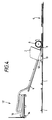
- this shows the expander and cutter unit 2 in diagrammatic side view. It consists basically of an inclined infeed table 4 having at its upstream end a roller 20 over which unexpanded material may pass, and a driving and cutting section 22 including a pair of opposed rollers 23,24 (only roller 23 being shown) which engage the bottom and top side of the honeycomb material respectively and pull it down the infeed table 4 and push it out via an outlet orifice located just above the main conveyor.
- Mounted on the infeed table 4 in known fashion is a pair of fences 25 which define a V-shape tapering towards a narrow throat just upstream of the pair of drive rollers 23,24.
- One or more freely rotatable captive bars 26 rests on the top of the honeycomb material 30 as it moves down the table to impart stability.
- the honeycomb is compressed transversely to its expansion direction as it passes down the table, and as it passes through the throat the material acquires adequate permanent set such that when the material emerges from the throat, it expands laterally to give a web 8 of stabilised expanded honeycomb material.
- a pneumatically operated guillotine blade 35 (see Figure 3) is located at the outlet. This is actuated at an appropriate time to chop off a section of the expanded material. This time is chosen such that the rear end of the section of material so formed coincides with the rear end of the tray cavity.
- the feed is driven by an electric motor 32 connected via a chain drive 33 to one of the two drive rollers.
- the upper drive roller 24 is mounted on a frame 36 which can be swung by a first hydraulic cylinder 38 from the downward position shown in Figure 2 to an upper position in which the upper roller 24 is spaced from the lower roller 23 sufficiently to enable the leading edge of honeycomb to be passed through the gap when setting up.
- a second hydraulic cylinder 40 operates, via a series of crank arms, the guillotine blade 35 which is set to reciprocate vertically on a pair of pillars 46 and to cut off the expanded honeycomb material when desired. Operation in synchronism with the feed of trays 1 is effected by means of a tripswitch 50 connected to appropriate control mechanisms.
Abstract
Description
- This invention relates to the treatment of structural cellular materials, particularly in connection with the manufacture of honeycomb filled panels.
- Honeycomb filled panels are used in a wide variety of applications. They consist generally of two sheets of facing material and, sandwiched between the two sheets of facing material and filling the interspace between them, an expanded structural cellular material, e.g. honeycomb material. The honeycomb is conventionally formed of card or like material and is adhered to the inwardly facing faces of the two sheets of facing material. The panel may include, if desired, one or more edge members located between the sheets of facing material.
- A major use of such panels is as doors, consisting of two sheets of facing material, four edge members, and a cellular filling.
- The structural cellular material used is conventionally made of card and, until it is adhered in position between the two sheets of facing material, is a relatively unstable material dimensionally. It also takes up a lot of space in its expanded form and is accordingly normally manufactured and stored in unexpanded form and expanded just prior to use. Machinery for effecting such expansion is known and is described, for example, in GB-A-1355642 and GB-A-1596848.
- The machinery for effecting expansion relies on the physical properties of the material from which the structural cellular material is made, which is most commonly card stock. Such card stock can take a permanent set or crease when appropriately manipulated. In the machinery, as explained in the above specifications, the unexpanded material in its "as manufactured" state is pulled out in an expansion direction to a degree sufficient to give a permanent set to the card, so that from a dimensionally unstable unexpanded form, there is produced a relatively dimensionally stable expanded cellular unit. It is still capable of being compressed or expanded in any direction in the general plane of the expanded unit, but does not tend elastically to return to the unexpanded state.
- Conventionally such machinery has an output table or conveyor onto which such an expanded stabilised piece of honeycomb material is ejected and from which it is then manually removed.
- In order to produce a panel, a piece of such expanded stabilised honeycomb material is taken from the output table and placed on top of one of the two outer sheets. The second outer sheet is then placed on top of the stabilised honeycomb unit, and the assembly compressed together, optionally with the application of heat, to consolidate the unit and cure or dry the adhesive. The adhesive is conventionally provided on the sheets, though it is known to apply adhesive to the edges of the cells of the stabilised expanded honeycomb material.
- The manual operation of placing the material in position is time consuming and requires skilled labour. Even if the panels have edge members, so that the honeycomb needs only to be placed in a tray formed by the edge members and one facing sheet, the operation is labour intensive.
- Mechanical means for producing honeycomb cored panels are known and are described, for example, in GB-A-783362 and US-A-3139369 and 3510381. GB-A-783362 and US-A-3139369 both disclose making cellular fill panels by means including moving one of the outer skins along a conveyor, coating it with glue, moving the honeycomb material in a direction transverse to the conveyor to a position on top of the outer skin and moving a glued second outer skin in a direction transverse to the conveyor to a position on the honeycomb. This takes up a lot of space.
- US-A-3510381 describes a likewise space consumptive arrangement of two adjacent conveyors. A glued top panel is moved along by one conveyor, and transferred across to a double deck conveyor on which it is assembled with a honeycomb core on top of a bottom panel.
- US-A-3166838 discloses a method of securing a sheet of flexible material, e.g. waterproof paper, to one side of a relatively thin sheet of expanded metal without the use of adhesive. The sheet is introduced from above the cellular expanded metal sheet, and pieces of the expanded metal are punched out and bent over to hold the sheet on.
- In one aspect, the present invention provides apparatus for the treatment of unexpanded structural cellular material comprising a first conveyor for feeding a sequence of sheets through the apparatus, an expander unit in which the unexpanded structural cellular material is expanded, and a second conveyor which feeds unexpanded material to the expander unit and a combining station through which the sheets are conveyed on the first conveyor in a straight line and in which the expanded material is fed at an acute angle onto the sheets and which further includes a rotatably driven brush, for combining the expanded material with the sheets, the peripheral speed of the brush being substantially equal to the linear speed of the first conveyor, and including synchronizing means provided for synchronizing the combination of the expanded material with the sheets.
- In a further aspect of the present invention there is provided apparatus for the treatment of unexpanded structural cellular material, e.g. for the manufacture of panels, which apparatus includes a first conveyor adapted to pass a sequence of sheets of material through a combining station in a straight line, a second conveyor upstream and above the combining station adapted to feed unexpanded structural cellular material to an expander unit located above the first conveyor, the outfeed from the expander unit including a cutter adapted to cut expanded structural cellular material into sections and positioned just above the first conveyor, and adapted to feed such expanded material at an acute angle on to a sheet conveyed by the first conveyor, and, at the combining station, a brush for combining a piece of expanded cellular material with the sheets of material, and rotatably drivable such that its peripheral speed at least substantially matches the linear speed of the first conveyor, and the apparatus including means for synchronizing the movement of the series of sheets along the first conveyor with the operation of the expander unit and its cutter whereby to synchronize the arrival of a leading edge of a piece of expanded cellular material emerging from the expander unit relative to the leading edge of the sheet and to cut the expanded material at a point such that the length of expanded material corresponds to the length of the sheet measured in the direction of movement of the first conveyor.
- Apparatus operating in this way enables honeycomb material shipped and stored in unexpanded form to be expanded, cut into sections of appropriate size and those sections located relative to a facing sheet in one continuous operation. The apparatus may include a further station downstream of the combining station at which a second sheet is applied to the top of the expanded material, the sandwich assemblies so formed then being stacked compressed and dried or cured to form the final panels.
- The brush, which preferably extends over the whole width of the first conveyor, is preferably a fairly stiff bristle brush, e.g. of fairly stiff nylon bristles, and is preferably of diameter 4 to 10 times the thickness of the expanded material.
- The angle at which the expanded cellular material is fed onto the sheet from the expander unit, which generally conveniently corresponds to the angle between the second conveyor and the first conveyor, is preferably within the range of 20 to 35°, most preferably about 30°.
- The preferred way of ensuring synchronism between the production of the expanded material and the arrival of a sheet at the combining station is to provide a trip switch on the first conveyor operated by the leading edge of the sheet as it comes towards the combining station. By appropriately positioning this upstream of the combining station, it can be ensured that the expanded material and the sheet are combined appropriately together.
- The sheets conveyed by the first conveyor may be plain, or they may have one or more upstanding edge members thereon. For example, for making doors, each sheet may have four edge members, the sheet and the edge members constituting a tray into which the expanded structural cellular material section is placed.
- The invention is illustrated by way of example with reference to the accompanying drawings in which:
- Figure 1 is a diagrammatic side view of apparatus in accordance with the present invention,
- Figure 2 is a diagrammatic front view of the honeycomb expander and cutter unit shown in Figure 1,
- Figure 3 is a side view of the expander and cutter unit shown in Figure 2, and
- Figure 4 is a general arrangement drawing showing the overall sequence of operations.
- Referring initially to Figure 4, trays 1, each formed of a frame and base sheet, are fed sequentially along a
main conveyor 10. They pass below a honeycomb storage area denoted 12 on which e.g. apallet 14 may be placed carrying a sinuous stack ofunexpanded honeycomb material 16. They then pass under an expander andcutter unit 2 having an infeed table 4, an expansion section and a cutter (both not shown). Expanded honeycomb sections emerge from theunit 2 at an angle and just above themain conveyor 10. Immediately downstream of theunit 2, a rotary brush 6 is provided. The brush 6 acts to combine together a piece of expandedhoneycomb material 8 which is coming from the expander and a tray 1 which passes through the combining station. The filledtray 9 then passes further along the conveyor to a position in which a sheet of e.g. plywood is placed on top of it and a stack of the items so formed then passes to an appropriate station for compression and curing. - Referring now in detail to Figure 1, this shows the expander and
cutter unit 2 in diagrammatic side view. It consists basically of an inclined infeed table 4 having at its upstream end aroller 20 over which unexpanded material may pass, and a driving and cutting section 22 including a pair ofopposed rollers 23,24 (onlyroller 23 being shown) which engage the bottom and top side of the honeycomb material respectively and pull it down the infeed table 4 and push it out via an outlet orifice located just above the main conveyor. Mounted on the infeed table 4 in known fashion is a pair offences 25 which define a V-shape tapering towards a narrow throat just upstream of the pair ofdrive rollers captive bars 26 rests on the top of thehoneycomb material 30 as it moves down the table to impart stability. The honeycomb is compressed transversely to its expansion direction as it passes down the table, and as it passes through the throat the material acquires adequate permanent set such that when the material emerges from the throat, it expands laterally to give aweb 8 of stabilised expanded honeycomb material. A pneumatically operated guillotine blade 35 (see Figure 3) is located at the outlet. This is actuated at an appropriate time to chop off a section of the expanded material. This time is chosen such that the rear end of the section of material so formed coincides with the rear end of the tray cavity. - Referring to Figures 2 and 3, the internal structure of the feed and cutter mechanism is shown. The feed is driven by an
electric motor 32 connected via achain drive 33 to one of the two drive rollers. Theupper drive roller 24 is mounted on aframe 36 which can be swung by a firsthydraulic cylinder 38 from the downward position shown in Figure 2 to an upper position in which theupper roller 24 is spaced from thelower roller 23 sufficiently to enable the leading edge of honeycomb to be passed through the gap when setting up. - A second
hydraulic cylinder 40 operates, via a series of crank arms, theguillotine blade 35 which is set to reciprocate vertically on a pair ofpillars 46 and to cut off the expanded honeycomb material when desired. Operation in synchronism with the feed of trays 1 is effected by means of atripswitch 50 connected to appropriate control mechanisms.
Claims (14)
- Apparatus for the treatment of unexpanded structural cellular material comprising a first conveyor (10) for feeding a sequence of sheets (1) through the apparatus, an expander unit (2) in which the unexpanded structural cellular material (30) is expanded, and a second conveyor (4) which feeds unexpanded material to the expander unit, and a combining station through which the sheets (1) are conveyed on the first conveyor (10) in a straight line and in which the expanded material (8) is fed at an acute angle onto the sheets (1) and which further includes a rotatably driven brush (6), for combining the expanded material (8) with the sheets (1), the peripheral speed of the brush (6) being substantially equal to the linear speed of the first conveyor (10), and including synchronising means (50) provided for synchronizing the combination of the expanded material (8) with the sheets (1).
- Apparatus according to claim 1, and characterised by a cutter (35) for cutting the expanded structural cellular material into lengths corresponding to the length of the sheets (1) measured in the direction of movement of the first conveyor (10).
- Apparatus according to claim 2, characterised in that the synchronizing means (50) is a tripswitch attached to the expander unit (2) which operates the cutter (35) on the arrival of a leading edge of a sheet (1) under the unit (2).
- Apparatus according to claim 2 or 3, wherein the cutter (35) is actuated by a hydraulic cylinder (40) via a series of crank arms, the cutter reciprocating vertically on a pair of pillars (46).
- Apparatus according to any one of claims 1 to 4, wherein the brush (6) extends over the whole width of the first conveyor (10), and is a bristle brush having a diameter of between four and ten times the thickness of the expanded material.
- Apparatus according to any one of claims 1 to 5, wherein the expanded mateerial (8) is fed onto the sheets (1) from the expander unit (2) at an angle in the range of 20° to 35°.
- Apparatus according to claim 6, wherein the angle is about 30°.
- Apparatus according to claim 6 or 7, wherein the angle corresponds to the angle between the first conveyor (10) and the second conveyor (4).
- Apparatus according to any one of claims 1 to 8, wherein the sheets (1) are plain.
- Apparatus according to any one of claims 1 to 8, wherein the sheets (1) having one or more upstanding edge members.
- Apparatus according to any one of the preceding claims, wherein the expander unit (2) includes drive means (23,24).
- Apparatus according to claim 11, wherein the drive means (23,24) comprise two rollers, one of which is driven by an electric motor (32) via a chain drive (33).
- Apparatus according to any one of the preceding claims, including a further station downstream of the combining station at which a second sheet is applied to the top of the expanded material (8), the sandwich assemblies so formed then being stacked compressed and dried or cured to form the final panels.
- Apparatus for the treatment of unexpanded structural cellular material, e.g. for the manufacture of panels, which apparatus includes a first conveyor (10) adapted to pass a sequence of sheets (1) of material through a combining station in a straight line, a second conveyor (4) upstream and above the combining station adapted to feed unexpanded structural cellular material to an expander unit (2) located above the first conveyor (10), the outfeed from the expander unit including a cutter (35) adapted to cut expanded structural cellular material into sections and positioned just above the first conveyor (10), and adapted to feed such expanded material at an acute angle on to a sheet (1) conveyed by the first conveyor, and, at the combining station, a brush (6) for combining a piece of expanded cellular material (8) with the sheets (1) of material and rotatably drivable such that its peripheral speed at least substantially matches the linear speed of the first conveyor (10), and the apparatus including means (50) for synchronizing the movement of the series of sheets along the first conveyor (10) with the operation of the expander unit (2) and its cutter whereby to synchronize the arrival of a leading edge of a piece of expanded cellular material (8) emerging from the expander unit (2) relative to the leading edge of the sheet and to cut the expanded material at a point such that the length of expanded material corresponds to the length of the sheet measured in the direction of movement of the first conveyor (10).
Priority Applications (1)
| Application Number | Priority Date | Filing Date | Title |
|---|---|---|---|
| AT87308800T ATE71581T1 (en) | 1986-10-06 | 1987-10-05 | TREATMENT OF STRUCTURED CELL MATERIAL. |
Applications Claiming Priority (2)
| Application Number | Priority Date | Filing Date | Title |
|---|---|---|---|
| GB8623941 | 1986-10-06 | ||
| GB868623941A GB8623941D0 (en) | 1986-10-06 | 1986-10-06 | Treating structural cellular materials |
Publications (3)
| Publication Number | Publication Date |
|---|---|
| EP0263661A2 EP0263661A2 (en) | 1988-04-13 |
| EP0263661A3 EP0263661A3 (en) | 1989-08-16 |
| EP0263661B1 true EP0263661B1 (en) | 1992-01-15 |
Family
ID=10605325
Family Applications (1)
| Application Number | Title | Priority Date | Filing Date |
|---|---|---|---|
| EP87308800A Expired - Lifetime EP0263661B1 (en) | 1986-10-06 | 1987-10-05 | Treating structural cellular materials |
Country Status (8)
| Country | Link |
|---|---|
| EP (1) | EP0263661B1 (en) |
| AT (1) | ATE71581T1 (en) |
| DE (1) | DE3776058D1 (en) |
| DK (1) | DK166571B1 (en) |
| ES (1) | ES2028098T3 (en) |
| FI (1) | FI87548C (en) |
| GB (1) | GB8623941D0 (en) |
| NO (1) | NO175295C (en) |
Families Citing this family (2)
| Publication number | Priority date | Publication date | Assignee | Title |
|---|---|---|---|---|
| DE102005057550A1 (en) | 2005-11-30 | 2007-06-21 | Fritz Egger Gmbh & Co. | Method and device for producing a lightweight board and lightweight board |
| US9055906B2 (en) | 2006-06-14 | 2015-06-16 | Intuitive Surgical Operations, Inc. | In-vivo visualization systems |
Family Cites Families (4)
| Publication number | Priority date | Publication date | Assignee | Title |
|---|---|---|---|---|
| GB783362A (en) * | 1955-06-10 | 1957-09-25 | Isoleringsaktiebolaget Wmb | Improvements in or relating to structural building panel units |
| US3139369A (en) * | 1960-08-03 | 1964-06-30 | Lockheed Aircraft Corp | Apparatus for making laminated building panels of cellular structure |
| US3166838A (en) * | 1962-04-02 | 1965-01-26 | Western Metal Lath Co | Method of securing expanded metal to thin pliable material |
| US3510381A (en) * | 1966-03-11 | 1970-05-05 | Reynolds Metals Co | Apparatus and method for making laminated panel means |
-
1986
- 1986-10-06 GB GB868623941A patent/GB8623941D0/en active Pending
-
1987
- 1987-10-02 FI FI874338A patent/FI87548C/en not_active IP Right Cessation
- 1987-10-05 NO NO874174A patent/NO175295C/en unknown
- 1987-10-05 DK DK520887A patent/DK166571B1/en not_active IP Right Cessation
- 1987-10-05 EP EP87308800A patent/EP0263661B1/en not_active Expired - Lifetime
- 1987-10-05 ES ES198787308800T patent/ES2028098T3/en not_active Expired - Lifetime
- 1987-10-05 DE DE8787308800T patent/DE3776058D1/en not_active Expired - Fee Related
- 1987-10-05 AT AT87308800T patent/ATE71581T1/en not_active IP Right Cessation
Also Published As
| Publication number | Publication date |
|---|---|
| NO874174D0 (en) | 1987-10-05 |
| ATE71581T1 (en) | 1992-02-15 |
| DK166571B1 (en) | 1993-06-14 |
| EP0263661A3 (en) | 1989-08-16 |
| NO874174L (en) | 1988-04-07 |
| DK520887A (en) | 1988-04-07 |
| FI87548B (en) | 1992-10-15 |
| DE3776058D1 (en) | 1992-02-27 |
| EP0263661A2 (en) | 1988-04-13 |
| NO175295B (en) | 1994-06-20 |
| ES2028098T3 (en) | 1992-07-01 |
| NO175295C (en) | 1994-10-05 |
| FI874338A (en) | 1988-04-07 |
| GB8623941D0 (en) | 1986-11-12 |
| FI87548C (en) | 1993-01-25 |
| FI874338A0 (en) | 1987-10-02 |
| DK520887D0 (en) | 1987-10-05 |
Similar Documents
| Publication | Publication Date | Title |
|---|---|---|
| US4581186A (en) | Method of making foam core building panels in a continuous operation | |
| CA2343583A1 (en) | A process for cutting out panels or the like | |
| US4849039A (en) | Method and apparatus for manufacturing blind material | |
| US4602466A (en) | Foam building panels | |
| US5913766A (en) | Apparatus and method for crushing a honey comb panel | |
| US4606715A (en) | Apparatus for making building panels in a continuous operation | |
| US3257253A (en) | Laminated cellular panel | |
| EP2298517A1 (en) | Apparatus for preparing a panel for edgebanding | |
| US3360420A (en) | Apparatus for forming shaped cushions | |
| US2991214A (en) | Method of manufacturing composite paper and veneer sheet material | |
| EP0507733A1 (en) | Apparatus for cutting and stacking sheets | |
| JPS6328755B2 (en) | ||
| ITVE940023A1 (en) | MINERAL WOOL PANEL AND PROCEDURE FOR ITS REALIZATION. | |
| EP0263661B1 (en) | Treating structural cellular materials | |
| US3413177A (en) | Apparatus for making laminated cellular panel | |
| US3347136A (en) | Process and arrangement for production and placing of filling material in hollow building elements | |
| US1946056A (en) | Apparatus for forming wall board into bundles | |
| US1945306A (en) | Machine and method for producing wall board | |
| GB1036126A (en) | Improvements in or relating to the manufacture of cellular structural materials | |
| US4986864A (en) | Page binding method and machine | |
| US4466787A (en) | Apparatus for forming support device | |
| US6915572B1 (en) | Method and plant for continuously producing construction | |
| KR101768496B1 (en) | A auto roll trimming device | |
| US3741840A (en) | Method for producing continuous compressed honeycomb | |
| US3630801A (en) | Machine for producing continuous compressed honeycomb |
Legal Events
| Date | Code | Title | Description |
|---|---|---|---|
| PUAI | Public reference made under article 153(3) epc to a published international application that has entered the european phase |
Free format text: ORIGINAL CODE: 0009012 |
|
| AK | Designated contracting states |
Kind code of ref document: A2 Designated state(s): AT BE CH DE ES FR GB GR IT LI LU NL SE |
|
| PUAL | Search report despatched |
Free format text: ORIGINAL CODE: 0009013 |
|
| AK | Designated contracting states |
Kind code of ref document: A3 Designated state(s): AT BE CH DE ES FR GB GR IT LI LU NL SE |
|
| 17P | Request for examination filed |
Effective date: 19890825 |
|
| 17Q | First examination report despatched |
Effective date: 19900910 |
|
| GRAA | (expected) grant |
Free format text: ORIGINAL CODE: 0009210 |
|
| STAA | Information on the status of an ep patent application or granted ep patent |
Free format text: STATUS: THE PATENT HAS BEEN GRANTED |
|
| AK | Designated contracting states |
Kind code of ref document: B1 Designated state(s): AT BE CH DE ES FR GB GR IT LI LU NL SE |
|
| PG25 | Lapsed in a contracting state [announced via postgrant information from national office to epo] |
Ref country code: LI Effective date: 19920115 Ref country code: GR Free format text: LAPSE BECAUSE OF FAILURE TO SUBMIT A TRANSLATION OF THE DESCRIPTION OR TO PAY THE FEE WITHIN THE PRESCRIBED TIME-LIMIT Effective date: 19920115 Ref country code: CH Effective date: 19920115 Ref country code: AT Effective date: 19920115 |
|
| REF | Corresponds to: |
Ref document number: 71581 Country of ref document: AT Date of ref document: 19920215 Kind code of ref document: T |
|
| ITF | It: translation for a ep patent filed |
Owner name: BARZANO' E ZANARDO MILANO S.P.A. |
|
| REF | Corresponds to: |
Ref document number: 3776058 Country of ref document: DE Date of ref document: 19920227 |
|
| ET | Fr: translation filed | ||
| REG | Reference to a national code |
Ref country code: CH Ref legal event code: PL |
|
| REG | Reference to a national code |
Ref country code: ES Ref legal event code: FG2A Ref document number: 2028098 Country of ref document: ES Kind code of ref document: T3 |
|
| PG25 | Lapsed in a contracting state [announced via postgrant information from national office to epo] |
Ref country code: LU Free format text: LAPSE BECAUSE OF NON-PAYMENT OF DUE FEES Effective date: 19921031 |
|
| PLBE | No opposition filed within time limit |
Free format text: ORIGINAL CODE: 0009261 |
|
| 26N | No opposition filed | ||
| PGFP | Annual fee paid to national office [announced via postgrant information from national office to epo] |
Ref country code: GB Payment date: 19940817 Year of fee payment: 8 |
|
| PGFP | Annual fee paid to national office [announced via postgrant information from national office to epo] |
Ref country code: FR Payment date: 19940825 Year of fee payment: 8 |
|
| PGFP | Annual fee paid to national office [announced via postgrant information from national office to epo] |
Ref country code: BE Payment date: 19940826 Year of fee payment: 8 |
|
| PGFP | Annual fee paid to national office [announced via postgrant information from national office to epo] |
Ref country code: ES Payment date: 19940912 Year of fee payment: 8 |
|
| PGFP | Annual fee paid to national office [announced via postgrant information from national office to epo] |
Ref country code: SE Payment date: 19940928 Year of fee payment: 8 |
|
| PGFP | Annual fee paid to national office [announced via postgrant information from national office to epo] |
Ref country code: DE Payment date: 19941018 Year of fee payment: 8 |
|
| PGFP | Annual fee paid to national office [announced via postgrant information from national office to epo] |
Ref country code: NL Payment date: 19941031 Year of fee payment: 8 |
|
| EAL | Se: european patent in force in sweden |
Ref document number: 87308800.9 |
|
| PG25 | Lapsed in a contracting state [announced via postgrant information from national office to epo] |
Ref country code: GB Effective date: 19951005 |
|
| PG25 | Lapsed in a contracting state [announced via postgrant information from national office to epo] |
Ref country code: SE Effective date: 19951006 Ref country code: ES Free format text: LAPSE BECAUSE OF EXPIRATION OF PROTECTION Effective date: 19951006 |
|
| PG25 | Lapsed in a contracting state [announced via postgrant information from national office to epo] |
Ref country code: BE Effective date: 19951031 |
|
| BERE | Be: lapsed |
Owner name: DUFAYLITE DEVELOPMENTS LTD Effective date: 19951031 |
|
| PG25 | Lapsed in a contracting state [announced via postgrant information from national office to epo] |
Ref country code: NL Effective date: 19960501 |
|
| GBPC | Gb: european patent ceased through non-payment of renewal fee |
Effective date: 19951005 |
|
| PG25 | Lapsed in a contracting state [announced via postgrant information from national office to epo] |
Ref country code: FR Effective date: 19960628 |
|
| EUG | Se: european patent has lapsed |
Ref document number: 87308800.9 |
|
| NLV4 | Nl: lapsed or anulled due to non-payment of the annual fee |
Effective date: 19960501 |
|
| PG25 | Lapsed in a contracting state [announced via postgrant information from national office to epo] |
Ref country code: DE Effective date: 19960801 |
|
| REG | Reference to a national code |
Ref country code: FR Ref legal event code: ST |
|
| REG | Reference to a national code |
Ref country code: ES Ref legal event code: FD2A Effective date: 19990601 |
|
| PG25 | Lapsed in a contracting state [announced via postgrant information from national office to epo] |
Ref country code: IT Free format text: LAPSE BECAUSE OF NON-PAYMENT OF DUE FEES;WARNING: LAPSES OF ITALIAN PATENTS WITH EFFECTIVE DATE BEFORE 2007 MAY HAVE OCCURRED AT ANY TIME BEFORE 2007. THE CORRECT EFFECTIVE DATE MAY BE DIFFERENT FROM THE ONE RECORDED. Effective date: 20051005 |