EP0263634B1 - Méthode d'alimentation en milieu de culture et système de culture - Google Patents
Méthode d'alimentation en milieu de culture et système de culture Download PDFInfo
- Publication number
- EP0263634B1 EP0263634B1 EP19870308623 EP87308623A EP0263634B1 EP 0263634 B1 EP0263634 B1 EP 0263634B1 EP 19870308623 EP19870308623 EP 19870308623 EP 87308623 A EP87308623 A EP 87308623A EP 0263634 B1 EP0263634 B1 EP 0263634B1
- Authority
- EP
- European Patent Office
- Prior art keywords
- culture
- gas
- pressure
- medium
- culture medium
- Prior art date
- Legal status (The legal status is an assumption and is not a legal conclusion. Google has not performed a legal analysis and makes no representation as to the accuracy of the status listed.)
- Expired - Lifetime
Links
Images


Classifications
-
- C—CHEMISTRY; METALLURGY
- C12—BIOCHEMISTRY; BEER; SPIRITS; WINE; VINEGAR; MICROBIOLOGY; ENZYMOLOGY; MUTATION OR GENETIC ENGINEERING
- C12M—APPARATUS FOR ENZYMOLOGY OR MICROBIOLOGY; APPARATUS FOR CULTURING MICROORGANISMS FOR PRODUCING BIOMASS, FOR GROWING CELLS OR FOR OBTAINING FERMENTATION OR METABOLIC PRODUCTS, i.e. BIOREACTORS OR FERMENTERS
- C12M41/00—Means for regulation, monitoring, measurement or control, e.g. flow regulation
-
- C—CHEMISTRY; METALLURGY
- C12—BIOCHEMISTRY; BEER; SPIRITS; WINE; VINEGAR; MICROBIOLOGY; ENZYMOLOGY; MUTATION OR GENETIC ENGINEERING
- C12M—APPARATUS FOR ENZYMOLOGY OR MICROBIOLOGY; APPARATUS FOR CULTURING MICROORGANISMS FOR PRODUCING BIOMASS, FOR GROWING CELLS OR FOR OBTAINING FERMENTATION OR METABOLIC PRODUCTS, i.e. BIOREACTORS OR FERMENTERS
- C12M29/00—Means for introduction, extraction or recirculation of materials, e.g. pumps
- C12M29/14—Pressurized fluid
-
- C—CHEMISTRY; METALLURGY
- C12—BIOCHEMISTRY; BEER; SPIRITS; WINE; VINEGAR; MICROBIOLOGY; ENZYMOLOGY; MUTATION OR GENETIC ENGINEERING
- C12M—APPARATUS FOR ENZYMOLOGY OR MICROBIOLOGY; APPARATUS FOR CULTURING MICROORGANISMS FOR PRODUCING BIOMASS, FOR GROWING CELLS OR FOR OBTAINING FERMENTATION OR METABOLIC PRODUCTS, i.e. BIOREACTORS OR FERMENTERS
- C12M29/00—Means for introduction, extraction or recirculation of materials, e.g. pumps
- C12M29/26—Conditioning fluids entering or exiting the reaction vessel
Definitions
- This invention relates to the supply of a culture medium into a culture vessel for cultivating cells and to systems for carrying out such supply.
- Fig. 1 is a block diagram schematically illustrating one example of a known arrangement of a culture system using membranes, and including a culture vessel (for example, a hollow-fibre filter) using the membranes and a culture medium tank from which a predetermined culture medium is supplied into the culture vessel where the desired cells are cultivated.
- a culture vessel for example, a hollow-fibre filter
- a culture medium tank from which a predetermined culture medium is supplied into the culture vessel where the desired cells are cultivated.
- a hollow-fibre culture vessel is in the form of filter 11, which mainly consists of a flow passage 11a for culture medium from culture medium tank 12, and culture chambers 11b in which the cells are cultivated.
- the flow passages 11a and the culture chambers 11b are partitioned by membranes capable of excluding predetermined molecular weights.
- Such partitions 11c serve to prevent cells cultivated in the culture chambers 11b from entering the flow passage 11a but permit the culture medium flowing in the flow passage 11a to be supplied into the culture chambers 11b and waste matter to be removed from the culture chambers 11b into the flow passage 11a.
- the culture medium stored in the culture medium tank 12 has been adjusted to have predetermined values of such parameters as pH and dissolved oxygen concentration (DO).
- the culture medium tanks of some known systems include means for automatically adjusting such parameters.
- a driving source 14 serves to supply the culture medium from the culture medium tank 12 into the culture vessel 11. Therefore, the culture medium enters one side of the flow passage 11a of the culture vessel 11 and leaves on the other side of the culture vessel 11.
- the driving source peristaltic pumps, bellow pumps or magnetic pumps have been used.
- sliding means Scrapes the outer surfaces of a silicon tube of the pump to drive culture medium in the silicon tube to supply culture medium to vessel 11;
- culture medium stored in a bellows is fed out of the bellows by its extension and contraction to supply culture medium to vessel 11;
- a magnetic pump a rotor in the pump is rotated by magnetic force from outside the pump to supply culture medium to vessel 11.
- the tube is often damaged after use for a long period of time, with the result either that the culture medium is not supplied to the culture vessel but flows elsewhere, or that the culture chambers are contaminated.
- it is necessary to displace the sliding means to new positions as a regular maintenance operation.
- the sliding means scrapes the tube, worn tube material is mixed into the culture medium, which must therefore be filtered.
- a peristaltic pump causes pulsations in the medium being fed into the culture vessel, thereby disturbing the supply of the culture medium into the culture vessel.
- the direction of flow of the culture medium in the flow passage in the culture vessel is fixed. Therefore, when anchored cells are used for cultivation, the cells anchored to the culture chamber upstream of the flow of the medium into the chamber are subjected to culture medium having the desired adjusted parameters such as pH and DO, but the cells anchored downstream of the flow tend to include waste matter produced by metabolism of the upstream cells; and when suspended cells are used, they are likely to be carried downstream by the flow. A locally uneven cultivating environment is thus produced so that the cultivating density of the cultivated substances becomes uneven.
- the present invention provides a method of supplying a culture medium into a culture vessel in which the culture vessel is connected between two culture medium supply and collection reservoirs that both contain culture medium and a gas phase, the pressure of the gas phase in one such reservoir being different from that in the other whereby culture medium flows from one reservoir to the other, and whereby suitably changing gas pressures in the reservoirs can reverse the direction of flow of the culture medium.
- the method of the invention is capable of substantially avoiding the disadvantages described above and of supplying the culture medium stably at constant flow for a long period of time.
- Feeding culture medium under gas pressure means subjecting culture medium in a reservoir to a higher pressure to force it out of the reservoir into a system at a lower pressure than in the reservoir, and includes the case where the system is made lower in pressure than the reservoir.
- the period for changing the direction of flow being determined by the nature of the substance being cultivated, for example, tissue cells forming skin and internal organs of animals.
- a culture system comprises at least one culture vessel, a culture medium supply section and a gas pressure supply section; the culture medium supply section having at least two, that is, a first and a second, culture-medium-supply-and-collection reservoirs, in which each of these reservoirs is for containing a gas phase and a culture medium phase and is provided with at least one gas port and at least one culture medium port; the culture vessel having two culture medium ports, the culture medium port of the first culture-medium-supply-and-collection reservoir being connected to one of the culture medium ports of the culture vessel through a culture medium flow passage, and the other culture medium port of the culture vessel being connected to the culture medium port of the second culture-medium-supply-and-collection reservoir through a culture medium flow passage; and the gas pressure supply section comprising a gas-pressure-producing section for generating gas at at least two different pressures and having at least two gas ports for feeding the two different-pressure gases, one of the gas ports of the gas-pressure
- the means for supplying culture medium comprises a culture-medium-adjusting reservoir having means for adjusting parameters such as pH and DO, first and second reservoirs for supplying, collecting and replenishing the culture medium, flow passages for connecting these reservoirs, and switching-over means for selecting the flow passages according to requirements.
- Flow passages will be provided to connect the culture-medium-adjusting reservoir to each end of the culture vessel, with appropriate flow passage switching-over means for making effective either of the flow passages, and to connect the culture vessel and the first and second culture-medium supply and collection reservoirs with flow-passage switching-over means to switch over to collect the culture medium from the culture vessel in one culture-medium-supply-and-collection reservoir when the flow passage between the other such reservoir and the culture medium adjusting tank is effective.
- the switching-over means is preferably controlled by a control section described below.
- the gas-pressure-supply means comprises a gas-pressure producer having first and second pressure chambers, and a compressor for producing pressures in the first and second pressure chambers different from each other such that for example the pressure in the first pressure chamber is higher than in the second pressure chamber.
- the gas-pressure-supply means comprises gas supply flow passages for feeding the gas from the respective pressure chambers into required locations of the culture system, including the means for applying culture medium, and switching-over means for switching over these gas flow passages.
- the flow rate of the culture medium can be maintained at a constant value corresponding to the pressure difference, thereby preventing pulsations in the culture medium. Further, by changing the pressure difference, the amount of the culture medium supplied can be controlled.
- the amount of gas dissolved in the culture medium can be easily controlled.
- the change stirs the medium in the culture chambers of the culture vessel and makes more uniform the cultivating conditions in the culture chambers.
- the culture medium is fed under pressure from the first to the second pressure chamber by way for the first culture medium supply and collection reservoir, then through the culture-medium adjusting reservoir and the culture vessel into the second culture medium supply and collection reservoir.
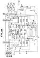
- a culture vessel 11 (Fig. 2B) is in the form of a hollow-fibre filter using a known hollow fibre.
- the filter 11 has a passage 11a for a culture medium, culture chambers 11b and partition walls 11c between them for excluding material of a predetermined molecular weight.
- a first temperature control means 13 for example, a water jacket, maintains the filter at the desired environmental temperature.
- the filter 11 further comprises an inlet 15 for supplying an inoculation culture and an outlet 17 for removing products from the filter 11.
- a product receiving tank 91 is connected through a manually operable value MV1 to the outlet 17.
- a culture medium supply section 21 comprises a culture medium adjusting reservoir 23 for adjusting such parameters as pH and DO, supply and collection reservoir 25a and 25b, culture medium flow passages provided between the culture vessel 11, the culture medium adjusting reservoir 23 and the reservoir 25a and 25b in predetermined relationship (later described in detail).
- the adjusting reservoir 23 includes level gauges LI2, and the reservoirs 25a and 25b include level gauges LI1 and LI3, respectively.
- the switching-over means are of valves AV1, AV2 and AV3 (later described in detail) provided in a predetermined manner in the flow passages in the culture medium supply section 21, and a control section 81 including means for closing and opening these valves.
- the valves are driven by gas pressure from a gas pressure supply section 61 according to instructions from the control section 81, but the driving of the valves is not limited to this feature. For example, they could be magnetically driven.
- the reservoir 25a and the reservoir 23 are connected through flow passage 31, valve AV1 and flow passage 32.
- the reservoir 25b and the reservoir 23 are connected through flow passage 33, valve AV4 and flow passage 34.
- the reservoir 23 and one end of the flow passage 11a of the culture vessel 11 are connected by flow passage 35, which has a flow meter 27, flow passage 36, which has a valve AV7, and flow passage 37, which has a valve AV9. Moreover, the reservoir 23 and the other end of the flow passage 11a are connected by flow passage 35, which has a flow meter 27, flow passage 38, which has a valve AV8, and flow passage 39, which has a valve AV10.
- the flow passages 31 and 36 are connected by valve AV3 and flow passage 41; the flow passages 33 and 36 are connected by valve AV5 and flow passage 42; the flow passages 31 and 38 are connected by valve AV2 and flow passage 43; and the flow passages 33 and 38 are connected by valve AV6 and flow passage 44.
- a culture medium replenishing reservoir 51 is connected through a sterilization filter F5, a valve AV11 and a flow passage 45 to the reservoir 25b and is further connected through a sterilization filter F6, a valve AV12 and a flow passage 46 to the reservoir 25a.
- the culture-medium-adjusting reservoir 23 is supplied through a flow passage 48 with oxygen, carbon dioxide or nitrogen and is further supplied through a flow passage 49 with an alkaline solution (e.g. 7.5% by weight aqueous sodium bicarbonate) through a reservoir 50 as shown in Fig. 2B, thereby adjusting pH or DO in the reservoir 23 by the gas and chemical liquid.
- the reservoir 23 includes a sensor 29a for a pH meter and a sensor 29b for a dissolved oxygen meter as shown in Fig. 2B.
- the introduction of the gas will change the pressure in the reservoir 23, with the result that the surface level of the medium in it is also changed.
- the reservoir 23 comprises a level gauge LI4 and a valve V8 for venting.
- the culture-medium-adjusting reservoir 23 also serves as a buffer for restraining change in flow rate when switching over the flow passages.
- Disused culture medium can be removed from the culture medium adjusting tank 23 through a flow passage 47, a valve AV13 and a sterilization filter F7.
- the culture medium supply section and the culture vessel 11 as above described are accommodated in a constant temperature bath 19 having second temperature control means.
- the gas pressure supply section 61 includes a gas-pressure-producing section 62 having first and second pressure chambers 63a and 63b and a compressor 65 for generating different gas pressures in the chambers 63a and 63b.
- An external gas for example, the air is introduced through a filter F1 and a magnetic three-way valve SV1 into the compressor 65, where the gas is compressed and fed into and stored in the first pressure chamber 63a.
- a remaining passage of the three-way valves SV1 is connected to the second pressure chamber 63b. The pressure in the first pressure chamber is therefore higher than that of the second pressure chamber.
- first and second pressure chambers 63a and 63b are provided with pressure gauges PSI1 and PSI2, both of which have pressure switches, and are connectable by a primary pressure regulating valve RV2. These pressure chambers can be set at predetermined pressures in order to supply gas pressures from these pressure chambers for feeding the culture medium under pressure difference.
- the pressure in the first pressure chamber 63a reaches a predetermined value
- the pressure in the chamber 63a is regulated by primary pressure-regulating valve RV2. If the pressure in the first pressure chamber 63a becomes lower than the predetermined value, the magnetic three-way valve SV1 is switched over to the air-introducing side (filter F1 side) to replenish the air in the pressure chamber 63a until the desired pressure is reached.
- the three-way valve SV1 is also switched over to the air-introducing side to introduce external air into the chamber 63a. Thereafter, an excess of air in the chamber 63a is fed through the primary pressure regulating valve RV2 into the second pressure chamber 63b.
- a gas glow passage 71 having a pressure-regulating valve RV1, a magnetic valve V1, a magnetic three-way valve SV2 and a sterilization filter F2.
- a gas flow passage 72 having a valve V2, a three-way valve SV3 and a filter F3.
- the three-way valve SV2 and the gas flow passage 72 are connected by a gas flow passage 73
- the three-way valve SV3 and the gas flow passage 71 are connected by a gas flow passage 74.
- one of the reservoirs 25a and 25b is connected to the first pressure chamber 63a, while the other is connected to the second pressure chamber 63b, so that a pressure difference occurs between the reservoirs 25a and 25b to enable the culture medium to be fed under pressure difference into either of the tanks.
- the gas for feeding the culture medium under pressure has been said to be air in the above embodiment.
- the amount of dissolved gas in the culture medium greatly affects the proliferation of cells or formation of products, depending upon the substances involved.
- Too much or too little oxygen can be dissolved in the culture medium, i.e. more or less than the equilibrium amount under the atmospheric pressure, and there are culture materials for which the former case is the better environment, and those for which the latter is better. When such substances are cultivated, it is preferable to use the appropriate amount of dissolved oxygen in the culture medium.
- the gas used for feeding the medium under pressure difference is chosen so that for example the equilibrium amount of oxygen dissolved in the medium can be easily controlled by changing the gas or components of it.
- a culture material preferring dissolved oxygen in excess of the equilibrium amount under atmospheric pressure air mixed with oxygen at a high concentration is supplied through filter F1 into the gas pressure producing section shown in Figs. 2A and 2B.
- a culture substance preferring dissolved oxygen in amount is less than the equilibrium amount, air having a low concentration of oxygen, e.g. obtained by dilution with nitrogen, can be supplied.
- the section for controlling the respective components can be constructed according to known control techniques. That shown at 81 in Fig. 2a comprises a microprocessor 83, a memory device 85 for storing data such as feeding directions of culture media and programmes of culture conditions, an input unit 87 for instructing mode selection and change of the feeding directions and culture conditions, input and output (I/O) ports for reading pressure data of the first and second pressure chambers, flow rates of culture media, data of pH, DO and other parameters, data of amounts of culture media in the respective reservoirs, and outputting instruction signals for modifying parameters such as pressure, pH and DO and operating the respective values on the basis of these data, and a display unit 90 for displaying various messages.
- a microprocessor 83 for storing data such as feeding directions of culture media and programmes of culture conditions
- an input unit 87 for instructing mode selection and change of the feeding directions and culture conditions
- input and output (I/O) ports for reading pressure data of the first and second pressure chambers, flow rates of culture media, data of pH, DO and other parameters, data of
- hollow-fibre filter cartridges having a molecular weight cut off of 30,000 and manufactured by Grace Co. under the trade name of "Vitafiber II" are used for the culture vessel.
- the reservoirs 23, 25a and 25b and the flow passages inside the zone bounded by sterilization filters F2, F3, F5, F6, F7, F9, F10 and F11 associated with the culture medium supply section 21 are sterilized by steam at any suitable temperature, for example, 120°C for a predetermined time, for example, 30 minutes.
- the culture medium is supplied from the culture-medium-replenishing reservoir into the culture medium supply section.
- the culture medium is first replenished from the replenishing reservoir 51 into one of the supply and collection reservoirs, for example, 25a. Thereafter, the culture medium is fed through the culture-medium-adjusting reservoir 23 into the other of reservoirs 25a and 25b.
- valve V1 is opened and the gas, pressurized or adjusted by pressure-adjusting valve RV1, is supplied from the first pressure chamber 63a through the flow passage 75 and the sterilization filter F8 into the reservoir 51.
- valve V2 the three-way valve SV3 and valves AV6, AV8 and AV1 are operated respectively to make effective the passage of the second pressure chamber 63b, the gas flow passage 72, the reservoir 25b, the flow passage 33, valve AV6, the flow passages 44 and 38, the valve AV8, the flow passage 35, the flow meter 27, the reservoir 23, the flow passage 32, the valve AV1 and the flow passage 31, thereby forming a pressurized feeding system through the culture-medium-replenishing reservoir 51, the reservoirs 25a and 25b, and the reservoir 23.
- the valve AV12 is opened to supply the culture medium from the supply reservoir 51 through the flow passage 46 into the first reservoir 25a, and the culture medium is fed under pressure difference from the first reservoir 25a through the adjusting reservoir 23 into the second reservoir 25b.
- the amount of the culture medium in the second reservoir 25b is monitored by means of the level gauge LI3.
- the valves AV1, AV6 and AV8 are closed.
- the three-way valve SV3 is switched over to the side of the flow passage 74 to make effective the passage of the second pressure chamber 63b, the valve V2, the three-way valve SV3, the flow passages 74 and 71, the filter F2, the first tank 25a, the flow passage 46 and the valve AV12.
- the liquid surface of the culture medium in the first tank 25a is monitored by the level gauge L1. When it is detected that the liquid surface has arrived at the upper limit level of the gauge LI1, the valves AV12 and AV6 are closed.
- valve V1 and the three-way valve SV2 are actuated to supply the gas pressure in the first pressure chamber 63a, adjusted to a predetermined pressure by the pressure adjusting valve RV1, into the reservoir 25a through the gas flow passage 71.
- the gas pressure adjusted to the predetermined pressure of the pressure adjusting valve RV1 is referred to sometimes as "first gas pressure”.
- valve V2 and the three-way valve SV3 are actuated to supply the gas pressure in the second pressure chamber 63b to the reservoir tank 25b through the gas flow passage 72.
- the gas pressure in the second pressure chamber to be supplied into the second tank 25b is referred to sometimes as "second gas presure”.
- the valves AV1, AV8 and AV6 are opened to feed the culture medium in the reservoir 25a under pressure difference into the reservoir 25b through the culture-medium-adjusting reservoir 23.
- the amount of the culture medium in the reservoir 23 is monitored by means of the level gauge LI2.
- respective parameters such as the pH and DO of the medium are measured by sensors 29a and 29b. These measured results are fed into control section 81 and if the values of these parameters are outside the range of values suitable for culture cells, the culture medium is treated so as to bring the values to the desired levels.
- oxygen can be replenished through the flow passage 48 into the reservoir 23, or if less oxygen is required, nitrogen is added through the passage 48.
- an alkaline solution in the reservoir tank 50 is supplied through the flow passage 49 into the reservoir 23; if a lower pH is needed, CO2 gas is supplied through the flow passages 48 into the reservoir 23 or an acid aqueous solution may be supplied through passage 48.
- the culture medium in the adjusting tank 23 is controlled substantially at a predetermined temperature.
- the temperature of the medium in the culture vessel is controlled with higher accuracy by means of the first temperature control means 13.
- the medium is not immediately supplied to the culture vessel 11 (by keeping the valves AV9 and AV10 closed) and is circulated in the culture medium supply section 21 to stabilize it.
- the medium in the reservoir 23 is first fed under pressure difference into the reservoir 25b through the flow passage 35, the valves AV8 and AV6 and the flow passage 33.
- the upper level of the culture medium in the reservoir 25b is monitored by the level gauge LI3.
- the valve AV6 is then closed and the valve AV4 is opened.
- the three-way valves SV2 and SV3 are opened to switch over the gas flow passages so that the second gas pressure is supplied from the second pressure chamber 63b into the reservoir 25a and the first gas pressure is supplied from the first pressure chamber 63a into the reservoir 25b.
- the valve AV1 is closed, and the valves AV7 and AV3 are opened.
- the culture medium is then fed under pressure difference from the reservoir 25b into the reservoir 23 in which the parameters such as the pH are adjusted in the manner as above described. Then, the adjusted culture medium is fed under pressure difference into the reservoir through the flow passage 35, the valve AV7, the flow passage 36, the valve AV3 and the flow passage 31.
- the culture medium is cyclically circulated between the medium adjusting reservoir 23 and the reservoirs 25a and 25b in the manner as above described to bring the temperature, pH and DO of the culture medium to the desired predetermined values.
- innoculation cells are poured into the culture chamber 11b through the inlet 15 of the hollow fibre 11 under an environment that has been treated so as not to contaminate the inoculation cells.
- the supply of the culture medium to the culture vessel will be explained with reference to the case above, in the supply section, the first gas pressure is supplied into the reservoir 25a and the second gas pressure is supplied into the reservoir 25b, while the culture medium returning from the vessel 11 is stored or collected in the reservoir 25b (as shown in Fig. 2).
- the culture medium in the first reservoir 25a is fed, for a first period under pressure difference, through the reservoir 23 by way of the flow passage 35, the valve AV7, the flow passage 36, the valve AV9, the flow passage 37, the culture vessel 11, the flow passage 39, the valves AV10 and AV6, the flow passage 33 and the reservoir 25b for a period of time during cell culture.
- the culture medium in the first reservoir 25a is fed under pressure difference through the reservoir 23 by way of the flow passage 35, the valve AV8, the flow passage 38, the valve AV10, the flow passage 39, the culture vessel 11, the flow passage 37, the valve AV9, the flow passage 42, the valve AV5, the flow passage 33 and the reservoir 25b.
- the culture medium is caused to flow successively in opposite directions, with the number and frequency of switching over operations being appropriately determined according to the culture cells.
- the direction of the culture medium fed into the culture vessel is changed periodically.
- the culture medium flow passages as above described are switched over so that the second gas is supplied to the reservoir 25a, while the first gas is supplied to the reservoir 25b to collect the culture medium returning from the culture vessel 11 in the reservoir 25a.
- the culture medium supply can be effected in the manner described above.
- the culture medium can be fed under pressure difference in one direction without switching over the flow directions of the culture medium in the culture vessel.
- Sampling is carried out to estimate the yield of product with a view to optimizing it.
- the valve AV9 (or AV10) downstream of the flow of the culture medium in the culture vessel 11 is closed, and the valve MV1 between the outlet 17 of the culture vessel 11 and a product-receiving reservoir 91 is opened.
- a pressure difference occurs between the culture-medium-adjusting reservoir 23 and the product-receiving reservoir 91, so that the produce in the culture chamber 11b is fed together with the culture medium under pressure difference into the product-receiving reservoir 91.
- the cels sampled in this manner are observed with microscopes, other products with suitable reagents.
- the time to change the culture medium is determined. Further, part of the culture medium is sampled by passage through the reservoir 23, the flow passage 47, the valve AV13 and the sterilization filter F7. Metabolites such as glucose and lactic acid in the sampled culture medium are estimated to find the amounts of components consumed and changes in waste material, in addition to the above observations. The results of the estimation may be used for determining the exchange time of the culture medium.
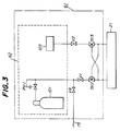
- the gas-pressure-producing section 62 may be constructed in a simple manner, as shown in Fig. 3, where it includes a high-pressure gas bomb 101, with a pressure regulator and a valve V2 on the lower pressure side being directly connected to the atmospheric pressure without providing a low pressure chamber.
- a filter having open mesh at an inlet for introducing the air to protect the sterilization filters F2 and F3.
- the gas pressure may be obtained from such an installation.
- the gas to be introduced into the gas-supply section is not limited to the air.
- Other suitable gases for xample, nitrogen, argon or mixtures of these gases may be used.
- the culture medium supply section has been explained provided with the culture-medium-adjusting reservoir 23.
- the latter is not essential and pH and DO may instead be adjusted in the culture medium supply and collection tank or any appropriate flow passages.
- the culture system of the above embodiment has been shown provided with means for adjusting the pH, DO and temperature of the culture medium, but it may also be provided with means for adjusting other parameters, for example, dissolved concentration of CO2, depending upon the material to be cultivated.
- the supply of the culture medium and the removal of products may be effected by suction with negative pressure.
- the flow passage 75 between the sterilization filter F8 and the valve V6 is removed and once end of the filter F8 on the side oppsotie to the replenishing tank 51 is opened or exposed to the atmosphere.
- the three-way valve SV1 is switched over to the side of the second pressure chamber 63b and the compressor 65 is operated. Then the valve V5 is opened and the valve V1 closed, and the air in the second pressure chamber 63a is forced out of the system through the valve V5 to bring the second pressure chamber 63b into negative pressure. Therefore, the respective valves are switched over so that the system of the second pressure chamber 63b, the valve V2, the three-way valve SV3, the flow passages 74 and 71, the filter F2, the first tank 25a and the flow passage 46 becomes effective. The valve AV12 is then opened so that the culture medium in the replenishing tank 51 is fed under pressure difference into the first reservoir 25a by suction.
- the liquid level of the culture medium in the reservoir 25a is monitored by the level gauge LI1 of the tank.
- the gauge LI1 detects that the medium has reached its upper limit, the valves AV12 and V2 are closed.
- the gas-pressure-producing section is brought into a condition similar to the culture-medium-supplying condition above described. Thereafter, the respective valves are switched over so that the effective flow system consists of the first pressure chamber 63a, the valves RV1, V1 and SV2, the flow passage 71, the filter F2, the reservoir 25a, the flow passage 31, the valve AV1, the flow passage 32, the culture-medium-adjusting reservoir 23, the flow meter 27, the flow passage 35, the valve AV8, the flow passages 38 and 44, the valve AV6, the flow passage 33, the reservoir 25b, the filter F3, the flow passage 72, the valves SV3 and V2 and the second pressure chamber 63b.
- the culture medium in the first tank 25a is supplied through the adjusting tank 23 into the second tank 25b.
- the amount of the culture medium fed into the second tank 25b is monitored by the level gauge LI3.
- the above flow system is completely closed so that the gas-producing section is returned to the suction mode as above described, whereby the culture medium in the culture-medium-replenishing reservoir 51 is replenished into the reservoir 25a in the manner described above.
- the amount of the culture medium in the first tank 25a is monitored by the level gauge LI1.
- the valve AV12 is closed.
- the liquid surfaces of the medium replenished in the reservoirs 25a, 25b and 23 as above described are shown in Fig. 2B.
- the replenishment of the culture medium can be effected by suction in this manner.
- the culture medium supply section and the gas-pressure-producing section are not limited to the above embodiments and various modifications may be made depending upon supplying methods of the culture medium.
- the culture system may be constituted as shown in Fig. 4 to provide for the features that a culture medium is continuously introduced into the culture system from outside, continuously supplied to the culture vessel and continuously drained out of the culture system, that a culture medium is continuously supplied into the culture vessel, while part of the culture medium is circulated in the culture system or drained out of the culture system, and that a culture medium is circulated in the culture system while part of the culture medium is drained out of the culture system or is replenished from outside of the culture system.
- Figs. 4A and 4B are schematic block diagrams of respective parts of principal portions of a culture system capable of supplying and circulating the culture medium in this manner.
- like components are designated by the same reference numerals as those in Figs. 2A and 2B, while components not essential for an understanding of the embodiment, for example, control section 81 and other detailed parts are omitted.
- a gas-pressure-producing section 162 comprises a negative-gauge pressure-producing section 171 in addition to the component designated by 62 in Fig. 2A.
- the negative-gauge-pressure-producing section 171 comprises a vacuum pump 173, a third pressure chamber 63c, a three-way valve SV4, magnetic valves V10 and V11, and a pressure indicator PSI 3 with a pressure switch.
- the vacuum pump 173 is controlled depending upon a set value of the pressure indicator PSI 3 to maintain the gas pressure in the third pressure chamber 63c at a desired negative gauge pressure.
- the third pressure chamber 63c is connected through a gas flow passage 110 having a magnetic valve V12 to the flow passage 72 (already explained) between the valves V2 and the three-way valve SV3.
- the compressor, the vacuum pump and the valves of the gas-pressure-producing section 162 are operated so that pressures P1, P2 and P3 in the first, second and third pressure chambers 63a, 63b and 63c are maintained in the relation P1 > P2 > atmospheric pressure > P3.
- the three-way valves SV2 and SV3 are switched over to provide four conditions: that the gas pressure P1 is supplied to the reservoir 25a and the gas pressure P2 to the reservoir 25b, that P2 is supplied to the reservoir 25a and P1 to the reservoir 25b, that P1 is supplied to the reservoir 25a and P3 to the reservoir 25b, and that P3 is supplied to the reservoir 25a and P1 to the reservoir 25b.
- a modified culture medium supply section 121 is shown in Fig. 4B.
- the culture medium supply section 121 is fundamentally similar to that shown in Fig. 2B with exception that arrangements of the culture medium flow passages and valves are different from those shown in Fig. 2B.
- the culture medium is supplied through a flow passage 111 shown in Fig. 4B into the reservoir 25a or 25b.
- the culture medium in this reservoir is further caused to flow through a passage of the culture-medium-adjusting tank 23, the flow meter 27, a flow passage 112, a flow direction switch-over bypath block 123 (referred to sometimes The hereinafter "switch-over block"), and a flow passage 113.
- the switch-over block 123 is constructed as follows: A loop-shaped flow passage is formed by a flow passage 36 having a valve AV7, a flow passage 38 having a valve AV8, a flow passage 41 having a valve AV3, and a flow passage 44 having a valve AV6.
- the flow passage 112 is connected to a join between the flow passages 36 and 38, and the flow passage 113 is connected to a join between the flow passages 41 and 44.
- a system consisting of a valve AV9, the culture vessel 11 and a valve AV10.
- These valves are switched over so that in this switch-over block, the flow directions of the culture medium can be switched over and the culture medium circulated without supplying new culture medium into the culture vessel 11 in a similar manner to that explained with reference to Fig. 2B.
- These passages are for supplying the culture medium into the culture vessel 11 in the following order (a) the flow passage 112, the valves AV7 and AV9, the culture vessel 11, the valves AV10 and AV6 and the flow passage 113, or (b) the flow passage 112, the valves AV8 and AV10, the culture vessel 11, the valves AV9 and AV3, and the flow passage 113.
- the other passages are bypass passages for bypassing the culture vessel 11 through the flow passage 112, the valves AV7 and AV3, the flow passage 113 or flow passage 112, the valves AV8 and AV6, and the flow passage 113.
- the switch-over block is constructed as follows.
- the first and second flow passages 36 and 41 having the valves AV7 and AV3 are connected in series with each other.
- the third and fourth passages 38 and 44 having the valves AV8 and AV6 are connected in series with each other.
- the first and second flow passages 36 and 41, which are connected in series, and the third and fourth flow passages 38 and 44, which are connected in series, are connected in parallel in the flow passage consisting of the flow passages 112 and 113.
- the fifth flow passage having the valve AV9 is connected between one end of the culture vessel 11 and the join between the first and second flow passages 36 and 41.
- the sixth flow passage having the valve AV10 is connected between the other end of the culture vessel and the connection between the third and second flow passages 38 and 44.
- a culture medium is continuously introduced into the culture system from the outside, continuously fed into the culture vessel 11, and continuously drained from the outlet of the culture system.
- the respective valves are operated so that the gas pressure P1 is supplied to the reservoir 25a and the gas pressure P3 is supplied to the reservoir 25b. Then the passage comprising the valve AV11, the flow passage 111, the valve AV5, and the reservoir 25b is made effective, so that culture medium is fed under suction from the outside of the culture system through a culture medium supply replenishing line on the primary side of the valve AV11 into the reservoir 25b.
- the passage comprising reservoir 25a, the valve AV1, the culture-medium-adjusting tank 23, the flow meter 27, the flow passage 112, the switch-over block 123, the flow passage 113 and the valve AV3 is made effective, so that the culture medium in the reservoir 25a is drained under positive pressure through the above passage out of the culture system.
- the respective valves are opened so that the gas pressure P3 is supplied to the reservoir 25a and the gas pressure P1 is supplied to the reservoir 25b.
- the passage comprising the valve AV11, the flow passage 111, the valve AV2 and the reservoir 25a is made effective, so that the culture medium is fed under suction from the outside of the culture system into the reservoir 25a.
- the passage comprising the reservoir 25b, the valve AV4, the culture-medium-adjusting tank 23, the flow meter 27, the flow passage 112, the switch-over block 123, the flow passage 113 and the valve AV13 is made effective, so that the culture medium in the reservoir 25b is drained under positive pressure through the above passage including the switch-over block out of the culture system.
- the two passages for supplying and draining the culture medium as above described are used by switching them over under the monitoring of the level gauges LI1 - LI3.
- the supply and drain of the culture medium according to Example 1 is carried out in this manner.
- the respective valves are operated so that the gas pressure P1 is supplied to the reservoir 25a and the gas pressure P2 is supplied to the reservoir 25b.
- the passage formed by the reservoir 25a, the valve AV1, the culture- medium- adjusting chamber 23, the flow meter 27, the flow passage 112, the switch-over block 123, the flow passage 113, the valve AV14, the flow passage 111, the valve AV5 and the reservoir 25b is made effective, so that the culture medium in the first reservoir 25a is fed under positive pressure into the reservoir 25b through the above passage including the switch-over block 123.
- the respective valves are operated so that the gas pressure P2 is supplied to the reservoir 25a and the gas pressure P1 is supplied to the reservoir 25b.
- the passage formed by the reservoir 25b, the valve AV4, the culture-medium-adjusting chamber 23, the flow meter 27, the flow passage 112, the switch-over block 123, the flow passage 113, the valve AV14, the flow passage 111, the valve AV2, and the first tank 25a is made effective, so that the culture medium in the reservoir 25b is fed under positive pressure into the reservoir 25a through the above passage including the switch-over block 123.
- the two culture medium supply and drain passages above described are switched over under monitoring by the level gauges LI1 - LI3 to circulate the culture medium and feed it under pressure difference according to Example 2.
- the valve AV13 is opened and closed in accordance with requirements, so that part of the circulating culture medium can be drained out of the culture system without stopping the supply of culture medium into the culture vessel 11.
- the culture medium can be replenished from outside the culture system without stopping the supply of culture medium to the culture vessel.
- gas-pressure-producing sources have been described as compressor and vacuum pump, other means of obtaining gas pressure, such as a factory pipe line or a compressed gas bomb, could be used.
- the culture-medium-supply section and the gas-pressure-supply section could also be variously modified without departing from the invention.
- Various culture cells may be used, such as those anchored to the hollow fibre or suspended in the culture chamber. Further, the supply of the culture medium to the culture vessel can be effected in a manner such that the direction of flow of the culture medium in the culture system is fixed or is periodicaly reversed.
- the culture medium is fed under gas pressure to the culture vessel.
- the culture medium can be supplied into the culture vessel stably and smoothly without any surge or pulse for a long period of time.
- the system according to the invention is easy to maintain and durable in use because there is no mechanically slidable part and no part with which the culture medium is mechanically in contact. As a result, a maintenance can be carried out without permitting impurities to enter the culture medium, even if the gas pressure supply section fails.
- the flowing directions of the culture medium in the culture vessel are reversed, so that the cultivating environment can be made uniform throughout the culture vessel so that the cultivating yield rate is improved.
- the yield ratio can be improved.
- cultivation can be carried out with an efficiency much higher than that of the prior art to produce cells and substances beneficial for human beings such as immunoglobulin and monoclonal antibodies.
Landscapes
- Chemical & Material Sciences (AREA)
- Organic Chemistry (AREA)
- Health & Medical Sciences (AREA)
- Life Sciences & Earth Sciences (AREA)
- Engineering & Computer Science (AREA)
- Bioinformatics & Cheminformatics (AREA)
- Zoology (AREA)
- Wood Science & Technology (AREA)
- Microbiology (AREA)
- Sustainable Development (AREA)
- Biotechnology (AREA)
- Biomedical Technology (AREA)
- Biochemistry (AREA)
- General Engineering & Computer Science (AREA)
- General Health & Medical Sciences (AREA)
- Genetics & Genomics (AREA)
- Analytical Chemistry (AREA)
- Apparatus Associated With Microorganisms And Enzymes (AREA)
Claims (25)
- Procédé de délivrance d'un milieu de culture dans un récipient de culture caractérisé en ce que le récipient de culture est raccordé entre deux réservoirs de délivrance et de collecte de milieu de culture qui contiennent à la fois un milieu de culture et une phase gazeuse, la pression de la phase gazeuse dans l'un des réservoirs étant différente de celle dans l'autre, ce par quoi le milieu de culture s'écoule d'un réservoir vers l'autre, et ce par quoi des changements appropriés de pression gazeuse dans les réservoirs peuvent inverser le sens d'écoulement du milieu de culture.
- Procédé selon la revendication 1, dans lequel les pressions gazeuses sont modifiées par permutation ce qui entraîne la transposition des raccordements des conduits d'écoulement de gaz reliés (a) aux phases gazeuses respectives de deux chambres de pression, dont chacune a une pression gazeuse différente de l'autre, et (b) a des phases gazeuses respectives de deux réservoirs de délivrance et de collecte de milieu de culture.
- Procédé selon la revendication 1 ou 2, dans lequel au moins l'un des composants du gaz est modifié pour commander la quantité dissoute d'équilibre de gaz dans le milieu de culture.
- Procédé selon la revendication 1 ou 2, dans lequel de l'air contenant de l'oxygène en une concentration plus élevée que celle de l'air atmosphérique est utilisé comme gaz.
- Procédé selon la revendication 1 ou 2, dans lequel de l'air contenant de l'oxygène en une concentration plus faible que celle de l'air atmosphérique est utilisé comme gaz.
- Procédé selon l'une quelconque des revendications 1 à 5, dans lequel le milieu de culture est introduit de façon continu dans un système de culture incluant le récipient de culture et des moyens pour produire la différence de pression, est délivré en continu dans le récipient de culture, et est soutiré en continu hors du système de culture.
- Procédé selon l'une quelconque des revendications 1 à 5, dans lequel le milieu de culture est introduit dans un système de culture comportant le récipient de culture et des moyens pour produire la différence de pression et est mis en circulation en continu dans le système de culture.
- Procédé selon les revendications 6 et 7, dans lequel la l'opération pour délivrer en continu le milieu de culture dans le système de culture et pour le soutirer de celui-ci et l'opération pour le faire circuler en continu dans le système de culture sont exécutées de façon alternée.
- Système de culture comprenant au moins un récipient de culture (11), une section de délivrance de milieu de culture (21) et une section de fourniture de pression gazeuse (61) ;
la section de délivrance de milieu de culture (21) ayant au moins deux, c'est-à-dire un premier (25a) et un second (25b), réservoirs de délivrance et de collecte de milieu de culture, où chacun de ces réservoirs (25a, 25b) sert à contenir une phase gazeuse et une phase milieu de culture et est pourvu d'au moins un orifice de gaz et d'au moins un orifice de milieu de culture ;
le récipient de culture (11) comportant deux orifices de milieu de culture, l'orifice de milieu de culture du premier réservoir de délivrance et de collecte de milieu de culture (25a) étant relié à l'un des orifices de milieu de culture du récipient de culture (11) par un conduit d'écoulement de milieu de culture (37 ou 39), et l'autre orifice de milieu de culture du récipient de culture (11) étant relié à l'orifice de milieu de culture du second réservoir de délivrance et de collecte de milieu de culture (25b) par un conduit d'écoulement de milieu de culture (39 ou 37) ; et
la section de fourniture de pression gazeuse (61) comprenant une section de production de pression gazeuse (62) pour produire du gaz à au moins deux pressions différentes et comportant au moins deux orifices de gaz pour délivrer les deux pressions gazeuses différentes, l'un des orifices de gaz de la section de production de pression gazeuse (62) étant relié à l'orifice de gaz du premier réservoir (25a) par un conduit d'écoulement de gaz (71 ou 72), et l'autre orifice de gaz de la section de production de pression gazeuse (62) étant relié à l'orifice de gaz du second réservoir (25b) par un conduit d'écoulement de gaz (72 ou 71). - Système selon la revendication 9, dans lequel la section de délivrance de milieu de culture comprend des premier et second réservoirs de délivrance et de collecte de milieu de culture (25a, 25b), un réservoir d'ajustement de milieu de culture (23) placé entre lesdits premier et second réservoirs, des conduits d'écoulement pour relier ces réservoirs (23, 25a, 25b) et le récipient de culture (11) et des moyens de permutation pour les conduits d'écoulement.
- Système selon la revendication 10, dans lequel le réservoir d'ajustement de milieu de culture (23) et les premier et second réservoirs de délivrance et de collecte de milieu de culture (25a, 25b) sont munis de jauges de niveau (LI2, LI1, LI3) pour détecter la quantité de milieu de culture dans les réservoirs respectifs.
- Système selon la revendication 10, dans lequel le moyen de permutation est constitué de vannes (AV1 à 8) dans les conduits d'écoulement et d'une section de commande (81) comportant des moyens pour fermer et ouvrir les vannes.
- Système selon la revendication 10, comportant un réservoir de recomplètement de niveau de culture (51) raccordé par un conduit d'écoulement comportant une vanne (AV12) audit premier réservoir (25a) et raccordé par un conduit d'écoulement comportant une vanne (AV11) audit second réservoir (25b).
- Système selon la revendication 10, dans lequel le réservoir d'ajustement de milieu de culture (23) est pourvu de moyens distincts (V3, V4, V9) pour délivrer de l'oxygène, du dioxyde de carbone et de l'azote au réservoir d'ajustement de milieu de culture et est également pourvu de moyens (50) pour délivrer une solution alcaline, pour ajuster par ce moyen le pH et la teneur en oxygène dissout du milieu de culture dans le réservoir d'ajustement de milieu de culture (23).
- Système selon la revendication 14, dans lequel le réservoir d'ajustement de milieu de culture (23) est en outre pourvu d'une jauge de niveau (23) et d'une vanne (V8) pour mise à l'air libre.
- Système selon la revendication 9, dans lequel la section de fourniture de pression gazeuse (61) comprend des moyens (SV2, SV3, 71, 72, 73, 74) pour permuter les conduits d'écoulement de gaz vers les orifices de gaz respectifs des deux réservoirs d'alimentation et de collecte de milieu de culture (25a, 25b) de la section de délivrance de milieu de culture (21).
- Système selon la revendication 16, dans lequel la section de production de pression gazeuse (62) comprend des première et seconde chambres de pression (63a, 63b) et un compresseur (65) pour rendre leurs pressions inégales.
- Système selon la revendication 17, dans lequel la section de délivrance de milieu de culture, telle qu'elle est définie dans la revendication 12, et en plus l'un des premier et second réservoirs de délivrance et de collecte de milieu de culture (25a, 25b), sont raccordés à la première chambre de pression (63a) et l'autre à la seconde chambre de pression (63b).
- Système selon la revendication 18, dans lequel les liaisons entre les premier et second réservoirs de délivrance et de collecte de milieu de culture (25a, 25b) et les première et seconde chambres de pression (63a, 63b) peuvent être permutées.
- Système selon la revendication 16, dans lequel la section de production de pression gazeuse (62) comprend des moyens de fourniture de pression et des moyens de régulation de pression pour réguler la pression qui en est issue, et dans lequel un côté inférieur de la section de production de pression gazeuse (62) est directement ouvert à la pression atmosphérique.
- Système selon la revendication 20, dans lequel les moyens d'alimentation en pression sont constitués par une bombonne de gaz à haute pression.
- Système selon la revendication 9, dans lequel la section de fourniture de pression gazeuse (61) comprend une section de production de section gazeuse, une section de production de pression gazeuse négative (171), des conduits d'écoulement de gaz disposés entre la section de production de pression gazeuse et la section de délivrance de milieu de culture et entre la section de production de pression gazeuse et la section de production de pression gazeuse négative (171), et des moyens de permutation pour permuter les conduits d'écoulement.
- Système selon la revendication 22, dans lequel la section de production de pression gazeuse négative (171) comprend une pompe à vide (173), une troisième chambre de pression (63c) pour emmagasiner du gaz sous pression négative, des conduits d'écoulement de gaz entre la pompe à vide (173), la troisième chambre de pression (63c) et d'autres composants dans la section de fourniture de pression gazeuse, et des moyens de permutation pour permuter les conduits d'écoulement.
- Système selon la revendication 9, dans lequel la section de délivrance de milieu de culture comprend des premier et second réservoirs de délivrance et de collecte de milieu de culture (25a, 25b), un réservoir d'ajustement de milieu de culture (23) placé entre ces réservoirs (25a, 25b), une dérivation entre le réservoir d'ajustement de milieu de culture (23) et les premier et second réservoirs de délivrance et de collecte de milieu de culture (25a, 25b), des conduits d'écoulement pour relier ces réservoirs et la dérivation, et des moyens de permutation pour les conduits d'écoulement.
- Système selon la revendication 24, dans lequel la dérivation comprend des premier et deuxième conduits d'écoulement (36, 41) comportant, respectivement, des vannes (AV7, AV3), et raccordées en série l'une avec l'autre, des troisième et quatrième conduits d'écoulement (38, 44) comportant, respectivement, des vannes (AV8, AV6) raccordées en série l'une avec l'autre, les deux paires de conduits (36, 41) et (38, 44) étant elles mêmes raccordées en parallèle dans un conduit d'écoulement (112, 113) des moyens de dérivation, un cinquième conduit d'écoulement comportant une vanne (AV9) et reliant l'une des extrémités du récipient de culture (11) et la jonction entre les premier et deuxième conduits d'écoulement (36, 41), et un sixième conduit d'écoulement comportant une vanne (AV10) et reliant l'autre extrémité du récipient de culture (11) et la jonction entre les troisième et quatrième conduits d'écoulement (38, 44).
Applications Claiming Priority (4)
| Application Number | Priority Date | Filing Date | Title |
|---|---|---|---|
| JP22838086 | 1986-09-29 | ||
| JP228380/86 | 1986-09-29 | ||
| JP20551087A JPH0728715B2 (ja) | 1986-09-29 | 1987-08-19 | 培養液供給方法及び培養装置 |
| JP205510/87 | 1987-08-19 |
Publications (3)
| Publication Number | Publication Date |
|---|---|
| EP0263634A2 EP0263634A2 (fr) | 1988-04-13 |
| EP0263634A3 EP0263634A3 (en) | 1989-02-08 |
| EP0263634B1 true EP0263634B1 (fr) | 1993-08-11 |
Family
ID=26515092
Family Applications (1)
| Application Number | Title | Priority Date | Filing Date |
|---|---|---|---|
| EP19870308623 Expired - Lifetime EP0263634B1 (fr) | 1986-09-29 | 1987-09-29 | Méthode d'alimentation en milieu de culture et système de culture |
Country Status (2)
| Country | Link |
|---|---|
| EP (1) | EP0263634B1 (fr) |
| DE (1) | DE3786978T2 (fr) |
Families Citing this family (7)
| Publication number | Priority date | Publication date | Assignee | Title |
|---|---|---|---|---|
| US5316905A (en) * | 1986-09-29 | 1994-05-31 | Suzuki Shokan Co., Ltd. | Culture medium supplying method and culture system |
| CA2011653A1 (fr) * | 1989-03-08 | 1990-09-08 | Hiroshi Deno | Methode de culture des tissus vegetaux, appareil utilise a cette fin et methode de production de metabolites |
| JP5023795B2 (ja) * | 2007-04-27 | 2012-09-12 | 東洋製罐株式会社 | 細胞培養方法、細胞培養システム、及び培地調整装置 |
| EP2591088B1 (fr) * | 2010-07-05 | 2021-04-21 | BPC Instruments AB | Système de fermentation biologique |
| CN106591121B (zh) * | 2016-11-30 | 2019-04-05 | 广州博敏科技有限公司 | 旋转培养室及旋转脉动培养系统 |
| IL263127B (en) * | 2018-11-19 | 2022-07-01 | The Interdisciplinary Center Herzliya Cc | A liquid-based biological system |
| FR3094012B1 (fr) * | 2019-03-20 | 2022-08-12 | Cherry Biotech Sas | Procédé d'enrichissement en gaz et simultanément de déplacement d’un fluide et dispositif pour le contrôle de l'environnement cellulaire sur une plaque de culture cellulaire multipuits correspondant. |
Family Cites Families (4)
| Publication number | Priority date | Publication date | Assignee | Title |
|---|---|---|---|---|
| US2923669A (en) * | 1954-11-22 | 1960-02-02 | Millipore Filter Corp | Method of bacterial analysis |
| CA1170596A (fr) * | 1981-06-18 | 1984-07-10 | Pierre Marsot | Systeme de culture d'algues a fibres dialysantes |
| JPS59132883A (ja) * | 1982-12-20 | 1984-07-31 | モンサント・コンパニ− | 生物触媒反応装置 |
| WO1987006610A1 (fr) * | 1986-04-28 | 1987-11-05 | Endotronics, Inc. | Procede de culture de leucocytes |
-
1987
- 1987-09-29 DE DE19873786978 patent/DE3786978T2/de not_active Expired - Fee Related
- 1987-09-29 EP EP19870308623 patent/EP0263634B1/fr not_active Expired - Lifetime
Also Published As
| Publication number | Publication date |
|---|---|
| DE3786978D1 (de) | 1993-09-16 |
| EP0263634A2 (fr) | 1988-04-13 |
| EP0263634A3 (en) | 1989-02-08 |
| DE3786978T2 (de) | 1994-03-03 |
Similar Documents
| Publication | Publication Date | Title |
|---|---|---|
| US5316905A (en) | Culture medium supplying method and culture system | |
| US6576458B1 (en) | Cell and tissue culture device with controlled culture fluid flow | |
| US9670451B2 (en) | Methods and systems of growing and harvesting cells in a hollow fiber bioreactor system with control conditions | |
| US5424209A (en) | Automated cell culture and testing system | |
| CA1270455A (fr) | Appareil et methode pour la culture des cellules, l'elimination des dechets et la concentration du produit | |
| EP2566951B1 (fr) | Procédé de réensemencement de cellules adhérentes cultivées dans un système de bioréacteur à fibres creuses | |
| EP0260627B1 (fr) | Incubateur sous pression | |
| WO1986002379A1 (fr) | Dispositif de culture a fibres creuses pour ameliorer la perfusion de substances nutritives et la concentration des produits, et procede de fonctionnement | |
| EP0263634B1 (fr) | Méthode d'alimentation en milieu de culture et système de culture | |
| JPH10512159A (ja) | 生物人工肝臓のための培養製品 | |
| US5286646A (en) | Method for mammalian cell culture | |
| CA2876523C (fr) | Procede et systeme de culture cellulaire | |
| US11667882B2 (en) | Device and method for controlling a bioreactor | |
| JPH03992B2 (fr) | ||
| AU778141B2 (en) | Method for cultivating cells, a membrane module, utilization of a membrane module and reaction system for cultivation of said cells | |
| JPS62130683A (ja) | 哺乳動物細胞を培養する方法および装置 | |
| JP3412364B2 (ja) | 細胞培養装置及び細胞培養方法 | |
| JPH0728715B2 (ja) | 培養液供給方法及び培養装置 | |
| JPH01291783A (ja) | 閉鎖系藻類培養装置 | |
| WO1990002170A1 (fr) | Bioreacteur a membrane | |
| RU2626526C1 (ru) | Система создания биоинженерных моделей тканей животных и человека | |
| JP6847431B2 (ja) | 成育装置 | |
| JPH0538281A (ja) | 細胞培養装置 | |
| RU2021353C1 (ru) | Способ культивирования микроорганизмов и установка для его осуществления | |
| RU2031933C1 (ru) | Установка для каскадно-проточного культивирования микроорганизмов |
Legal Events
| Date | Code | Title | Description |
|---|---|---|---|
| PUAI | Public reference made under article 153(3) epc to a published international application that has entered the european phase |
Free format text: ORIGINAL CODE: 0009012 |
|
| AK | Designated contracting states |
Kind code of ref document: A2 Designated state(s): CH DE FR GB LI NL SE |
|
| PUAL | Search report despatched |
Free format text: ORIGINAL CODE: 0009013 |
|
| AK | Designated contracting states |
Kind code of ref document: A3 Designated state(s): CH DE FR GB LI NL SE |
|
| 17P | Request for examination filed |
Effective date: 19890621 |
|
| 17Q | First examination report despatched |
Effective date: 19920302 |
|
| GRAA | (expected) grant |
Free format text: ORIGINAL CODE: 0009210 |
|
| AK | Designated contracting states |
Kind code of ref document: B1 Designated state(s): CH DE FR GB LI NL SE |
|
| PG25 | Lapsed in a contracting state [announced via postgrant information from national office to epo] |
Ref country code: SE Effective date: 19930811 Ref country code: NL Effective date: 19930811 |
|
| REF | Corresponds to: |
Ref document number: 3786978 Country of ref document: DE Date of ref document: 19930916 |
|
| ET | Fr: translation filed | ||
| NLV1 | Nl: lapsed or annulled due to failure to fulfill the requirements of art. 29p and 29m of the patents act | ||
| PLBE | No opposition filed within time limit |
Free format text: ORIGINAL CODE: 0009261 |
|
| STAA | Information on the status of an ep patent application or granted ep patent |
Free format text: STATUS: NO OPPOSITION FILED WITHIN TIME LIMIT |
|
| 26N | No opposition filed | ||
| PGFP | Annual fee paid to national office [announced via postgrant information from national office to epo] |
Ref country code: GB Payment date: 19960927 Year of fee payment: 10 Ref country code: FR Payment date: 19960927 Year of fee payment: 10 |
|
| PGFP | Annual fee paid to national office [announced via postgrant information from national office to epo] |
Ref country code: CH Payment date: 19960930 Year of fee payment: 10 |
|
| PGFP | Annual fee paid to national office [announced via postgrant information from national office to epo] |
Ref country code: DE Payment date: 19961023 Year of fee payment: 10 |
|
| PG25 | Lapsed in a contracting state [announced via postgrant information from national office to epo] |
Ref country code: GB Free format text: LAPSE BECAUSE OF NON-PAYMENT OF DUE FEES Effective date: 19970929 |
|
| PG25 | Lapsed in a contracting state [announced via postgrant information from national office to epo] |
Ref country code: LI Free format text: LAPSE BECAUSE OF NON-PAYMENT OF DUE FEES Effective date: 19970930 Ref country code: FR Free format text: THE PATENT HAS BEEN ANNULLED BY A DECISION OF A NATIONAL AUTHORITY Effective date: 19970930 Ref country code: CH Free format text: LAPSE BECAUSE OF NON-PAYMENT OF DUE FEES Effective date: 19970930 |
|
| REG | Reference to a national code |
Ref country code: CH Ref legal event code: PL |
|
| GBPC | Gb: european patent ceased through non-payment of renewal fee |
Effective date: 19970926 |
|
| PG25 | Lapsed in a contracting state [announced via postgrant information from national office to epo] |
Ref country code: DE Free format text: LAPSE BECAUSE OF NON-PAYMENT OF DUE FEES Effective date: 19980603 |
|
| REG | Reference to a national code |
Ref country code: FR Ref legal event code: ST |