EP0263455A2 - Fuel supply device for carburetors - Google Patents
Fuel supply device for carburetors Download PDFInfo
- Publication number
- EP0263455A2 EP0263455A2 EP87114470A EP87114470A EP0263455A2 EP 0263455 A2 EP0263455 A2 EP 0263455A2 EP 87114470 A EP87114470 A EP 87114470A EP 87114470 A EP87114470 A EP 87114470A EP 0263455 A2 EP0263455 A2 EP 0263455A2
- Authority
- EP
- European Patent Office
- Prior art keywords
- fuel
- passageway
- level
- level sensor
- flow rate
- Prior art date
- Legal status (The legal status is an assumption and is not a legal conclusion. Google has not performed a legal analysis and makes no representation as to the accuracy of the status listed.)
- Withdrawn
Links
Images

Classifications
-
- F—MECHANICAL ENGINEERING; LIGHTING; HEATING; WEAPONS; BLASTING
- F02—COMBUSTION ENGINES; HOT-GAS OR COMBUSTION-PRODUCT ENGINE PLANTS
- F02M—SUPPLYING COMBUSTION ENGINES IN GENERAL WITH COMBUSTIBLE MIXTURES OR CONSTITUENTS THEREOF
- F02M7/00—Carburettors with means for influencing, e.g. enriching or keeping constant, fuel/air ratio of charge under varying conditions
- F02M7/12—Other installations, with moving parts, for influencing fuel/air ratio, e.g. having valves
-
- F—MECHANICAL ENGINEERING; LIGHTING; HEATING; WEAPONS; BLASTING
- F02—COMBUSTION ENGINES; HOT-GAS OR COMBUSTION-PRODUCT ENGINE PLANTS
- F02M—SUPPLYING COMBUSTION ENGINES IN GENERAL WITH COMBUSTIBLE MIXTURES OR CONSTITUENTS THEREOF
- F02M17/00—Carburettors having pertinent characteristics not provided for in, or of interest apart from, the apparatus of preceding main groups F02M1/00 - F02M15/00
- F02M17/02—Floatless carburettors
-
- F—MECHANICAL ENGINEERING; LIGHTING; HEATING; WEAPONS; BLASTING
- F02—COMBUSTION ENGINES; HOT-GAS OR COMBUSTION-PRODUCT ENGINE PLANTS
- F02M—SUPPLYING COMBUSTION ENGINES IN GENERAL WITH COMBUSTIBLE MIXTURES OR CONSTITUENTS THEREOF
- F02M3/00—Idling devices for carburettors
- F02M3/08—Other details of idling devices
Definitions
- the present invention relates to a fuel supply device for carburetors provided with a fuel chamber disposed in the middle of a fuel passageway and constructed so that a reference liquid level of fuel is maintained by a first fuel liquid level sensor; and second and third fuel liquid level sensors disposed in a pair of vacuum passageways communicating with the fuel passageway and adapted to control the flow rate of fuel to be supplied to a slow system and a main system of the carburetor, respectively, so that a proper amount of fuel can be supplied with respect to the flow rate of air in the slow and main systems.
- a carburetor designed so that, in addition to the detection of the fuel liquid level mentioned above, a fuel chamber is provided in the middle of the fuel passageway on a fuel supply source side, a solenoid valve is disposed for controlling the flow of fuel to be supplied to the fuel chamber so that the fuel liquid level in the fuel chamber is constantly maintained, and thus the height of the fuel liquid level in the fuel chamber is set as a reference level, thereby holding fuel pressure to the fuel passageway to replace a conventional float chamber. Then, another fuel liquid level sensor is disposed for the detection of the reference fuel liquid level and, in the case of the carburetor with the slow and main systems, such second and third fuel liquid level sensors as mentioned above are further added to each system.
- a plurality of fuel liquid level sensors are to be used and, among them, the level sensor used in particular to maintain the height of the fuel liquid surface in the fuel chamber at the reference level is located on the fuel supply source side and is of high importance. Further, the relationships between this level sensor and the slow and main system level sensors are essential factors in view of the operation of the entire carburetors.
- a primary object of the present invention is to provide a fuel supply device for carburetors in which, even if a fuel liquid level in a fuel chamber fluctuates, its adverse effect is arrested as far as possible and a mixture with a proper air-fuel ratio can always be supplied.
- Another object of the present invention is to provide a fuel supply device for floating-gate carburetors, with a high degree of performance, equipped with a slow system and a main system.
- these objects are accomplished by arranging, separate from the fuel chamber, a first level sensor for maintaining the fuel liquid surface in the fuel chamber at the reference level and arranging, in the vicinity of the first level sensor, second and third level sensors for maintaining the fuel liquid surface in the slow and main systems at predetermined levels.
- the first level sensor can perform normal operation and mutual relations between individual sensors, which are disposed close to each other, are properly held, with the result that accurate operation for the fuel supply device is secured and the supply of the mixture with an always proper air-fuel ratio can be materialized.
- a suction bore a suction bore
- 2 a stationary venturi
- 3 an air valve provided for opening and closing the suction bore
- 4 represents an actuating means for controlling the opening and closing of the air valve 3 provided with a diaphragm 4a
- 5 represents a throttle valve
- 6 represents a venturi in the slow system for bypassing the air valve 3 between its upstream side and downstream side located at the downstream side of the stationary venturi
- 7 represents a fuel chamber substantially configurated in an annular form as shown, for example, in Fig.
- 8 represents a solenoid valve controlling the fuel inlet flow from the not-shown tank into the fuel chamber 7 so as to maintain the liquid surface in the fuel chamber 7 at a predetermined level
- 9 represents a negative pressure passageway opened at one end to the stationary venturi 2, communicating at the other end with the fuel chamber 7 and having an upright part made, for example, of a transparent tube which is arranged in such a way that a fuel column 9 within the upright part is formed so as to be separate from the fuel chamber 7
- 10 represents a first level sensor for the detection of the reference fuel level arranged in the position of a predetermined height of the upright part of the negative pressure passageway 9 and made of a combination, for example, of a light emitting element 10a and a light receiving element 10b so that, in response to whether the level of the fuel column 9a is higher or lower than the predetermined height positon, the output may be large or small
- 11 represents a main jet
- 12 represents a fuel
- 15 represents a solenoid valve controlling the flow rate of the fuel from the main jet 11 so as to maintain the liquid surface of the fuel column 14a at the position of a predetermined height even if a negative pressure within the negative pressure passageway 14 is changed
- 16 represents a second level sensor for the detection of the fuel level in the main system arranged in the position of a predetermined height of the upright part of the negative pressure passageway 14 and made of a combination, for example, of a light emitting element 16a and a light receiving element 16b so that, in response to whether the level of the fuel column 14a is higher or lower than the predetermined height position, the output may be large or small
- 17 represents a negative pressure passageway opened at one end to the venturi 6 in the slow system, communicating at the other end with the fuel passageway 12 ⁇ at the downstream side of a pilot jet 18 and having an upright part made, for example, of a transparent tube which is arranged in such a way that a fuel column 17a within the upright part is located actually in the vicinity of the fuel column 9a
- 19 represents a solenoid valve controlling the flow rate of the fuel from the pilot jet 18 so as to maintain the liquid surface of the fuel column 17a at the position of a predetermined height even if a negative pressure within the negative pressure passageway 17 is changed and 20 represents a third level sensor for the detection of the fuel level in the slow system arranged in the position of a predetermined height of the upright part of the negative pressure passageway 17 and made, for example, of a light emitting element 20a and a light receiving element 20b so that, in response to whether the level of the fuel column 17a is higher or lower than the predetermined height position, the output may be large or small.
- each of the first, second and third sensors is of a photoelectrical type, any of such known types as a float type and a magnetic type or a combination of these types can be used.
- Fig. 3 is a block diagram showing an example of an actuating control circuit of the above-mentioned solenoid valve 8.
- the reference numeral 21 represents a level sensor output circuit connected to the light receiving element 10b
- 22 represents a reference value generating circuit generating a reference value required for presetting the reference value of the fuel liquid surface within the fuel chamber 7
- 23 represents a comparator
- 24 represents a driving circuit for the solenoid valve 8.
- the comparator 23 is constituted in such a way that when the output from the level sensor output circuit 21 is smaller than the output from the reference value generating circuit 22, a signal for operating the solenoid valve 8 is outputted to the driving circuit 24 and on the other hand when the output from the level sensor output circuit 21 is larger than the output from the reference value generating circuit 22, a signal for closing the solenoid valve 8 is outputted to the driving circuit 24.
- actuating control circuits for the solenoid valves 15, 19 are basically in the same way as the above-mentioned control circuit, they are different from the above-mentioned control circuit in the point that they are constituted in such a way that the comparator 23 outputs a pulse with a width proportional to the difference between the output from the level sensor output circuit 21 and the output from the reference value generating circuit 22 and at the same time the driving circuit 24 duty-controls the solenoid valves 15, 19 in response to the pulse width of the output from the comparator 23.
- the actuating control circuits of the solenoid valves 15, 19 may be constituted as an open and close control type or the actuating control circuit of the solenoid valve 8 may be constituted as a duty control type.
- the control circuit of the solenoid valve 15 is provided with a switch-over controller composed of a discriminator which discriminates whether a revolution number detector 25 of the engine, a throttle sensor 26 for detecting the opening of the throttle valve 5 and the driving condition of the engine are within a main region or not, so that when the driving condition of the engine is shifted to the main region the solenoid valve 15 is only then actuated by the control circuit of the main system.
- the solenoid valve 8 When driving the operation of the engine the height of the fuel column 9a is lower than a predetermined height, i.e. the fuel liquid surface within the fuel chamber 7 is lower than the reference level, the solenoid valve 8 is opened because the output from the level sensor output circuit 21 is smaller than the reference value output, resulting in that the liquid surface is raised and on the contrary when the fuel liquid surface is higher than the reference level, the solenoid valve 8 is closed, resulting in that the liquid surface is lowered. In this way the fuel liquid surface within the fuel chamber 7 is maintained at the reference level.
- the solenoid valve 15 is separated from its control circuit by the discrimination of the discriminator 27 that the driving condition of the engine is not within a main region according to the output signals from the revolution number detector 25 of the engine and the throttle sensor 26, resulting in that the solenoid valve 15 is kept in an unactuated state and the fuel passageway is maintained in a closed state.
- the solenoid valve 19 controls the flow rate of the fuel flowing through the fuel passageway 12 ⁇ by the control circuit as shown in Fig. 5 depending on the output signal from the elvel sensor 20 of the slow system so that the fuel column 17a is maintained at a predetermined level, i.e. the negative pressure at the venturi 6 of the slow system and the negative pressure at the downstream side of the pilot jet 18 will be equal.
- the output from the level sensor output circuit 21 controls the solenoid valve 15 by the driving circuit 24 so as to lower the duty ratio because the output from the level sensor output circuit 21 is smaller than the reference value output, resulted in that the flow rate of the fuel through the fuel passageway 12 ⁇ is lowered so as to raise the level of the fuel column 17a up to the predetermined level.
- the control circuit controls the solenoid valve 15 so as to make the flow rate of the fuel larger and thereby to make the duty ratio higher.
- a proper amount of fuel is delivered with respect to the flow rate of the air flowing into the downstream of the throttle valve 5 through the venturi 6 of the slow system and a mixture of a proper fuel-oil ratio with respect to the driving condition of the slow region is supplied to the engine.
- the air valve 3 is gradually opened by the actuation of the acutating means 4 due to the growth of the negative pressure at the upstream side of the throttle valve 5, resulted in that the suction air flowing through the stationary venturi 2 flows mainly within the suction bore 1 by the gradual opening of a port 12a.
- the solenoid valve 15 is connected to the control circuit and shifted to the operation state by the discrimination of the discriminator 27 that the driving condition of the engine is shifted into the main region according to the output signals from the revolution number detector 25 of the engine and the throttle sensor 26. Therefore, the control circuit as shown in Fig.
- the solenoid valve 15 is actuated in a similar way to the control circuit as shown in Fig. 5 and the solenoid valve 15 is duty-controlled so as to maintain the level of the fuel column 14a at a predetermined level. That is to say, the solenoid valve 15 is actuated to control the flow rate of the fuel flowing through the fuel passageway 12 depending on the output signal from the level sensor 16 of the main system so that the negative pressure generated at the stationary venturi 2 and the negative pressure at the downstream of the main jet 11 will be equal, thereby a proper amount of fuel is delivered with respect to the flow rate of the air flowing at the stationary venturi 2 from the port 12a, 12b, the slow port 13 and through the negative passageway 17 simultaneously.
- a mixture of a proper fair-fuel ratio is always supplied with respect to the driving condition in the slow speed region and the high speed region of the engine.
- the fuel liquid level in the fuel chamber 7 fluctuates violently or is inclinated extremely to the horizen when a car turns or runs on a bad road.
- the upright part of the negative pressure passageway i.e. the fuel column 9a
- the fuel column 9a will fluctuate irregularly and violently due to the direct influence from the fluctuation of the fuel liquid level in the fuel chamber 7.
- the fuel column 9a is formed to be separated from the fuel chamber 7 so that the level of the fuel column 9a represents the original fuel liquid level in the fuel chamber 7 without a direct transmission of the fuel liquid level fluctuation of the fuel chamber 7 to the fuel column 9a.
- the reference fuel liquid level sensor 10 performs a normal operation so as to set a reference liquid surface within the chamber 7 irrespective of the fluctuation of the fuel liquid surface within the fuel chamber 7 and can supply the fuel with a desired fuel pressure through the main jet 11 into the fuel passageway 12.
- the fuel liquid level sensors 16, 20 of the slow system and of the main system respectively and the solenoid valves 15, 19 also can perform a proper operation.
- the both level sensors 16, 20 of the slow system and of the main system is arranged in the vicinity of the reference fuel liquid level sorsor 10 through 14, 17 and further each fuel column 9a, 14a, 17a is arranged so as to be uniformly affected by the turning or the inclination etc.
- each fuel column and each level sensor are arranged concentratedly in a portion, the fuel chamber 7 can be arranged without the limitation due to the layout of each level sensor 10, 16, 20, therefore a great deal of freedom in the layout design of each member can be obtained advantageously.
- Figs. 6 and 7 show layout examples of the fuel chamber 7 and each fuel column 9a, 14a, 17a according to the second and third embodiments respectively, wherein each fuel column 9a, 14a, 17a is arranged concentratedly in a portion separate from the fuel chamber 7. In this case a similar effect to the first embodiment can be obtained.
Landscapes
- Engineering & Computer Science (AREA)
- Chemical & Material Sciences (AREA)
- Combustion & Propulsion (AREA)
- Mechanical Engineering (AREA)
- General Engineering & Computer Science (AREA)
- Control Of The Air-Fuel Ratio Of Carburetors (AREA)
- Feeding And Controlling Fuel (AREA)
Abstract
Description
- The present invention relates to a fuel supply device for carburetors provided with a fuel chamber disposed in the middle of a fuel passageway and constructed so that a reference liquid level of fuel is maintained by a first fuel liquid level sensor; and second and third fuel liquid level sensors disposed in a pair of vacuum passageways communicating with the fuel passageway and adapted to control the flow rate of fuel to be supplied to a slow system and a main system of the carburetor, respectively, so that a proper amount of fuel can be supplied with respect to the flow rate of air in the slow and main systems.
- An example of conventional carburetors such that the flow rate of fuel to be supplied is controlled by the detection of the position of a fuel liquid level is described in, for example, European Patent Publication No. 0207796 proposed by the same applicant as in this application. Such a carburetor is designed so that, in accordance with a signal issued from a fuel liquid level sensor disposed in the middle of a vacuum passageway opening into the downstream side of a variable venturi at one end and opening into a fuel passageway at another end, the flow rate of fuel flowing through the fuel passageway connected to a fuel supply source is controlled by a solenoid valve so that a fuel liquid level is maintained in a constant position of height, and thereby a mixture has an always constant air-fuel ratio. On the other hand, there is a carburetor designed so that, in addition to the detection of the fuel liquid level mentioned above, a fuel chamber is provided in the middle of the fuel passageway on a fuel supply source side, a solenoid valve is disposed for controlling the flow of fuel to be supplied to the fuel chamber so that the fuel liquid level in the fuel chamber is constantly maintained, and thus the height of the fuel liquid level in the fuel chamber is set as a reference level, thereby holding fuel pressure to the fuel passageway to replace a conventional float chamber. Then, another fuel liquid level sensor is disposed for the detection of the reference fuel liquid level and, in the case of the carburetor with the slow and main systems, such second and third fuel liquid level sensors as mentioned above are further added to each system. That is to say, in such an instance, a plurality of fuel liquid level sensors are to be used and, among them, the level sensor used in particular to maintain the height of the fuel liquid surface in the fuel chamber at the reference level is located on the fuel supply source side and is of high importance. Further, the relationships between this level sensor and the slow and main system level sensors are essential factors in view of the operation of the entire carburetors.
- Now, although it is necessary for such carburetors as stated above to be able to supply always a proper mixture with respect to any driving condiiton of a car in practical use, the fuel liquid level in the fuel chamber sharply fluctuates in, for example, the turn of a car in particular and this adversely affects the actuation of the level sensor for maintaining the reference fuel liquid level. In such a case, problems arise that a normal function of the level sensor is disturbed, and consequently the supply of a proper mixture cannot be performed.
- In view of such circumstances, a primary object of the present invention is to provide a fuel supply device for carburetors in which, even if a fuel liquid level in a fuel chamber fluctuates, its adverse effect is arrested as far as possible and a mixture with a proper air-fuel ratio can always be supplied.
- Another object of the present invention is to provide a fuel supply device for floating-gate carburetors, with a high degree of performance, equipped with a slow system and a main system.
- According to the present invention, these objects are accomplished by arranging, separate from the fuel chamber, a first level sensor for maintaining the fuel liquid surface in the fuel chamber at the reference level and arranging, in the vicinity of the first level sensor, second and third level sensors for maintaining the fuel liquid surface in the slow and main systems at predetermined levels. Thereby, the first level sensor can perform normal operation and mutual relations between individual sensors, which are disposed close to each other, are properly held, with the result that accurate operation for the fuel supply device is secured and the supply of the mixture with an always proper air-fuel ratio can be materialized.
- These and other objects as well as the features and the advantages of the present invention will be apparent from the following detailed description of the preferred embodiment when taken in conjunction with the accompanying drawings.
- In the drawings:
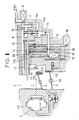
- Fig. 1 is an explanatory longitudinal sectional view of the main part of a carburetor provided with the first embodiment of a fuel supply device according to the present invention;
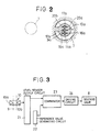
- Fig. 2 is a partly transverse sectional view showing an example of an arrangement of a fuel chamber, each fuel column and each fuel liquid level sensor in the above-mentioned embodiment;
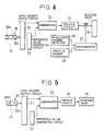
- Fig. 3 is a block diagram showing an example of a control circuit used for maintaining the height of the fuel liquid surface of the fuel chamber at a reference level;
- Fig. 4 is a block diagram showing an example of a control circuit used for maintaining the fuel liquid surface in a main system at a predetermined level;
- Fig. 5 is a block diagram showing an example of a control circuit used for maintaining the fuel liquid surface in a slow system at a predetermined level; and
- Figs. 6 and 7 are partly transverse sectional views showing another arrangement different each other of a fuel chamber, each fuel column and each fuel liquid level sensor.
- Referring to Fig. 1 to Fig. 5 the first embodiment of a fuel supply device according to the present invention will be explained in the following. In figures the
reference numeral 1 represents a suction bore, 2 represents a stationary venturi, 3 represents an air valve provided for opening and closing thesuction bore air valve 3 provided with adiaphragm air valve 3 between its upstream side and downstream side located at the downstream side of thestationary venturi fuel chamber 7 so as to maintain the liquid surface in thefuel chamber 7 at a predetermined level, 9 represents a negative pressure passageway opened at one end to thestationary venturi 2, communicating at the other end with thefuel chamber 7 and having an upright part made, for example, of a transparent tube which is arranged in such a way that afuel column 9 within the upright part is formed so as to be separate from thefuel chamber negative pressure passageway 9 and made of a combination, for example, of alight emitting element 10a and alight receiving element 10b so that, in response to whether the level of thefuel column 9a is higher or lower than the predetermined height positon, the output may be large or small, 11 represents a main jet, 12 represents a fuelpassageway having ports suction bore 1 and to the venturi 6 in the slow system respectively and communicating with aslow port stationary venturi 2, communicating at the other end with thefuel passageway 12 at the downstream of themain jet 11 and having an upright part made, for example, of a transparent tube in such a way that afuel column 14a within the upright part is located actually in the vicinity of thefuel column 9a as shown in Fig. 2, 15 represents a solenoid valve controlling the flow rate of the fuel from themain jet 11 so as to maintain the liquid surface of thefuel column 14a at the position of a predetermined height even if a negative pressure within thenegative pressure passageway 14 is changed, 16 represents a second level sensor for the detection of the fuel level in the main system arranged in the position of a predetermined height of the upright part of thenegative pressure passageway 14 and made of a combination, for example, of alight emitting element 16a and alight receiving element 16b so that, in response to whether the level of thefuel column 14a is higher or lower than the predetermined height position, the output may be large or small, 17 represents a negative pressure passageway opened at one end to the venturi 6 in the slow system, communicating at the other end with the fuel passageway 12ʹ at the downstream side of apilot jet 18 and having an upright part made, for example, of a transparent tube which is arranged in such a way that afuel column 17a within the upright part is located actually in the vicinity of thefuel column 9a as shown in Fig. 2, 19 represents a solenoid valve controlling the flow rate of the fuel from thepilot jet 18 so as to maintain the liquid surface of thefuel column 17a at the position of a predetermined height even if a negative pressure within thenegative pressure passageway 17 is changed and 20 represents a third level sensor for the detection of the fuel level in the slow system arranged in the position of a predetermined height of the upright part of thenegative pressure passageway 17 and made, for example, of alight emitting element 20a and alight receiving element 20b so that, in response to whether the level of thefuel column 17a is higher or lower than the predetermined height position, the output may be large or small. Although each of the first, second and third sensors is of a photoelectrical type, any of such known types as a float type and a magnetic type or a combination of these types can be used. - Fig. 3 is a block diagram showing an example of an actuating control circuit of the above-mentioned
solenoid valve 8. Thereference numeral 21 represents a level sensor output circuit connected to thelight receiving element fuel chamber solenoid valve 8. Thecomparator 23 is constituted in such a way that when the output from the levelsensor output circuit 21 is smaller than the output from the referencevalue generating circuit 22, a signal for operating thesolenoid valve 8 is outputted to thedriving circuit 24 and on the other hand when the output from the levelsensor output circuit 21 is larger than the output from the referencevalue generating circuit 22, a signal for closing thesolenoid valve 8 is outputted to thedriving circuit 24. Although actuating control circuits for thesolenoid valves comparator 23 outputs a pulse with a width proportional to the difference between the output from the levelsensor output circuit 21 and the output from the referencevalue generating circuit 22 and at the same time thedriving circuit 24 duty-controls thesolenoid valves comparator 23. As it is obvious from these explanations, the actuating control circuits of thesolenoid valves solenoid valve 8 may be constituted as a duty control type. Furthermore, as obvious from Fig. 4 the control circuit of thesolenoid valve 15 is provided with a switch-over controller composed of a discriminator which discriminates whether arevolution number detector 25 of the engine, athrottle sensor 26 for detecting the opening of thethrottle valve 5 and the driving condition of the engine are within a main region or not, so that when the driving condition of the engine is shifted to the main region thesolenoid valve 15 is only then actuated by the control circuit of the main system. - Now, the operation of the above-mentioned device will be explained.
- When driving the operation of the engine the height of the
fuel column 9a is lower than a predetermined height, i.e. the fuel liquid surface within thefuel chamber 7 is lower than the reference level, thesolenoid valve 8 is opened because the output from the levelsensor output circuit 21 is smaller than the reference value output, resulting in that the liquid surface is raised and on the contrary when the fuel liquid surface is higher than the reference level, thesolenoid valve 8 is closed, resulting in that the liquid surface is lowered. In this way the fuel liquid surface within thefuel chamber 7 is maintained at the reference level. - When the driving condition of the engine is within a slow region at first, the suction negative pressure at the upstream side of the
throttle valve 5 is extraodinarily low because of the small opening of thethrottle valve 5. Therefore, theair valve 3 is maintained in the condition of closing thesuction bore 1 and consequently a suction air is introduced into a manifold through the venturi 6 of the slow system. On the other hand thesolenoid valve 15 is separated from its control circuit by the discrimination of thediscriminator 27 that the driving condition of the engine is not within a main region according to the output signals from therevolution number detector 25 of the engine and thethrottle sensor 26, resulting in that thesolenoid valve 15 is kept in an unactuated state and the fuel passageway is maintained in a closed state. On the contrary thesolenoid valve 19 controls the flow rate of the fuel flowing through the fuel passageway 12ʹ by the control circuit as shown in Fig. 5 depending on the output signal from theelvel sensor 20 of the slow system so that thefuel column 17a is maintained at a predetermined level, i.e. the negative pressure at the venturi 6 of the slow system and the negative pressure at the downstream side of thepilot jet 18 will be equal. That is to say, when the level of thefuel column 17a is lower than the predetermined level, the output from the levelsensor output circuit 21 controls thesolenoid valve 15 by thedriving circuit 24 so as to lower the duty ratio because the output from the levelsensor output circuit 21 is smaller than the reference value output, resulted in that the flow rate of the fuel through the fuel passageway 12ʹ is lowered so as to raise the level of thefuel column 17a up to the predetermined level. On the other hand, when the level of thefuel column 17a is higher than the predetermined level, the control circuit controls thesolenoid valve 15 so as to make the flow rate of the fuel larger and thereby to make the duty ratio higher. Thus, from aport 12b and a slow port 13 a proper amount of fuel is delivered with respect to the flow rate of the air flowing into the downstream of thethrottle valve 5 through the venturi 6 of the slow system and a mixture of a proper fuel-oil ratio with respect to the driving condition of the slow region is supplied to the engine. - The, when the driving condition of the engine is shifted from the slow region to a high speed region, the
air valve 3 is gradually opened by the actuation of theacutating means 4 due to the growth of the negative pressure at the upstream side of thethrottle valve 5, resulted in that the suction air flowing through thestationary venturi 2 flows mainly within thesuction bore 1 by the gradual opening of aport 12a. On the other hand, thesolenoid valve 15 is connected to the control circuit and shifted to the operation state by the discrimination of thediscriminator 27 that the driving condition of the engine is shifted into the main region according to the output signals from therevolution number detector 25 of the engine and thethrottle sensor 26. Therefore, the control circuit as shown in Fig. 4 is actuated in a similar way to the control circuit as shown in Fig. 5 and thesolenoid valve 15 is duty-controlled so as to maintain the level of thefuel column 14a at a predetermined level. That is to say, thesolenoid valve 15 is actuated to control the flow rate of the fuel flowing through thefuel passageway 12 depending on the output signal from thelevel sensor 16 of the main system so that the negative pressure generated at thestationary venturi 2 and the negative pressure at the downstream of themain jet 11 will be equal, thereby a proper amount of fuel is delivered with respect to the flow rate of the air flowing at thestationary venturi 2 from theport slow port 13 and through thenegative passageway 17 simultaneously. Thus, a mixture of a proper fair-fuel ratio is always supplied with respect to the driving condition in the slow speed region and the high speed region of the engine. - Now, as mentioned above, in the practical use sometimes the fuel liquid level in the
fuel chamber 7 fluctuates violently or is inclinated extremely to the horizen when a car turns or runs on a bad road. If in this case the upright part of the negative pressure passageway, i.e. thefuel column 9a, is provided so as to stand up directly from the fuel liquid of thefuel chamber 7, thefuel column 9a will fluctuate irregularly and violently due to the direct influence from the fluctuation of the fuel liquid level in thefuel chamber 7. However, according to the present invention thefuel column 9a is formed to be separated from thefuel chamber 7 so that the level of thefuel column 9a represents the original fuel liquid level in thefuel chamber 7 without a direct transmission of the fuel liquid level fluctuation of thefuel chamber 7 to thefuel column 9a. Therefore, the reference fuelliquid level sensor 10 performs a normal operation so as to set a reference liquid surface within thechamber 7 irrespective of the fluctuation of the fuel liquid surface within thefuel chamber 7 and can supply the fuel with a desired fuel pressure through themain jet 11 into thefuel passageway 12. As a proper fuel flow is always formed thereby within the fuel passageway, the fuelliquid level sensors solenoid valves level sensors liquid level sorsor 10 through 14, 17 and further eachfuel column fuel chamber 7 can be arranged without the limitation due to the layout of eachlevel sensor - Figs. 6 and 7 show layout examples of the
fuel chamber 7 and eachfuel column fuel column fuel chamber 7. In this case a similar effect to the first embodiment can be obtained.
Claims (4)
Applications Claiming Priority (2)
| Application Number | Priority Date | Filing Date | Title |
|---|---|---|---|
| JP153596/86 | 1986-10-06 | ||
| JP1986153596U JPS6360057U (en) | 1986-10-06 | 1986-10-06 |
Publications (2)
| Publication Number | Publication Date |
|---|---|
| EP0263455A2 true EP0263455A2 (en) | 1988-04-13 |
| EP0263455A3 EP0263455A3 (en) | 1989-06-28 |
Family
ID=15565946
Family Applications (1)
| Application Number | Title | Priority Date | Filing Date |
|---|---|---|---|
| EP87114470A Withdrawn EP0263455A3 (en) | 1986-10-06 | 1987-10-03 | Fuel supply device for carburetors |
Country Status (3)
| Country | Link |
|---|---|
| EP (1) | EP0263455A3 (en) |
| JP (1) | JPS6360057U (en) |
| KR (1) | KR880005351A (en) |
Citations (3)
| Publication number | Priority date | Publication date | Assignee | Title |
|---|---|---|---|---|
| DE2910605A1 (en) * | 1979-03-17 | 1980-09-25 | Pierburg Gmbh & Co Kg | Carburettor for IC engine in road vehicle - has photoelectric source with parallel outlet and light deflector in contact with fuel in stand-pipe |
| US4325894A (en) * | 1979-07-11 | 1982-04-20 | Honda Giken Kogyo Kabushiki Kaisha | Apparatus for control of liquid level in carburetor |
| EP0207796A2 (en) * | 1985-07-05 | 1987-01-07 | Mikuni Kogyo Kabushiki Kaisha | Fuel control system for air-fuel mixture supply devices |
-
1986
- 1986-10-06 JP JP1986153596U patent/JPS6360057U/ja active Pending
-
1987
- 1987-10-02 KR KR870011014A patent/KR880005351A/en not_active Application Discontinuation
- 1987-10-03 EP EP87114470A patent/EP0263455A3/en not_active Withdrawn
Patent Citations (3)
| Publication number | Priority date | Publication date | Assignee | Title |
|---|---|---|---|---|
| DE2910605A1 (en) * | 1979-03-17 | 1980-09-25 | Pierburg Gmbh & Co Kg | Carburettor for IC engine in road vehicle - has photoelectric source with parallel outlet and light deflector in contact with fuel in stand-pipe |
| US4325894A (en) * | 1979-07-11 | 1982-04-20 | Honda Giken Kogyo Kabushiki Kaisha | Apparatus for control of liquid level in carburetor |
| EP0207796A2 (en) * | 1985-07-05 | 1987-01-07 | Mikuni Kogyo Kabushiki Kaisha | Fuel control system for air-fuel mixture supply devices |
Also Published As
| Publication number | Publication date |
|---|---|
| EP0263455A3 (en) | 1989-06-28 |
| JPS6360057U (en) | 1988-04-21 |
| KR880005351A (en) | 1988-06-28 |
Similar Documents
| Publication | Publication Date | Title |
|---|---|---|
| CA2055571A1 (en) | Two-Stage High Flow Purge Valve | |
| JPH04309816A (en) | Flow rate detector for vaporized fuel gas | |
| KR900003862B1 (en) | Fuel control system for air-fuel supply devices | |
| US4426968A (en) | Carburetor with means for compensation of idling revolution | |
| US4765932A (en) | Fuel supply device for carburetors | |
| US4559185A (en) | Variable venturi type carburetor | |
| EP0263455A2 (en) | Fuel supply device for carburetors | |
| US4665883A (en) | Air fuel ratio control system for an internal combustion engine with improved operations for maintaining the engine output power | |
| US4071006A (en) | Exhaust gas recirculating system | |
| US4836506A (en) | Valve control for back draft carburetor | |
| JPS6135372B2 (en) | ||
| US4483508A (en) | Gradient power valve assembly | |
| US4144855A (en) | Device for controlling the air-fuel ratio of a mixture | |
| US4360482A (en) | Air-fuel ratio controller of variable-venturi type carburetor | |
| US4162612A (en) | Exhaust gas cleaning apparatus for an internal combustion engine | |
| CA1151033A (en) | Carburetor air bleed control system | |
| US4349005A (en) | Suction mixture control system for vehicle engines | |
| GB2068458A (en) | Vehicle ic engine additional fuel and exhaust gas recirculation control system | |
| US5626118A (en) | Piston valve type carburetor | |
| US4971013A (en) | Fuel injection device for injection carburetors | |
| JPH0350278Y2 (en) | ||
| EP0258834A1 (en) | Liquid level sensing device | |
| US4510904A (en) | Vacuum operated idle speed control device | |
| JPH07238872A (en) | Vaporized fuel processor for engine | |
| EP0255952A2 (en) | Low-speed fuel control system for carburetors |
Legal Events
| Date | Code | Title | Description |
|---|---|---|---|
| PUAI | Public reference made under article 153(3) epc to a published international application that has entered the european phase |
Free format text: ORIGINAL CODE: 0009012 |
|
| AK | Designated contracting states |
Kind code of ref document: A2 Designated state(s): DE FR GB IT |
|
| PUAL | Search report despatched |
Free format text: ORIGINAL CODE: 0009013 |
|
| AK | Designated contracting states |
Kind code of ref document: A3 Designated state(s): DE FR GB IT |
|
| 17P | Request for examination filed |
Effective date: 19890711 |
|
| 17Q | First examination report despatched |
Effective date: 19891117 |
|
| STAA | Information on the status of an ep patent application or granted ep patent |
Free format text: STATUS: THE APPLICATION HAS BEEN WITHDRAWN |
|
| 18W | Application withdrawn |
Withdrawal date: 19891214 |
|
| R18W | Application withdrawn (corrected) |
Effective date: 19891214 |
|
| RIN1 | Information on inventor provided before grant (corrected) |
Inventor name: MURAJI, TETSUO Inventor name: SEKIYA, MITSURU |