EP0263331A1 - Excess current circuit breaker - Google Patents
Excess current circuit breaker Download PDFInfo
- Publication number
- EP0263331A1 EP0263331A1 EP87113455A EP87113455A EP0263331A1 EP 0263331 A1 EP0263331 A1 EP 0263331A1 EP 87113455 A EP87113455 A EP 87113455A EP 87113455 A EP87113455 A EP 87113455A EP 0263331 A1 EP0263331 A1 EP 0263331A1
- Authority
- EP
- European Patent Office
- Prior art keywords
- lever
- locking
- push button
- protection switch
- overcurrent protection
- Prior art date
- Legal status (The legal status is an assumption and is not a legal conclusion. Google has not performed a legal analysis and makes no representation as to the accuracy of the status listed.)
- Granted
Links
- 230000007246 mechanism Effects 0.000 claims abstract description 27
- 230000000977 initiatory effect Effects 0.000 abstract 1
- 238000007906 compression Methods 0.000 description 5
- 230000009191 jumping Effects 0.000 description 5
- 230000006835 compression Effects 0.000 description 4
- 238000006073 displacement reaction Methods 0.000 description 4
- 238000010276 construction Methods 0.000 description 3
- 230000009471 action Effects 0.000 description 2
- 238000011161 development Methods 0.000 description 2
- 230000018109 developmental process Effects 0.000 description 2
- 238000005299 abrasion Methods 0.000 description 1
- 238000005452 bending Methods 0.000 description 1
- 230000005540 biological transmission Effects 0.000 description 1
- 230000008859 change Effects 0.000 description 1
- 230000008878 coupling Effects 0.000 description 1
- 238000010168 coupling process Methods 0.000 description 1
- 238000005859 coupling reaction Methods 0.000 description 1
- 238000000354 decomposition reaction Methods 0.000 description 1
- 238000010586 diagram Methods 0.000 description 1
- 230000000694 effects Effects 0.000 description 1
- 238000005516 engineering process Methods 0.000 description 1
- 230000002349 favourable effect Effects 0.000 description 1
- 230000007774 longterm Effects 0.000 description 1
- 238000000034 method Methods 0.000 description 1
- 230000000149 penetrating effect Effects 0.000 description 1
- 238000003825 pressing Methods 0.000 description 1
- 230000004044 response Effects 0.000 description 1
- 230000007704 transition Effects 0.000 description 1
- 230000001960 triggered effect Effects 0.000 description 1
- 238000003466 welding Methods 0.000 description 1
Images


Classifications
-
- H—ELECTRICITY
- H01—ELECTRIC ELEMENTS
- H01H—ELECTRIC SWITCHES; RELAYS; SELECTORS; EMERGENCY PROTECTIVE DEVICES
- H01H73/00—Protective overload circuit-breaking switches in which excess current opens the contacts by automatic release of mechanical energy stored by previous operation of a hand reset mechanism
- H01H73/22—Protective overload circuit-breaking switches in which excess current opens the contacts by automatic release of mechanical energy stored by previous operation of a hand reset mechanism having electrothermal release and no other automatic release
- H01H73/30—Protective overload circuit-breaking switches in which excess current opens the contacts by automatic release of mechanical energy stored by previous operation of a hand reset mechanism having electrothermal release and no other automatic release reset by push-button, pull-knob or slide
- H01H73/306—Protective overload circuit-breaking switches in which excess current opens the contacts by automatic release of mechanical energy stored by previous operation of a hand reset mechanism having electrothermal release and no other automatic release reset by push-button, pull-knob or slide the push-button supporting pivotally a combined contact-latch lever
-
- H—ELECTRICITY
- H01—ELECTRIC ELEMENTS
- H01H—ELECTRIC SWITCHES; RELAYS; SELECTORS; EMERGENCY PROTECTIVE DEVICES
- H01H71/00—Details of the protective switches or relays covered by groups H01H73/00 - H01H83/00
- H01H71/10—Operating or release mechanisms
- H01H71/50—Manual reset mechanisms which may be also used for manual release
- H01H71/505—Latching devices between operating and release mechanism
- H01H2071/508—Latching devices between operating and release mechanism with serial latches, e.g. primary latch latched by secondary latch for requiring a smaller trip force
-
- H—ELECTRICITY
- H01—ELECTRIC ELEMENTS
- H01H—ELECTRIC SWITCHES; RELAYS; SELECTORS; EMERGENCY PROTECTIVE DEVICES
- H01H71/00—Details of the protective switches or relays covered by groups H01H73/00 - H01H83/00
- H01H71/10—Operating or release mechanisms
- H01H71/50—Manual reset mechanisms which may be also used for manual release
- H01H71/505—Latching devices between operating and release mechanism
Definitions
- the invention relates to an overcurrent protection switch with the features specified in the preamble of claim 1.
- the spring mechanism or switch lock of an overcurrent protection switch essentially has a movable contact piece which closes the switching path of the switch due to its contact with one or more fixed contacts.
- the movable contact piece is spring-loaded in the switch-off direction, either directly or via articulated switching lock parts.
- the contact piece In its switched-off position, the contact piece is locked directly or by means of components of the switch lock which are connected to it in an articulated manner - here the so-called trigger slide - by means of a locking lever. This can be pivoted into its locking position and can be pivoted into its unlocking position against a restoring force by a thermal and / or electromagnetic release element or by the actuating handle of the switch.
- the movable contact piece is fixed in its switched-on position by supporting the trigger slide articulated to the movable contact piece on a stop surface of the end of the locking lever which projects into the defined movement path of the trigger slide in its locking position.
- the path of movement of the trigger slide can or the like by guiding it in a housing groove. are caused.
- a link chain-like coupling is also conceivable of the trigger slide, with which a design-related on-off movement of the movable contact piece can be transmitted to the trigger slide. It is only important that the latter cover a path and direction defined when the switch is turned on and off.
- the overcurrent release elements of the spring mechanism for pivoting the locking lever into its unlocking position must apply release forces.
- counter forces are composed, among other things, of frictional forces acting on the locking point and on the locking lever, resulting from its spring action in the locking direction.
- these counter-forces and thus the triggering forces to be applied by the overcurrent releases should be kept as small as possible.
- toggle lever systems are structurally complex with a correspondingly high amount of components and assembly work for the jumping mechanism.
- the object of the invention is to provide an overcurrent protection switch with a locking device for its spring mechanism, in which the triggering forces to be applied by the triggering elements are kept particularly small with simple constructional means.
- the total force acting on the locking point is reduced by breaking it down into two sub-components.
- the trigger slide lies with its end pointing in the direction of switch-off against the stop surface of the locking lever and also against a counter-bevel fixed to the housing in its movement path.
- the stop surface of the locking lever and the counter bevels form a wedge-shaped inner angle region that opens against the direction in which the trigger slide is switched off.
- the total force is thus broken down in the manner of a parallelogram of forces and acts partly on the counter bevels and only a fraction of the actual locking point between the trigger slide and the locking lever.
- the locking point is therefore loaded with a lower force, which significantly reduces the friction and leverage forces.
- the subclaims 2 to 6 relate to advantageous developments of the locking device according to the invention.
- the housing-fixed bevels are arranged at a larger angle to the switch-off direction than the stop surface of the locking lever.
- the force decomposition in subcomponents is shifted onto the stop surface in favor of less force application. If this measure is combined in particular with an embodiment of the subject matter of the invention, particularly favorable force relationships result in the locking device.
- the counter-bevels fixed to the housing and the stop surface of the locking lever form an obtuse inner angle range of approximately 90 ° - for example between 75 ° and 105 ° - and at the same time the counter-bevels are arranged at a larger angle, for example at an angle four times larger than the stop surface to the switch-off direction net, a high proportion of the breaking forces is supported via the housing bevels. The remaining force component acting on the locking point is thus further reduced. However, due to the geometry, this is still so high that after the locking lever is pivoted into its unlocked position, the trigger slide can slide under the influence of this subcomponent on the counter slope and can be transferred to the switch-off position of the spring mechanism with the contact piece.
- an advantageous shape for the support end of the trigger slide is specified.
- it By designing it as an axle journal guided in a slot-like housing groove, a double function is achieved.
- the release slide is guided along a defined movement path, and secondly, the pin shape results in two point-shaped or at least linear contact areas of the release slide on the counter slope or the stop surface of the locking lever.
- the points of application of the sub-components of the breaking force are thus clearly defined and there are defined force ratios that can be reproduced from switching cycle to switching cycle.
- a housing groove is a structurally simple measure to achieve the guidance of a movable component along a certain path.
- an advantageous embodiment of the housing groove is specified.
- the counter-bevel fixed to the housing is accordingly formed in a simple manner by an inclined offset of the housing groove which is arranged in the overlap region with the locking lever end and is directed away therefrom.
- the oblique offset itself can pass as a flat surface at an obtuse angle into the rectilinear regions of the housing groove which adjoin on both sides, but it is also a flat, S-shaped curve is conceivable.
- Claim 6 teaches a measure with which additional lever forces to be overcome by the triggering forces of the triggering elements are avoided when the locking lever is pivoted into its unlocked position.
- Its stop surface is namely designed as a convex cylinder segment surface, the radius of which essentially corresponds to the distance of the stop surface from the pivot point of the locking lever.
- the further claims 7 to 15 relate to advantageous refinements of the subject matter of the invention for a push-button-operated overcurrent protection switch.
- This is essentially a further development of the push-button-operated overcurrent protection switch with thermal tripping in accordance with DE-PS 25 02 579.
- the known overcurrent protection switch is provided with a momentary on / off switch, thermal as well as a free release. It has a contact arm carrier designed as a two-armed angle lever, which can be pivoted and displaced in the switching plane, which has a guide arm which is arranged essentially at right angles to the direction of actuation of the push button and is spring-loaded against this direction, and a support arm which is arranged essentially parallel to this direction to the side of the push button.
- the contact bridge for contact connection between two fixed contacts is attached.
- the support arm can be latched to the inner end of the push button for transmitting its switch-on movement to the contact bridge support. Due to the latching method shown in the specified publication, an abrupt moment switching on of the contact bridge is achieved.
- the known overcurrent protection switch is developed in such a way that the overcurrent release elements trigger forces to be applied are particularly low. This shortens the tripping time of the overcurrent protection switch according to the invention and an increased breaking capacity can be achieved.
- the locking device is subject to less wear due to the reduced frictional forces on the mutual contact surfaces. Abrasion, material deformation and the like. This avoids or at least strongly suppresses within the spring mechanism, which increases the service life of the overcurrent protection switch and allows close tripping tolerances to be maintained over a longer operating period.
- the tripping slide becomes a single-armed tripping lever with simple constructional means, which is arranged essentially parallel to the housing groove and whose axis of rotation is longitudinally displaceable axle journal in the housing groove.
- the articulated connection between the guide arm of the contact bridge support and the release lever must allow a mutual displacement of these two parts in the direction of rotation of the release lever.
- the articulated connection is formed by the engagement of the guide arm free end in a receiving opening running at right angles to the actuating direction at the hinge end of the release lever opposite the axle pin.
- the intervention is preferably carried out with play, whereby the release lever is reliably carried by the contact bridge support during the switch-on movement, but the mentioned rotary movement of the release lever about its axle journal is possible within certain limits.
- the measures are specified with which an advantageous additional function can be performed by the release lever.
- the locking lever of the locking device namely has an approximately parallel to the trigger lever in its pivoting range operating arm, by means of which the locking lever from its locking position by the trigger lever by its pivoting about the Achszap fen can be moved into the unlocking position.
- the actuating handle or thermal and / or electromagnetic triggering elements can act on various components of the jumping mechanism in order to unlock the jumping mechanism.
- the end of movement of the bimetal can act directly on the locking lever, its actuating arm or even the release lever in the unlocking direction. It is up to the designer at which point, for example, he arranges the bimetal in an apparently advantageous manner.
- the configuration according to the invention leaves him various options here, how he arranges the corresponding triggering element and in which way he lets it act on the locking device.
- Claim 11 specifies a possible embodiment of the subject matter of the invention, according to which the release lever in its locking position can be pivoted about its journal in the unlocking direction by actuating the push button. This pivoting can be transferred to the locking lever, which in turn can thereby be moved into the unlocking position and releases the locking of the release lever and thus the contact bridge carrier. Since the push button and the thermal release element can thus attack different components of the jumping mechanism, an advantageous functional arrangement of the jumping mechanism structure and thus a constructive simplification is achieved.
- the measure mentioned in claim 12 represents a particularly simple possibility for forming the receiving opening of the release lever for the free end of the guide arm.
- the pins for forming the receiving opening can take on further tasks, as indicated in claim 13.
- the inner of the two pins facing the axle pin is acted upon by a tension spring fastened to the guide arm of the contact bridge support approximately at right angles to the actuating direction of the push button in such a way that it thereby rests continuously on the side edge of the push button facing the locking device and running parallel to the actuating direction.
- the release lever takes on a defined position in any switching position of the spring mechanism, despite its possible rotatability about its journal.
- the side edge of the push button Due to the uniqueness of the positional relationship between the side edge of the push button and the inner pin of the release lever, the side edge can be used for control tasks for the rotary movement of the release lever. Accordingly, according to claim 14 on this side edge of the push button is formed with its actuating direction forming an obtuse bevel, via which the release lever and the locking lever can be acted upon in the unlocking direction when the push button is switched off.
- the control of a rotary movement via an inclined slope is a particularly simple design solution.
- the side, mutually facing stop projections on the release lever and on the actuating arm of the locking lever ensure immediate transmission of the pivoting movement of the release lever to the locking lever.
- an overcurrent protection switch is created which is structurally simple in construction, clearly structured and consequently very compact in construction, but all switching technology Has advantages such as instantaneous switching on and off and free tripping and also achieves a high switch-off power with tolerant long-term switching behavior.
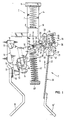
- the spring mechanism 1 lying in two housing half-shells, not shown, is actuated by a push button 3 which is longitudinally displaceable in the actuating direction 2.
- This is designed as an elongated sliding body 4, the handle end 5 of which protrudes from the housing. Its inner end 6 is arranged within the housing in the area of overlap with the spring mechanism 1.
- the push button 3 is acted upon in the switch-off direction by a switch-compression spring-like switch spring 7 acting in the region of its handle end 5.
- the switch-off spring 7 automatically pushes the push button 3 into the switch-off position shown in FIG. 1 when the spring mechanism 1 is triggered.
- the switch-off spring 7 is supported on a stop 8 fixed to the housing.
- Switching level is understood to mean the level in which the pivoting and displacement movements of the switch mechanism take place. In the exemplary embodiment shown, it essentially coincides with the plane of the drawing.
- the contact bridge support 9 which is designed as an angle lever, is arranged on the side of the inner end 6 of the push button 3. This consists essentially of a right-angled to the direction of actuation 2 of the push button 3, at its inner end 6 to the opposite side guide arm 10 and a substantially parallel to the direction of actuation 2 arranged support arm 11.
- At the free end 12 of the support arm 11 is the contact bridge 13 by means of a Contact bridge carrier 9 penetrating rivets 14 attached.
- the contact bridge 13 is arranged approximately at right angles to the switching plane and connects the two lateral fixed contacts 15 which are aligned with one another in this direction, of which only the one facing the viewer can be seen in the figures.
- the front fixed contact 15 is connected via a connecting lug 16 to the corresponding connecting line by means of a connecting terminal.
- the rear fixed contact is in conductive connection with the bimetal 39, which contacts via its connecting lug 16 ⁇ with the second connecting line.
- the connecting line and terminal for the connecting lug 16 and the rear fixed contact are omitted in the figures for the sake of clarity
- the contact bridge support 9 which is designed as an angle lever, has, in the transition region between its guide 10 and support arm 11, a bearing pin 17 arranged transversely to the switching plane, which is located in a side of the push button 3 parallel to its actuating direction 2 arranged guide groove 18 is guided.
- the contact bridge carrier 9 can carry out both a sliding movement and a pivoting movement in the switching plane.
- the guide groove 18 and the fixed contacts 15 are arranged essentially in an extension on a line parallel to the direction of actuation 2 of the push button 3.
- the locking device 19 of the spring mechanism 1 is arranged on the side of the push button 3 opposite these components.
- An axle journal 24 is formed transversely to the switching plane on the bearing end 23 of the release lever 20 pointing in the switching-off direction 22, which engages in a substantially parallel to the direction of actuation 2 of the push button 3 laterally next to this housing groove 25 and is guided there to be longitudinally displaceable.
- the trigger lever 20 can perform a pivoting movement in the switching plane around the journal 24.
- the free end of the release lever 20 is articulated as a hinge end 26 to the free end 27 of the guide arm 10 of the contact bridge support 9.
- the free end 27 engages between two spigots 28, 29 mounted transversely to the switching plane in the switching-off direction 22 and spaced on the release lever 20. These thus form a receiving opening 30 for the free end 27, which is tapered relative to the remaining width of the guide arm 10.
- the pin 28, which is closer to the journal 24, serves as the point of engagement of a helical tension spring 31, which is fastened to the contact arm support 9 by a pin 55 in the central region of the guide arm 10 is.
- the housing groove 25 is designed in the manner of an elongated hole and has an oblique offset 32 in its lower region, through which the lower end of the housing groove 25 is offset in the direction of the push button 3.
- the locking arm 33 of the T-shaped, three-armed locking lever 21 is arranged in the region of the oblique offset 32.
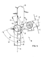
- This lever is pivotally supported by the pivot bearing 34 at the intersection of its T-horizontal and vertical legs. It is acted upon by the helical compression spring 35, which is supported on the housing via the stop 56, in the locking direction (i.e. clockwise in relation to the figure), which acts on its loading arm 36 facing away from the locking arm 33 (locking force V, see FIG. 5).
- the Latch 33 and loading arm 36 together form the T-horizontal leg of the locking lever 21.
- the T-vertical leg is formed by the actuating arm 37 lying approximately parallel to the direction of actuation 2 of the push button 3, on which the movement end 38 of the bimetal 39 acting as a thermal release element acts.
- the locking arm 33 is at its free end 40 in the region of the inclined offset 32 in overlap with the housing groove 25.
- the stop surface 41 which is designed as a cylinder segment surface arranged transversely to the switching plane, forms one at the free end 40 of the locking arm 33 and the opposite counter bevel 42 of the inclined offset 32 wedge-shaped against the opening direction 22 opening inner angle region 43, the function of which is clear from the explanation of the switching kinematic sequence of the spring mechanism 1.
- Fig. 1 the overcurrent protection switch is shown in its off position.
- the contact bridge support 9, the push button 3 and the release lever 20 are in their upper extreme position, the Contact bridge support 9 is slightly tilted counterclockwise around its bearing pin 17 with respect to FIG. 1.
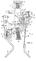
- the push button 3 (FIG. 2) is actuated, its latching lug 44, which is laterally attached to its inner end 6, engages in the latching recess 46 in the contact bridge carrier 9 on the rear side 45 facing away from the fixed contacts 14.
- the contact bridge support 9 is carried along against the loading force of the contact pressure spring 47 clamped between the guide arm 10 and a stop 48 fixed to the housing, approximately in the actuating direction 2.
- the contact bridge support 9 is only shifted longitudinally, but remains in its tilted state.
- the contacts acting on the locking device 19 in this position can be explained with reference to FIGS. 3 and 5.
- the contact pressure spring 47 provides not only the contact pressure itself, but also the breaking force tearing the contact bridge carrier 9 away from the fixed contacts 15 in the breaking direction 22.
- This switch-off force A is transmitted via the guide arm 10 to the release lever 20 and acts on it in the switch-off direction 22.
- the switch-off force A is broken down into two subcomponents F1, F2 in the manner of a force parallelogram.
- the subcomponent F2 acting on the stop surface 41 is reduced.
- the push button 3 can be held in its switched-on position, but the triggering movement of the contact bridge carrier is not influenced (free release).
- the locking recess 46 can namely no longer come into engagement with the locking lug 44 of the push button, as a result of which the switch-off movement could be prevented.
- the manual switch-off via the push button 3 is explained with reference to FIG. 3.
- the trigger lever 20 is under the influence of the tension spring 31 with its pin 28 on the locking device 19 facing side edge 51 of the push button 3.
- a run-up slope 52 is formed on this side edge 51, which forms an obtuse angle with the side edge 51.
- the defined on-position of the push button 3 shown in FIG. 3 is achieved by inserting the axle pin 24 of the release lever 20 in the angular range between the side edge 51 and the support slope 52 maintained.
- the torque applied by the tension coil spring 31 and exerted transversely to the actuating direction 2 on the release lever 20 is namely greater than the counter torque transmitted to the release lever 20 by the switch-off spring 7 via the bevel 52.
Landscapes
- Breakers (AREA)
- Thermally Actuated Switches (AREA)
Abstract
Description
Die Erfindung betrifft einen Überstromschutzschalter mit den im Oberbegriff des Anspruches 1 angegebenen Merkmalen.The invention relates to an overcurrent protection switch with the features specified in the preamble of
Das Sprungwerk oder Schaltschloß eines Überstromschutzschalters weist im wesentlichen ein bewegliches Kontaktstück auf, das durch seine Anlage an einem oder mehreren Festkontakten die Schaltstrecke des Schalters schließt. Um im Überstromfall ein schnelles Abschalten des Stromes zu gewährleisten, ist das bewegliche Kontaktstück direkt oder über gelenkig damit verbundene Schaltschloßteile in Ausschaltrichtung federbeaufschlagt. In seiner Ausschaltstellung ist das Kontaktstück direkt oder über gelenkig mit ihm verbundene Bauelemente des Schaltschlosses - hier der sogenannte Auslöseschieber - mittels eines Riegelhebels verriegelt. Dieser ist in seine Verriegelungsstellung verschwenkbar und durch ein thermisches und/oder elektromagnetisches Auslöseorgan oder durch die Betätigungshandhabe des Schalters gegen eine Rückstellkraft in seine Entriegelungsstellung verschwenkbar. Die Fixierung des beweglichen Kontaktstückes in seiner Einschaltstellung erfolgt durch Abstützung des gelenkig mit dem beweglichen Kontaktstück verbundenen Auslöseschiebers an einer Anschlagfläche des in seiner Verriegelungsstellung in die definierte Bewegungsbahn des Auslöseschiebers hineinragenden Endes des Riegelhebels. Die Bewegungsbahn des Auslöseschiebers kann dabei durch dessen Führung in einer Gehäusenut od.dgl. hervorgerufen werden. Denkbar ist auch eine gelenkkettenartige Kopplung des Auslöseschiebers, mit dem eine konstruktionsbedingte Ein-Ausschaltbewegung des beweglichen Kontaktstückes auf den Auslöseschieber übertragbar ist. Wichtig ist lediglich, daß letzterer bei der Ein-Ausschaltbewegung einen in Lage und Richtung definierten Weg zurücklegt.The spring mechanism or switch lock of an overcurrent protection switch essentially has a movable contact piece which closes the switching path of the switch due to its contact with one or more fixed contacts. In order to ensure that the current is switched off quickly in the event of an overcurrent, the movable contact piece is spring-loaded in the switch-off direction, either directly or via articulated switching lock parts. In its switched-off position, the contact piece is locked directly or by means of components of the switch lock which are connected to it in an articulated manner - here the so-called trigger slide - by means of a locking lever. This can be pivoted into its locking position and can be pivoted into its unlocking position against a restoring force by a thermal and / or electromagnetic release element or by the actuating handle of the switch. The movable contact piece is fixed in its switched-on position by supporting the trigger slide articulated to the movable contact piece on a stop surface of the end of the locking lever which projects into the defined movement path of the trigger slide in its locking position. The path of movement of the trigger slide can or the like by guiding it in a housing groove. are caused. A link chain-like coupling is also conceivable of the trigger slide, with which a design-related on-off movement of the movable contact piece can be transmitted to the trigger slide. It is only important that the latter cover a path and direction defined when the switch is turned on and off.
Grundsätzlich sind von den Überstrom-Auslöseorganen des Sprungwerks zur Verschwenkung des Riegelhebels in seine Entriegelungsstellung Auslösekräfte aufzubringen. Bei der Entriegelung müssen nämlich Gegenkräfte überwunden werden, die sich unter anderem aus Reibungskräften an der Verriegelungsstelle und am Riegelhebel angreifenden, aus dessen Federbeaufschlagung in Verriegelungsrichtung resultierenden Hebelkräften zusammensetzen. Um ein schnelles Ansprechen des Überstromschutzschalters und damit hohe Schaltleistungen zu gewährleisten, sollen diese Gegen- und damit die von den Überstromauslösern aufzubringenden Auslösekräfte möglichst klein gehalten werden.Basically, the overcurrent release elements of the spring mechanism for pivoting the locking lever into its unlocking position must apply release forces. When unlocking, counter forces have to be overcome, which are composed, among other things, of frictional forces acting on the locking point and on the locking lever, resulting from its spring action in the locking direction. In order to ensure a quick response of the overcurrent protection switch and thus high switching capacities, these counter-forces and thus the triggering forces to be applied by the overcurrent releases should be kept as small as possible.
Bei bekannten Lösungen für dieses Problem nach dem Stande der Technik ist es beispielsweise üblich, die Kontakt- und Ausschaltkräfte über ein Kniehebelsystem zu untersetzen. Damit werden zwar befriedigende Ergebnisse bezüglich der Höhe der aufzubringenden Auslösekräfte erzielt, jedoch sind Kniehebelsysteme konstruktiv aufwendig mit entsprechend hohem Bauteile- und Montageaufwand für das Sprungwerk.In known solutions to this problem according to the prior art, it is customary, for example, to reduce the contact and switch-off forces via a toggle lever system. Although this achieves satisfactory results with regard to the level of the triggering forces to be applied, toggle lever systems are structurally complex with a correspondingly high amount of components and assembly work for the jumping mechanism.
Davon ausgehend liegt der Erfindung die Aufgabe zugrunde, einen Überstromschutzschalter mit einer Verriegelungsvorrichtung für sein Sprungwerk anzugeben, bei dem mit einfachen konstruktiven Mitteln die von den Auslöseorganen aufzubringenden Auslösekräfte besonders klein gehalten werden.Proceeding from this, the object of the invention is to provide an overcurrent protection switch with a locking device for its spring mechanism, in which the triggering forces to be applied by the triggering elements are kept particularly small with simple constructional means.
Diese Aufgabe wird gemäß den kennzeichnenden Merkmalen des Anspruches 1 gelöst. Demnach wird eine Untersetzung der auf die Verriegelungsstelle wirkenden Gesamtkraft durch deren Zerlegung in zwei Teilkomponenten erreicht. Der Auslöseschieber liegt nämlich mit seinem in Ausschaltrichtung weisenden Ende an der Anschlagfläche des Riegelhebels und zusätzlich an einer gehäusefesten Gegenschräge in seiner Bewegungsbahn an. Die Anschlagfläche des Riegelhebels und die Gegenschräge bilden dabei einen keilförmigen, sich gegen die Ausschaltrichtung des Auslöseschiebers öffnenden Innenwinkelbereich. Die Gesamtkraft wird also nach Art eines Kräfteparallelogramms zerlegt und wirkt teils auf die Gegenschräge und nur mit einem Bruchteil auf die eigentliche Verriegelungsstelle zwisc Auslöseschieber und Riegelhebel. Die Verriegelungsstelle wird also mit einer geringeren Kraft belastet, wodurch sich die Reibungs- und Hebelkräfte erheblich reduzieren.This object is achieved in accordance with the characterizing features of
Die Unteransprüche 2 bis 6 betreffen vorteilhafte Weiterbildungen der erfindungsgemäßen Verriegelungsvorrichtung. Nach Anspruch 2 ist die gehäusefeste Gegenschräge in einem größeren Winkel zur Ausschaltrichtung angeordnet als die Anschlagfläche des Riegelhebels. Dadurch wird die Kraftzerlegung in Teilkomponenten zu Gunsten einer geringeren Kraftbeaufschlagung auf die Anschlagfläche verschoben. Wird diese Maßnahme insbesondere kombiniert mit einer Ausgestaltung des Erfindungsgegenstandes gemäß Anspruch 3, so ergeben sich besonders günstige Kraftverhältnisse bei der Verriegelungsvorrichtung. Bilden nämlich die gehäusefeste Gegenschräge und die Anschlagfläche des Riegelhebels einen stumpfen Innenwinkelbereich von etwa 90° - also beispielsweise zwischen 75° und 105° - und ist gleichzeitig die Gegenschräge in einem größeren Winkel, beispielsweise in einem viermal so großen Winkel wie die Anschlagfläche zur Ausschaltrichtung angeord net, so wird ein hoher Anteil der Ausschaltkräfte über die Gehäuseschräge abgestützt. Die verbleibende, auf die Verriegelungsstelle wirkende Kraftkomponente wird also weiter reduziert. Diese ist durch die Geometrie jedoch noch so hoch, daß nach dem Verschwenken des Riegelhebels in seine Entriegelungsstellung der Auslöseschieber unter Einfluß dieser Teilkomponente an der Gegenschräge abgleiten und mit dem Kontaktstück in die Ausschaltstellung des Sprungwerkes übergeführt werden kann.The
Im Anspruch 4 ist eine vorteilhafte Form für das Abstützende des Auslöseschiebers angegeben. Durch dessen Ausbildung als in einer langlochartigen Gehäusenut geführter Achszapfen ist eine Doppelfunktion erzielt. An seinem Abstützende ist der Auslöseschieber nämlich entlang einer definierten Bewegungsbahn geführt, zum zweiten ergeben sich durch die Zapfenform zwei punkt- oder zumindest linienförmige Anlagebereiche des Auslöseschiebers an der Gegenschräge bzw. der Anschlagfläche des Riegelhebels. Damit sind die Angriffspunkte der Teilkomponenten der Ausschaltkraft eindeutig festgelegt und es ergeben sich definierte, von Schaltzyklus zu Schaltzyklus reproduzierbare Kraftverhältnisse. Darüber hinaus stellt eine Gehäusenut eine konstruktiv denkbar einfache Maßnahme dar, um die Führung eines beweglichen Bauteiles entlang einer bestimmten Bahn zu erzielen.In claim 4, an advantageous shape for the support end of the trigger slide is specified. By designing it as an axle journal guided in a slot-like housing groove, a double function is achieved. At its support end, the release slide is guided along a defined movement path, and secondly, the pin shape results in two point-shaped or at least linear contact areas of the release slide on the counter slope or the stop surface of the locking lever. The points of application of the sub-components of the breaking force are thus clearly defined and there are defined force ratios that can be reproduced from switching cycle to switching cycle. In addition, a housing groove is a structurally simple measure to achieve the guidance of a movable component along a certain path.
Im Kennzeichen des Anspruches 5 ist eine vorteilhafte Ausgestaltung der Gehäusenut angegeben. Die gehäusefeste Gegenschräge wird demgemäß nämlich auf einfache Weise durch einen im Überdeckungsbereich mit dem Riegelhebelende angeordneten, von diesem weggerichteten Schrägversatz der Gehäusenut gebildet. Der Schrägversatz selbst kann dabei als ebene Fläche unter einem stumpfen Winkel in die beidseitig angrenzenden geradlinigen Bereiche der Gehäusenut übergehen, jedoch ist auch ein flacher, S-förmig geschwungener Verlauf denkbar.In the characterizing part of
Anspruch 6 lehrt eine Maßnahme, mit der zusätzliche, von den Auslösekräften der Auslöseorgane zu überwindende Hebelkräfte bei der Verschwenkung des Riegelhebels in seine Entriegelungsstellung vermieden werden. Dessen Anschlagfläche ist nämlich als konvexe Zylindersegmentfläche ausgebildet, deren Radius im wesentlichen dem Abstand der Anschlagfläche vom Drehlagerpunkt des Riegelhebels entspricht. Dadurch ändert sich der Lageabstand des Achszapfens vom Drehlagerpunkt des Riegelhebels nicht, wenn dieser verschwenkt wird. Würde sich dieser vergrößern, so müßten die Auslöseorgane nämlich eine zusätzliche Kraftkomponente überwinden, die aus der Verschiebung des Achszapfens entgegen der auf den Auslöseschieber gegebenenfalls über das bewegliche Kontaktstück wirkenden Ausschaltkraft herrührt.
Die weiteren Ansprüche 7 bis 15 betreffen vorteilhafte Ausgestaltungen des Erfindungsgegenstandes für einen druckknopfbetätigten Überstromschutzschalter. Dieser ist damit im wesentlichen eine Weiterentwicklung des druckknopfbetätigten Überstromschutzschalters mit thermischer Auslösung gemäß DE-PS 25 02 579. Der bekannte Überstromschutzschalter ist mit einer Momentein-, -ausschaltung, thermischer sowie einer Freiauslösung versehen. Er weist einen als zweiarmigen Winkelhebel ausgebildeten, in der Schaltebene schwenk- und verschiebbaren Kontaktbrückenträger auf, der einen im wesentlichen rechtwinklig zur Betätigungsrichtung des Druckknopfes angeordneten, entgegen dieser Richtung federbelasteten Führungsarm und einen im wesentlichen parallel zu dieser Richtung seitlich vom Druckknopf angeordneten Trägerarm auf. Am Freiende des Trägerarmes ist die Kontaktbrücke zur Kontaktverbindung zwischen zwei Festkontakten befestigt. Der Trägerarm ist mit dem inneren Ende des Druckknopfes zur Übertragung dessen Einschaltbewegung auf den Kontaktbrückenträger verklinkbar. Durch die in der angegebenen Druckschrift gezeigte Verklinkungsweise wird eine schlagartige Momenteinschaltung der Kontaktbrücke erreicht.The further claims 7 to 15 relate to advantageous refinements of the subject matter of the invention for a push-button-operated overcurrent protection switch. This is essentially a further development of the push-button-operated overcurrent protection switch with thermal tripping in accordance with DE-PS 25 02 579. The known overcurrent protection switch is provided with a momentary on / off switch, thermal as well as a free release. It has a contact arm carrier designed as a two-armed angle lever, which can be pivoted and displaced in the switching plane, which has a guide arm which is arranged essentially at right angles to the direction of actuation of the push button and is spring-loaded against this direction, and a support arm which is arranged essentially parallel to this direction to the side of the push button. At the free end the support arm, the contact bridge for contact connection between two fixed contacts is attached. The support arm can be latched to the inner end of the push button for transmitting its switch-on movement to the contact bridge support. Due to the latching method shown in the specified publication, an abrupt moment switching on of the contact bridge is achieved.
Bei dem bekannten Überstromschutzschalter wirkt die von der Ausschaltfeder hervorgerufene Beaufschlagungskraft in Ausschaltrichtung in ihrer vollen Höhe auf die Verklinkungsstelle des Kontaktbrückenträgers mit dem Rastvorsprung am Bewegungsende des Bimetalls. Dieser Konstruktion sind die eingangs genannten Nachteile zu eigen.In the known overcurrent protection switch, the loading force caused by the switch-off spring acts in its switch-off direction in its full height on the latching point of the contact bridge support with the locking projection at the end of the movement of the bimetal. This construction has the disadvantages mentioned at the outset.
Durch das Übergreifen des Führungsarmes des Kontaktbrückenträgers über den Druckknopf im Gehäuseinnern und durch die gelenkige Verbindung des Führungsarm-Freiendes mit dem entlang einer parallel zur Betätigungsrichtung des Druckknopfes verlaufenden Bewegungsbahn verschiebbaren Auslöseschieber der Verriegelungsvorrichtung wird der bekannte Überstromschutzschalter derart weitergebildet, daß die von den Überstrom-Auslöseorganen aufzubringenden Auslösekräfte besonders gering sind. Dadurch verkürzt sich die Auslösezeit des erfindungsgemäßen Überstromschutzschalters und es kann eine erhöhte Abschaltleistung erzielt werden. Darüber hinaus unterliegt die Verriegelungsvorrichtung durch die reduzierten Reibungskräfte an den gegenseitigen Anlageflächen einem geringeren Verschleiß. Abrieb, Materialverformungen u.dgl. innerhalb des Sprungwerks werden damit vermieden oder zumindest stark unterdrückt, wodurch sich die Lebensdauer des Überstromschutzschalters erhöht sowie enge Auslösetoleranzen über eine längere Betriebsdauer eingehalten werden können.By overlapping the guide arm of the contact bridge support via the push button in the housing interior and by the articulated connection of the free end of the guide arm with the sliding slide of the locking device running along a movement path parallel to the actuating direction of the push button, the known overcurrent protection switch is developed in such a way that the overcurrent release elements trigger forces to be applied are particularly low. This shortens the tripping time of the overcurrent protection switch according to the invention and an increased breaking capacity can be achieved. In addition, the locking device is subject to less wear due to the reduced frictional forces on the mutual contact surfaces. Abrasion, material deformation and the like. This avoids or at least strongly suppresses within the spring mechanism, which increases the service life of the overcurrent protection switch and allows close tripping tolerances to be maintained over a longer operating period.
Durch eine Ausbildung des Überstromschutzschalters gemäß dem Kennzeichen des Anspruches 8 wird aus dem Auslöseschieber mit einfachen konstruktiven Mitteln ein einarmiger Auslösehebel, der im wesentlichen parallel zur Gehäusenut angeordnet und dessen Drehachse sein in der Gehäusenut längsverschiebbarer Achszapfen ist. Durch diese Ausgestaltung können dem Auslösehebel weitere, im folgenden definierte Funktionen zugewiesen werden.By designing the overcurrent protection switch according to the characterizing part of
Um die Schwenkbarkeit des Auslösehebels zu ermöglichen, muß die gelenkige Verbindung zwischen dem Führungsarm des Kontaktbrückenträgers und dem Auslösehebel eine gegenseitige Verschiebung dieser beiden Teile in Drehrichtung des Auslösehebels ermöglichen. Entsprechend ist gemäß Anspruch 9 die gelenkige Verbindung durch den Eingriff des Führungsarm-Freiendes in eine rechtwinklig zur Betätigungsrichtung verlaufende Aufnahmeöffnung am dem Achszapfen gegenüberliegenden Gelenkende des Auslösehebels gebildet. Der Eingriff erfolgt vorzugsweise unter Spiel, wodurch der Auslösehebel zwar zuverlässig bei der Einschaltbewegung vom Kontaktbrückenträger mitgeführt wird, jedoch die genannte Drehbewegung des Auslösehebels um seinen Achszapfen in gewissen Grenzen möglich ist.In order to allow the pivoting of the release lever, the articulated connection between the guide arm of the contact bridge support and the release lever must allow a mutual displacement of these two parts in the direction of rotation of the release lever. Correspondingly, according to
Im Kennzeichen des Anspruches 10 sind die Maßnahmen angegeben, mit denen eine vorteilhafte Zusatzfunktion durch den Auslösehebel wahrnehmbar ist. Der Riegelhebel der Verriegelungsvorrichtung weist nämlich einen etwa parallel neben dem Auslösehebel in dessen Schwenkbereich verlaufenden Betätigungsarm auf, mittels dem der Riegelhebel aus seiner Verriegelungsstellung vom Auslösehebel durch dessen Schwenkung um den Achszap fen in die Entriegelungsstellung verbringbar ist. Dies bedeutet, daß die Betätigungshandhabe bzw. thermischen und/oder elektromagnetischen Auslöseorgane auf verschiedene Bauelemente des Sprungwerkes einwirken können, um eine Entriegelung des Sprungwerkes zu erzielen. Beispielsweise kann das Bewegungsende des Bimetalls direkt den Riegelhebel, dessen Betätigungsarm oder sogar den Auslösehebel in Entriegelungsrichtung beaufschlagen. Es bleibt dem Konstrukteur überlassen, an welcher Stelle er beispielsweise das Bimetall in ihm vorteilhaft erscheinender Weise anordnet. Durch die erfindungsgemäße Ausgestaltung bleiben ihm hier verschiedene Wahlmöglichkeiten, wie er das entsprechende Auslöseorgan anordnet und auf welche Weise er es auf die Verriegelungsvorrichtung einwirken läßt.In the characterizing part of
Im Anspruch 11 ist eine mögliche Ausgestaltung des Erfindungsgegenstandes angegeben, nach der der Auslösehebel in seiner Verriegelungsstellung durch Betätigung des Druckknopfes in Entriegelungsrichtung um seinen Achszapfen verschwenkbar ist. Diese Verschwenkung kann auf den Riegelhebel übertragen werden, der dadurch seinerseits in die Entriegelungsstellung überführbar ist und die Verriegelung des Auslösehebels und damit den Kontaktbrückenträger frei gibt. Da somit der Druckknopf und das thermische Auslöseorgan an verschiedenen Bauteilen des Sprungwerkes angreifen können, ist eine vorteilhafte funktionale Gliederung des Sprungwerkaufbaues und damit eine konstruktive Vereinfachung erreicht.
Die in Anspruch 12 genannte Maßnahme stellt eine besonders einfache Möglichkeit zur Bildung der Aufnahmeöffnung des Auslösehebels für das Freiende des Führungsarmes dar. Die Zapfen zur Bildung der Aufnahmeöffnung können dabei weitere Aufgaben übernehmen, wie dies in Anspruch 13 angegeben ist. Der dem Achszapfen zugewandte, innere der beiden Zapfen ist von einer am Führungsarm des Kontaktbrückenträgers befestigten Zugfeder etwa rechtwinklig zur Betätigungsrichtung des Druckknopfes derart beaufschlagt, daß er dadurch ständig an der der Verriegelungsvorrichtung zugewandten, parallel zur Betätigungsrichtung verlaufenden Seitenkante des Druckknopfes anliegt. Damit nimmt der Auslösehebel trotz seiner möglichen Drehbarkeit um seinen Achszapfen in jeder Schaltstellung des Sprungwerkes eine definierte Lage ein. Durch die Eindeutigkeit der Lagebeziehung zwischen der Seitenkante des Druckknopfes und dem inneren Zapfen des Auslösehebels kann die Seitenkante zu Steuerungsaufgaben für die Drehbewegung des Auslösehebels verwendet werden. Entsprechend ist gemäß Anspruch 14 an diese Seitenkante des Druckknopfes eine mit dessen Betätigungsrichtung einen stumpfen Winkel bildende Auflaufschräge angeformt, über die bei der Ausschalt-Betätigung des Druckknopfes der Auslösehebel und über diesen der Riegelhebel in Entriegelungsrichtung beaufschlagbar sind. Die Steuerung einer Drehbewegung über eine Auflaufschräge stellt dabei eine konstruktiv besonders einfache Lösung dar.The measure mentioned in
Die seitlichen, einander zugewandten Anschlagvorsprünge am Auslösehebel und am Betätigungsarm des Riegelhebels gewährleisten eine unverzügliche Übertragung der Schwenkbewegung des Auslösehebels auf den Riegelhebel.The side, mutually facing stop projections on the release lever and on the actuating arm of the locking lever ensure immediate transmission of the pivoting movement of the release lever to the locking lever.
In der Summe der Erfindungsvorteile wird ein Überstromschutzschalter geschaffen, der konstruktiv einfach aufgebaut, klar gegliedert ist und demzufolge sehr kompakt baut, dabei jedoch alle schalttechnischen Vorzüge wie Momentein-, -ausschaltung und Freiauslösung aufweist und darüber hinaus eine hohe Abschaltleistung bei toleranzengem Langzeit-Schaltverhalten erzielt.In the sum of the advantages of the invention, an overcurrent protection switch is created which is structurally simple in construction, clearly structured and consequently very compact in construction, but all switching technology Has advantages such as instantaneous switching on and off and free tripping and also achieves a high switch-off power with tolerant long-term switching behavior.
Die Erfindung wird in einem Ausführungsbeispiel anhand der beiliegenden Figuren näher erläutert. Es zeigen:
- Fig. 1 eine schematische Ansicht des Überstromschutzschalters mit Sprungwerk und Druckknopf in Aus-Stellung,
- Fig. 2 eine Ansicht gemäß Fig. 1 kurz vor Erreichen der Ein-Stellung,
- Fig. 3 eine Ansicht gemäß Fig. 1 in der verriegelten Ein-Stellung des Schalters,
- Fig. 4 eine Ans icht gemäß Fig. 1 in der Stellung "Freiauslösung" und
- Fig. 5 eine Prinzipskizze der Verriegelungsvorrichtung des Überstromschutzschalters.
- 1 is a schematic view of the overcurrent protection switch with spring mechanism and push button in the off position,
- 2 is a view of FIG. 1 shortly before reaching the on position,
- 3 is a view of FIG. 1 in the locked on position of the switch,
- Fig. 4 is a view according to FIG. 1 in the "free trip" position and
- Fig. 5 is a schematic diagram of the locking device of the overcurrent protection switch.
Das in zwei nicht dargestellten Gehäusehalbschalen einliegende Sprungwerk 1 wird von einem in Betätigungsrichtung 2 längsverschiebbaren Druckknopf 3 betätigt. Dieser ist als langgestreckter Schiebekörper 4 ausgebildet, dessen Griffende 5 aus dem Gehäuse heraussteht. Sein Innenende 6 ist innerhalb des Gehäuses im Überdeckungsbereich mit dem Sprungwerk 1 angeordnet. Der Druckknopf 3 ist durch eine im Bereich seines Griffendes 5 angreifende, schraubendruckfederartige Ausschaltfeder 7 in Ausschaltrichtung beaufschlagt. Die Ausschaltfeder 7 führt den Druckknopf 3 bei ausgelöstem Sprungwerk 1 selbsttätig in die in Fig. 1 gezeigte Ausschaltstellung über. Dazu stützt sich die Ausschaltfeder 7 an einem gehäusefesten Anschlag 8 ab.The
Anhand der Fig. 1 werden die im wesentlichen in der Schaltebene nebeneinanderliegenden, hauptsächlichen Bauteile des Sprungwerkes 1 beschrieben. Unter Schaltebene ist dabei die Ebene zu verstehen, in der die Schwenk- und Verschiebebewegungen der Schaltermechanik ablaufen. Sie fällt im gezeigten Ausführungsbeispiel im wesentlichen mit der Zeichnungsebene zusammen. Seitlich des Innenendes 6 des Druckknopfes 3 ist der als Winkelhebel ausgebildete Kontaktbrückenträger 9 angeordnet. Dieser besteht im wesentlichen aus einem rechtwinklig zur Betätigungsrichtung 2 des Druckknopfes 3 angeordneten, an dessen Innenende 6 zur gegenüberliegenden Seite vorbeigeführten Führungsarm 10 und einem im wesentlichen parallel zur Betätigungsrichtung 2 angeordneten Trägerarm 11. Am Freiende 12 des Trägerarmes 11 ist die Kontaktbrücke 13 mittels eines den Kontaktbrückenträger 9 durchsetzenden Nietes 14 befestigt. Die Kontaktbrücke 13 ist etwa rechtwinklig zur Schaltebene angeordnet und verbindet die beiden in dieser Richtung miteinander fluchtenden, seitlichen Festkontakte 15, von denen in den Figuren jeweils nur der dem Betrachter zugewandte erkennbar ist. Der vordere Festkontakt 15 ist über eine Anschlußfahne 16 mit der entsprechenden Anschlußleitung mittels einer Anschlußklemme verbunden. Der hintere Festkontakt steht in leitender Verbindung mit dem Bimetall 39, das über seine Anschlußfahne 16ʹ mit der zweiten Anschlußleitung kontaktiert. Die Anschlußleitung und -klemme für die Anschlußfahne 16 sowie der hintere Festkontakt sind in den Figuren der Übersichtlichkeit halber weggelassen1, the main components of the
Der als Winkelhebel ausgebildete Kontaktbrückenträger 9 weist im Übergangsbereich zwischen seinem Führungs-10 und Trägerarm 11 einen quer zur Schaltebene angeordneten Lagerzapfen 17 auf, der in einer seitlich vom Druckknopf 3 parallel zu dessen Betätigungsrichtung 2 angeordneten Führungsnut 18 verschiebbar geführt ist. Entsprechend kann der Kontaktbrückenträger 9 sowohl eine Schiebebewegung als auch eine Schwenkbewegung in der Schaltebene vollziehen. Die Führungsnut 18 und die Festkontakte 15 sind dabei im wesentlichen in Verlängerung auf einer Linie parallel zur Betätigungsrichtung 2 des Druckknopfes 3 angeordnet. Auf der diesen Bauteilen gegenüberliegenden Seite des Druckknopfes 3 ist die Verriegelungsvorrichtung 19 des Sprungwerks 1 angeordnet. Diese besteht im wesentlichen aus einem parallel zur Betätigungsrichtung 2 direkt neben dem Druckknopf 3 angeordneten, einarmigen Auslösehebel 20 und einem danebenliegenden, T-förmigen Riegelhebel 21. An das in Ausschaltrichtung 22 weisende Lagerende 23 des Auslösehebels 20 ist quer zur Schaltebene ein Achszapfen 24 angeformt, der in eine im wesentlichen parallel zur Betätigungsrichtung 2 des Druckknopfes 3 seitlich neben diesem verlaufenden Gehäusenut 25 eingreift und dort längsverschiebbar geführt ist. Der Auslösehebel 20 kann um den Achszapfen 24 eine Schwenkbewegung in der Schaltebene ausführen. Das Freiende des Auslösehebels 20 ist als Gelenkende 26 gelenkig mit dem Freiende 27 des Führungsarmes 10 des Kontaktbrückenträgers 9 verbunden. Dazu greift das Freiende 27 zw ischen zwei quer zur Schaltebene in Ausschaltrichtung 22 beabstandet am Auslösehebel 20 angebrachte Zapfen 28,29 ein. Diese bilden damit eine Aufnahmeöffnung 30 für das gegenüber der restlichen Breite des Führungsarmes 10 verjüngte Freiende 27. Der näher zum Achszapfen 24 liegende Zapfen 28 dient als Angriffspunkt einer Schraubenzugfeder 31, die im Mittenbereich des Führungsarmes 10 des Kontaktbrückenträgers 9 an diesem durch einen Stift 55 befestigt ist.The
Die Gehäusenut 25 ist langlochartig ausgebildet und weist in ihrem unteren Bereich einen Schrägversatz 32 auf, durch den das untere Ende der Gehäusenut 25 in Richtung auf den Druckknopf 3 versetzt ist. Im Bereich des Schrägversatzes 32 ist der Riegelarm 33 des T-förmigen, dreiarmigen Riegelhebels 21 angeordnet. Dieser Hebel ist am Schnittpunkt seines T-Horizontal- und -Vertikalschenkels durch das Drehlager 34 verschwenkbar gelagert. Er ist durch die sich am Gehäuse über den Anschlag 56 abstützende Schraubendruckfeder 35 in Verriegelungsrichtung (d.h. bezgl. den Fign. im Uhrzeigersinn) beaufschlagt, die an seinem dem Riegelarm 33 abgewandten Beaufschlagungsarm 36 angreift (Verriegelungskraft V, s.Fig.5). Riegel-33 und Beaufschlagungsarm 36 bilden gemeinsam den T-Horizontalschenkel des Riegelhebels 21. Der T-Vertikalschenkel ist durch den etwa parallel zur Betätigungsrichtung 2 des Druckknopfes 3 liegenden Betätigungsarm 37 gebildet, an dem das Bewegungsende 38 des als thermisches Auslöseorgan fungierenden Bimetalls 39 angreift. Der Riegelarm 33 steht mit seinem Freiende 40 im Bereich des Schrägversatzes 32 in Überdeckung mit der Gehäusenut 25. In der Verriegelungsstellung bildet dabei die als quer zur Schaltebene angeordnete Zylindersegmentfläche ausgebildete Anschlagfläche 41 am Freiende 40 des Riegelarmes 33 und die gegenüberliegende Gegenschräge 42 des Schrägversatzes 32 einen sich keilförmig gegen die Ausschaltrichtung 22 öffnenden Innenwinkelbereich 43, dessen Funktion anhand der Erklärung des schaltkinematischen Ablaufes des Sprungwerks 1 klar wird.The
In Fig. 1 ist der Überstromschutzschalter in seiner Aus-Stellung gezeigt. Der Kontaktbrückenträger 9, der Druckknopf 3 sowie der Auslösehebel 20 befinden sich in ihrer oberen Extremalstellung, wobei der Kontaktbrückenträger 9 leicht um seinen Lagerzapfen 17 entgegen dem Uhrzeigersinn bezogen auf Fig. 1 verkippt ist. Bei einer Betätigung des Druckknopfes 3 (Fig. 2) greift dessen seitlich an seinem Innenende 6 angebrachte Rastnase 44 in die auf der den Festkontakten 14 abgewandten Rückseite 45 angebrachte Rastausnehmung 46 des Kontaktbrückenträgers 9 ein. Dadurch wird der Kontaktbrückenträger 9 entgegen der Beaufschlagungskraft der etwa in Betätigungsrichtung 2 zwischen den Führungsarm 10 und einem gehäusefesten Anschlag 48 eingespannten Kontaktdruckfeder 47 mitgeführt. Der Kontaktbrückenträger 9 wird dabei nur längsverschoben, verbleibt jedoch in seinem verkippten Zustand. Durch seine Längsverschiebung nimmt er den Auslösehebel 20 mit, wodurch sich dessen Achszapfen 24 in der Gehäusenut 25 nach unten bewegt. Dabei wird bei Durchlaufen des Schrägversatzes 32 der Riegelarm 33 des Riegelhebels 21 kurzzeitig entgegen der Beaufschlagung durch die Schraubendruckfeder 35 in seine Entriegelungsstellung außer Überdeckung mit der Gehäusenut 25 verbracht (nicht gezeigt) und der Achszapfen 24 überschnappt den Riegelhebel 21. Der Druckknopf wird so lange in das Gehäuse geschoben, bis die in Fig. 2 gezeigte Extremalstellung erreicht ist. Dabei liegt die Kontaktbrücke 13 noch nicht an den Festkontakten 15 an, die Kontaktdruckfeder 47 ist maximal gespannt und der Riegelhebel 21 ist unter Einfluß der Schraubendruckfeder 35 wieder in seine Verriegelungsstellung in Überdeckung mit der Gehäusenut 25 verbracht worden.In Fig. 1 the overcurrent protection switch is shown in its off position. The
Wird der Druckknopf 3 (Fig. 3) losgelassen, so bewegen sich die Teile der Sprungwerkmechanik in Ausschaltrichtung 22 zurück. Dies erfolgt jedoch nur solange, bis der Achszapfen 24 im von der Anschlagfläche 41 und der Gegenschräge 42 gebildeten Innenwinkelbere ich 43 (vgl. Fig. 5) anschlägt und dort verriegelt wird. Damit wirkt der innere Zapfen 28 des Auslösehebels als fester Drehpunkt für den Kontaktbrückenträger 9, der sich unter Einfluß der Kontaktdruckfeder 47 nun im Uhrzeigersinn verkippt, wobei sich der Druckknopf 3 über eine kurze Wegstrecke in Ausschaltrichtung 22 gegenüber dem Kontaktbrückenträger 9 verschieben kann. Die Rastnase 44 des Druckknopfes 3 gerät damit nach kurzer Zeit außer Eingriff mit der Rastausnehmung 46 am Kontaktbrückenträger 9, wodurch dann letzterer schlagartig in die in Fig. 3 gezeigte Ein-Stellung verschoben wird. Der erfindungsgemäße Überstromschutzschalter gewährleistet also eine handunabhängige Momenteinschaltung.When the push button 3 (FIG. 3) is released, the parts of the spring mechanism move back in the switch-
Die in dieser Stellung auf die Verriegelungsvorrichtung 19 wirkenden Kräfte sind anhand der Fig. 3 und 5 erläuterbar. Die Kontaktdruckfeder 47 stellt nicht nur den Kontaktdruck selbst, sondern auch die den Kontaktbrückenträger 9 von den Festkontakten 15 wegreißende Ausschaltkraft in Ausschaltrichtung 22 zur Verfügung. Diese Ausschaltkraft A wird über den Führungsarm 10 auf den Auslösehebel 20 übertragen und beaufschlagt diesen in Ausschaltrichtung 22. Durch die Anlage des Achszapfens 24 am Innenwinkelbereich 43 wird die Ausschaltkraft A nach Art eines Kräfteparallelogramms in zwei Teilkomponenten F1, F2 zerlegt. Durch die Anordnung der Gegenschräge 42 und der Anschlagfläche 41 in einem Winkel von ca. 80° gem. Fig. 5 zueinander wird die auf die Anschlagfläche 41 wirkende Teilkomponente F2 reduziert. Verstärkt wird dieser Effekt durch die Maßnahme, daß der Winkel 49 von ca. 64° zwischen Gegenschräge 42 und Ausschaltrichtung 22 wesentlich größer ist als der Winkel 50 von ca. 15° zwischen der Anschlagfläche 41 und dieser Richtung 22. Durch die Herabsetzung der Teilkomponente F2 reduzieren sich die Reibungskräfte zwischen dem Achszapfen 24 und dem Riegelhebel 21, womit geringere Entriegelungskräfte E vom Auslöseorgan aufgebracht werden müssen. In dem Ausführungsbeispiel gemäß Fig. 3 bedeutet dies, daß das Bimetall 39 eine geringere Auslösekraft zur Verfügung stellen muß. Die thermische Auslösung des Sprungwerkes 1 erfolgt auf einfache Weise, indem das Bimetall 39 durch eine temperaturbedingte Verbiegung (nicht gezeigt) den Anschlagvorsprung 57 am Betätigungsarm 37 beaufschlagt und den Riegelhebel 21 entgegen dem Uhrzeigersinn in Fig. 3 um Drehlager 34 verschwenkt, wodurch sich die Anschlagfläche 41 aus ihrer Überdeckung mit der Gehäusenut 25 herausbewegt. Der Achszapfen 24 kann damit am Riegelhebel 21 vorbeigleiten, wodurch der Auslösehebel 20 und damit der Kontaktbrückenträger 9 freigegeben und unter Einfluß der Kontaktdruckfeder 47 in die in Fig. 4 gezeigte Ausschaltstellung verbracht wird.The forces acting on the
Wie aus den Fig. 3 und 4 deutlich wird, kann dabei der Druckknopf 3 in seiner Einschaltstellung festgehalten werden, trotzdem wird die Auslösebewegung des Kontaktbrückenträgers nicht beeinflußt (Freiauslösung). Die Rastausnehmung 46 kann nämlich nicht mehr mit der Rastnase 44 des Druckknopfes in Eingriff gelangen, wodurch die Ausschaltbewegung verhindert werden könnte.As can be seen from FIGS. 3 and 4, the
Anhand der Fig. 3 wird die Handausschaltung über den Druckknopf 3 erläutert. Der Auslösehebel 20 liegt unter Einfluß der Schraubenzugfeder 31 mit seinem Zapfen 28 an der der Verriegelungsvorrichtung 19 zugewandten Seitenkante 51 des Druckknopfes 3 an. An diese Seitenkante 51 ist in entsprechender Position eine Auflaufschräge 52 angeformt, die mit der Seitenkante 51 einen stumpfen Winkel bildet. Die in Fig. 3 gezeigte, definierte Ein-Stellung des Druckknopfes 3 wird durch die Einlage des Achszapfens 24 des Auslösehebels 20 in dem Winkelbereich zwischen der Seitenkante 51 und der Auflagschräge 52 aufrechterhalten. Das von der Schraubenzugfeder 31 aufgebrachte, quer zur Betätigungsrichtung 2 auf den Auslösehebel 20 ausgeübte Drehmoment ist nämlich größer als das durch die Ausschaltfeder 7 über die Auflagschräge 52 auf den Auslösehebel 20 übertragene Gegendrehmoment. Wirkt jedoch in Ausschaltrichtung 22 ei ne zusätzliche Zugkraft auf den Druckknopf 3 - beispielsweise durch die Ausschaltbetätigung des Druckknopfes 3 -, so wird der Druckknopf 3 nach oben verschoben und über die Auflagschräge 52 eine Drehung des Auslösehebels 20 entgegen dem Uhrzeigersinn hervorgerufen. Dieser gerät mit seinem seitlichen Anschlagvorsprung 53 in Anlage an den ihm zugewandten Anschlagvorsprung 54 des Betätigungsarmes 37 des Verriegelungshebels 21, wodurch letzterer mit zunehmendem Herausziehen des Druckknopfes 3 in seine Entriegelungsstellung überführt wird. Damit wird der Auslösehebel 20 und wiederum der Kontaktbrückenträger 9 in Ausschaltrichtung 22 freigegeben, wodurch der Schaltkontakt unter Einfluß der Kontaktdruckfeder 47 schlagartig geöffnet wird. Auch die Ausschaltbewegung des Sprungwerkes 1 ist also eine handunabhängige Momentausschaltung, wodurch verschleißfördernde Lichtbögen oder Kontaktverschweißungen vermieden werden.The manual switch-off via the
Durch Loslassen des Druckknopfes 3 aus der in Fig. 4 gezeigten Stellung wird dieser durch die Ausschaltfeder 7 in Ausschaltrichtung 22 verschoben, wodurch seine Rastnase 44 wieder oberhalb der Rastausnehmung 46 zu liegen kommt (Fig. 1). Der Schutzschalter ist zum neuerlichen Schließen bereit.By releasing the
- 1 Sprungwerk1 jump mechanism
- 2 Betätigungsrichtung2 direction of actuation
- 3 Druckknopf3 push button
- 4 Schiebekörper4 sliding bodies
- 5 Griffende5 handle ends
- 6 Innenende6 inner end
- 7 Ausschaltfeder7 opening spring
- 8 Anschlag8 stop
- 9 Kontaktbrückenträger9 contact bridge support
- 10 Führungsarm10 guide arm
- 11 Trägerarm11 support arm
- 12 Freiende (Trägerarm)12 free ends (support arm)
- 13 Kontaktbrücke13 contact bridge
- 14 Niet14 rivet
- 15 Festkontakt15 fixed contact
- 16,16ʹ Anschlußfahne16,16ʹ connecting lug
- 17 Lagerzapfen17 journals
- 18 Führungsnut18 guide groove
- 19 Verriegelungsvorrichtung19 locking device
- 20 Auslösehebel20 release levers
- 21 Riegelhebel21 locking lever
- 22 Ausschaltrichtung22 Switch-off direction
- 23 Lagerende23 end of storage
- 24 Achszapfen24 journals
- 25 Gehäusenut25 housing groove
- 26 Gelenkende26 joint end
- 27 Freiende (Führungsarm)27 free ends (guide arm)
- 28 Zapfen28 cones
- 29 Zapfen29 cones
- 30 Aufnahmeöffnung30 receiving opening
- 31 Schraubenzugfeder31 coil tension spring
- 32 Schrägversatz32 skew
- 33 Riegelarm33 latch arm
- 34 Drehlager34 pivot bearings
- 35 Schraubendruckfeder35 helical compression spring
- 36 Beaufschlagungsarm36 loading arm
- 37 Betätigungsarm37 operating arm
- 38 Bewegungsende38 end of movement
- 39 Bimetall39 Bimetal
- 40 Freiende (Riegelarm)40 free ends (latch arm)
- 41 Anschlagfläche41 stop surface
- 42 Gegenschräge42 counter slopes
- 43 Innenwinkelbereich43 interior angle range
- 44 Rastnase44 latch
- 45 Rückseite45 back
- 46 Rastausnehmung46 notch
- 47 Kontaktdruckfeder47 contact pressure spring
- 48 Anschlag48 stop
- 49 Winkel49 angles
- 50 Winkel50 angles
- 51 Seitenkante51 side edge
- 52 Auflaufschräge52 bevels
- 53 Anschlagvorsprung53 stop projection
- 54 Anschlagvorsprung54 stop projection
- 55 Stift55 pen
- 56 Anschlag56 stop
- 57 Anschlagvorsprung57 stop projection
A Ausschaltkraft
F₁ Teilkomponente
F₂ Teilkomponente
E Entriegelungskraft
V Verriegelungskraft
A breaking force
F₁ subcomponent
F₂ component
E unlocking force
V locking force
Claims (15)
- einer Betätigungshandhabe (Druckknopf 3),
- einem mit mindestens einem Festkontakt (15) eine Schaltstrecke bildenden, beweglichen Kontaktstück (Kontaktbrücke 13),
- mit einem verriegelbaren Sprungwerk (1) zur schaltkinematischen Steuerung des beweglichen Kontaktstückes (Kontaktbrücke 13) und
- einem thermischen (Bimetall 39) und/oder elektromagnetischen Auslöseorgan, wobei das Sprungwerk (1) eine Verriegelungsvorrichtung (19) aufweist, die
- einen in eine Verriegelungsstellung verschwenkbaren Riegelhebel (21), der durch das thermische (Bimetall 39) und/oder elektromagnetische Auslöseorgan oder durch die Betätigungshandhabe (Druckknopf 3) des Schalters gegen eine elastische Rückstellkraft in seine Entriegelungsstellung verschwenkbar ist, und
- einem gelenkig mit dem beweglichen Kontaktstück (Kontaktbrücke 13) verbundenen, in Ausschaltrichtung (22) beaufschlagten Auslöseschieber (Auslösehebel 20) enthält, der
-- bei der Ein- und Ausschaltbewegung des Sprungwerks (1) durch das bewegliche Kontaktstück (Kontaktbrücke 13) entlang einer Bewegungsbahn (Gehäusenut 25) mitbewegbar ist und
-- durch Abstützung seines in Ausschaltrichtung (22) weisenden Endes an einer Anschlagfläche (41) des in der Verriegelungsstellung in die Bewegungsbahn (Gehäusenut 25) hineinragenden Endes (Freiende 40) des Riegelhebels (21) derart bewegungsblockiert ist, daß das bewegliche Kontaktstück (Kontaktbrücke 13) in Einschaltstellung fixiert ist,
dadurch gekennzeichnet,
daß der Auslöseschieber (Auslösehebel 20) zusätzlich an einer gehäusefesten Gegenschräge (42) in der Bewegungsbahn (Gehäusenut 25) abgestützt ist, wobei die Anschlagfläche (41) und die Gegenschräge (42) einen im wesentlichen keilförmigen, sich gegen die Ausschaltrichtung (22) des Auslöseschiebers (Auslösehebel 20) öffnenden Innenwinkelbereich (43) bilden.1. Overcurrent protection switch with
- an operating handle (push button 3),
- A movable contact piece (contact bridge 13) forming a switching path with at least one fixed contact (15),
- With a lockable spring mechanism (1) for switching kinematic control of the movable contact piece (contact bridge 13) and
- A thermal (bimetal 39) and / or electromagnetic release member, the spring mechanism (1) having a locking device (19), the
- A locking lever (21) which can be pivoted into a locking position and which can be pivoted into its unlocking position against an elastic restoring force by its thermal (bimetal 39) and / or electromagnetic release member or by the actuating handle (push button 3), and
- An articulated with the movable contact piece (contact bridge 13), in the switch-off direction (22) acted upon release slide (release lever 20) contains
- With the on and off movement of the spring mechanism (1) through the movable contact piece (contact bridge 13) along a movement path (housing groove 25) can be moved and
- By supporting its end pointing in the switch-off direction (22) on a stop surface (41) the end (free end 40) of the locking lever (21) projecting into the movement path (housing groove 25) in the locking position is blocked in such a way that the movable contact piece (contact bridge 13) is fixed in the switched-on position,
characterized,
that the trigger slide (release lever 20) is additionally supported on a counter-bevel (42) fixed to the housing in the movement path (housing groove 25), the stop surface (41) and the counter-bevel (42) being essentially wedge-shaped, counter to the switch-off direction (22) Form trigger slide (trigger lever 20) opening inner angle region (43).
dadurch gekennzeichnet,
daß die gehäusefeste Gegenschräge (42) der Verriegelungsvorrichtung (19) einen größeren Winkel (49) zur Ausschaltrichtung (22) einnimmt als die Anschlagfläche (41) des Riegelhebels (21) (Fig. 5).2. Overcurrent protection switch according to claim 1,
characterized,
that the housing-fixed counter bevel (42) of the locking device (19) takes a larger angle (49) to the switch-off direction (22) than the stop surface (41) of the locking lever (21) (Fig. 5).
dadurch gekennzeichnet,
daß in der Verriegelungsstellung die Gegenschräge (42) und die Anschlagfläche (41) einen Innenwinkelbereich (43) von etwa 90° bilden (Fig. 5).3. Overcurrent protection switch according to claim 1 or 2,
characterized,
that in the locking position the counter bevels (42) and the stop surface (41) form an inner angle region (43) of approximately 90 ° (FIG. 5).
dadurch gekennzeichnet,
daß das Abstützende (Lagerende 23) des Auslöseschiebers (20) von einem quer zur Ausschaltrichtung (22) angeordneten Achszapfen (24) gebildet ist, der in einer langlochartigen Gehäusenut (25) als Bewegungsbahn geführt ist.4. Overcurrent protection switch according to one of the preceding claims,
characterized,
that the support end (bearing end 23) of the trigger slide (20) is formed by a transverse axis to the switch-off direction (22) arranged journal (24) which in a slot-like housing groove (25) as Trajectory is guided.
dadurch gekennzeichnet,
daß die Gehäusenut (25) der Verriegelungsvorichtung (19) im Überdeckungsbereich mit dem Riegelhebelende (Freiende 40) einen von diesem weggerichteten Schrägversatz (32) aufweist, dessen dem Riegelhebel (21) gegenüberliegende Versatzseitenwand die gehäusefeste Gegenschräge (42) bildet.5. Overcurrent protection switch according to claim 4,
characterized,
that the housing groove (25) of the locking device (19) in the area of overlap with the locking lever end (free end 40) has a diagonal offset (32) directed away from this, the offset side wall of the locking lever (21) forming the counter-chamfer (42) fixed to the housing.
dadurch gekennzeichnet,
daß die Anschlagfläche (41) des Riegelhebels (21) als konvexe Zylindersegmentfläche ausgebildet ist, deren Radius im wesentlichen dem Abstand der Anschlagfläche (42) vom Drehlagerpunkt (34) des Riegelhebels (21) entspricht.6. Overcurrent protection switch according to one of the preceding claims,
characterized,
that the stop surface (41) of the locking lever (21) is designed as a convex cylindrical segment surface, the radius of which essentially corresponds to the distance of the stop surface (42) from the pivot point (34) of the locking lever (21).
- der einen im wesentlichen rechtwinklig zur Betätigungsrichtung (2) des Druckknopfes (3) ange ordneten, entgegen dieser Richtung federbelasteten Führungsarm (10) und
- einen im wesentlichen parallel zur Betätigungsrichtung (2) des Druckknopfes (3) seitlich von diesem angeordneten Trägerarm (11) aufweist, der
-- an seinem Freiende (12) die Kontaktbrücke (13) als bewegliches Kontaktstück zur Kontaktverbindung zwischen zwei quer zur Schaltebene miteinander fluchtend angeordneten Festkontakten (15) trägt und
-- mit dem Innenende (6) des Druckknopfes (3) zur Übertragung dessen Einschaltbewegung auf den Kontaktbrückenträger (9) verklinkbar ist,
dadurch gekennzeichnet,
daß der Führungsarm (10) des Kontaktbrückenträgers (9) am Druckknopf (3) im Gehäuseinnern vorbeigeführt ist und sein Freiende (27) gelenkig mit dem in der in Betätigungsrichtung (2) des Druckknopfes (3) verlaufenden Bewegungsbahn (Gehäusenut 25) verschiebbaren Auslöseschieber (Auslösehebel 20) der Verriegelungsvorrichtung (19) verbunden ist.7. Push-button-operated overcurrent protection switch according to one of the preceding claims with moment switching on, switching off, thermal and / or electromagnetic as well as free tripping with a contact arm carrier (9) designed as a two-armed angle lever, pivotable and displaceable in the switching plane,
- The one essentially at right angles to the direction of actuation (2) of the push button (3), arranged against this direction spring-loaded guide arm (10) and
- An essentially parallel to the direction of actuation (2) of the push button (3) arranged laterally from this support arm (11)
- At its free end (12) carries the contact bridge (13) as a movable contact piece for the contact connection between two fixed contacts (15) aligned transversely to the switching plane and
- Can be latched to the inner end (6) of the push button (3) for transmitting its switch-on movement to the contact bridge support (9),
characterized,
that the guide arm (10) of the contact bridge support (9) is guided past the push button (3) in the interior of the housing and its free end (27) is articulated with the release slide (housing groove 25) which can be displaced in the movement path (housing groove 25) running in the actuating direction (2) of the push button (3) Release lever 20) of the locking device (19) is connected.
dadurch gekennzeichnet,
daß der Auslöseschieber ein einarmiger, im wesentlichen parallel zur Gehäusenut (25) angeordneter Auslösehebel (20) ist, dessen Drehachse sein in der als Bewegungsbahn wirkenden Gehäusenut (25) längsverschiebbarer Achszapfen (24) ist.8. Overcurrent protection switch according to claim 7,
characterized,
that the trigger slide is a one-armed trigger lever (20) arranged essentially parallel to the housing groove (25), the axis of rotation of which is in the housing groove (25) acting as a movement path, longitudinally displaceable axle journal (24).
dadurch gekennzeichnet,
daß die gelenkige Verbindung zwischen Führungsarm (10) und Auslösehebel (20) durch den Eingriff des Führungsarm-Freiendes (27) in eine rechtwinklig zur Betätigungsrichtung (2) verlaufende Aufnahmeöffnung (30) am dem dem Achszapfen (24) gegenüberliegenden Gelenkende (26) des Auslösehebels (20) gebildet ist.9. Overcurrent protection switch according to claim 8,
characterized,
that the articulated connection between the guide arm (10) and release lever (20) by the engagement of the guide arm free end (27) in a perpendicular to the actuating direction (2) receiving opening (30) at the opposite the axle pin (24) hinge end (26) of the Release lever (20) is formed.
dadurch gekennzeichnet,
daß der Riegelhebel (21) der Verriegelungsvorrichtung (19) einen etwa parallel neben dem Auslösehebel (20) in dessen Schwenkbereich verlaufenden Betätigungsarm (37) aufweist, mittels dem der Riegelhebel (21) in der Verriegelungsstellung vom Auslösehebel (20) durch dessen Schwenkung um den Achszapfen (24) in die Entriegelungsstellung verbringbar ist.10. Overcurrent protection switch according to claim 9,
characterized,
that the locking lever (21) of the locking device (19) has an approximately parallel to the release lever (20) in its pivoting range operating arm (37), by means of which the locking lever (21) in the locking position of the release lever (20) by pivoting it about the Axle pin (24) can be brought into the unlocking position.
dadurch gekennzeichnet,
daß der Auslösehebel (20) in seiner Verriegelungsstellung durch eine Ausschalt-Betätigung des Druckknopfes (3) in Entriegelungsrichtung um seinen Achszapfen (24) verschwenkbar ist.11. Overcurrent protection switch according to one of claims 7 to 10,
characterized,
that the release lever (20) in its locking position can be pivoted in the unlocking direction around its axle journal (24) by actuating the pushbutton (3) in the unlocking direction.
dadurch gekennzeichnet,
daß die Aufnahmeöffnung (30) des Auslösehebels (20) durch zwei das Freiende (27) des Führungsarmes (10) unter Spiel umgreifende, etwa rechtwinklig zur Schaltebene angeordnete Zapfen (28,29) gebildet ist.12. Overcurrent protection switch according to one of claims 7 to 11,
characterized,
that the receiving opening (30) of the release lever (20) is formed by two pins (28, 29) which engage around the free end (27) of the guide arm (10) with play, approximately at right angles to the switching plane.
dadurch gekennzeichnet,
daß der dem Achszapfen (24) zugewandte, innere der beiden Zapfen (28) von einer am Führungsarm (10) des Kontaktbrückenträgers (9) befestigten Zugfeder (Schraubenzugfeder 31) etwa rechtwinklig zur Betätigungsrichtung (2) des Druckknopfes (3) derart beaufschlagt ist, daß er dadurch ständig an der der Verriegelungsvorrichtung (19) zugewandten, parallel zur Betätigungsrichtung (2) verlaufenden Seitenkante (51) des Druckknopfes (3) anliegt.13. Overcurrent protection switch according to claim 12,
characterized,
that the axle pin (24) facing the inner of the two pins (28) of a tension spring (helical tension spring 31) fastened to the guide arm (10) of the contact bridge support (9) approximately at right angles to the direction of actuation (2) of the push button (3) is acted on in such a way that it constantly rests on the side edge (51) of the push button (3) facing the locking device (19) and extending parallel to the actuating direction (2).
dadurch gekennzeichnet,
daß an der der Verriegelungsvorrichtung (19) zugewandten Seitenkante (51) des Druckknopfes (3) eine mit dessen Betätigungsrichtung (2) einen stumpfen Winkel bildende Auflaufschräge (52) angeformt ist, über die bei der Ausschalt-Betätigung des Druckknopfes (3) der Auslösehebel (20) und der Riegelhebel (21) in Entriegelungsrichtung beaufschlagbar sind.14. Overcurrent protection switch according to claim 13,
characterized,
that on the locking device (19) facing side edge (51) of the push button (3) with its actuating direction (2) forming an obtuse angle (52) is formed, via which the release lever when the push button (3) is turned off (20) and the locking lever (21) can be acted upon in the unlocking direction.
dadurch gekennzeichnet,
daß der Auslösehebel (20) und der Betätigungsarm (37) des Riegelhebels (21) jeweils seitliche, einander zugewandte Anschlagvorsprünge (53,54) aufweisen.&15. Overcurrent protection switch according to one of claims 7 to 14,
characterized,
that the release lever (20) and the actuating arm (37) of the locking lever (21) each have lateral, mutually facing stop projections (53, 54). &
Priority Applications (1)
| Application Number | Priority Date | Filing Date | Title |
|---|---|---|---|
| AT87113455T ATE68909T1 (en) | 1986-10-02 | 1987-09-15 | OVERCURRENT PROTECTION SWITCH. |
Applications Claiming Priority (2)
| Application Number | Priority Date | Filing Date | Title |
|---|---|---|---|
| DE8626325U DE8626325U1 (en) | 1986-10-02 | 1986-10-02 | Overcurrent protection switch |
| DE8626325U | 1986-10-02 |
Publications (2)
| Publication Number | Publication Date |
|---|---|
| EP0263331A1 true EP0263331A1 (en) | 1988-04-13 |
| EP0263331B1 EP0263331B1 (en) | 1991-10-23 |
Family
ID=6798855
Family Applications (1)
| Application Number | Title | Priority Date | Filing Date |
|---|---|---|---|
| EP87113455A Expired - Lifetime EP0263331B1 (en) | 1986-10-02 | 1987-09-15 | Excess current circuit breaker |
Country Status (5)
| Country | Link |
|---|---|
| US (1) | US4814738A (en) |
| EP (1) | EP0263331B1 (en) |
| JP (1) | JPS6391923A (en) |
| AT (1) | ATE68909T1 (en) |
| DE (2) | DE8626325U1 (en) |
Families Citing this family (5)
| Publication number | Priority date | Publication date | Assignee | Title |
|---|---|---|---|---|
| DE4424332B4 (en) * | 1994-07-11 | 2005-10-20 | Kopp Heinrich Ag | Circuit breaker |
| US5710399A (en) * | 1996-05-01 | 1998-01-20 | General Electric Company | Electronic trip unit conversion kit for high ampere-rated circuit breakers |
| DE19856707A1 (en) * | 1998-12-09 | 2000-06-21 | Ellenberger & Poensgen | Circuit breaker for protecting circuits |
| US6483416B2 (en) * | 2001-02-22 | 2002-11-19 | Tsung-Mou Yu | Overload protection device of a press type switch |
| CN100452597C (en) * | 2004-02-19 | 2009-01-14 | 香港生产力促进局 | Earthing failure creepage protector |
Citations (4)
| Publication number | Priority date | Publication date | Assignee | Title |
|---|---|---|---|---|
| FR753274A (en) * | 1932-03-30 | 1933-10-12 | Stotz Kontakt Gmbh | Automatic switch or installation maximum circuit breaker, with push-button control |
| DE2123765B1 (en) * | 1971-05-13 | 1972-05-31 | Ellenberger & Poensgen | DR] CKKNOPFBET [TIGTER] CURRENT SWITCH |
| FR2258698A1 (en) * | 1974-01-22 | 1975-08-18 | Unelec | |
| DE2502579B1 (en) | 1975-01-23 | 1976-07-08 | Ellenberger & Poensgen | Push-button overcurrent protective circuit breaker - has thermal trip and switching rod with away pointing lug with groove for OFF spring |
Family Cites Families (2)
| Publication number | Priority date | Publication date | Assignee | Title |
|---|---|---|---|---|
| FR2067954A5 (en) * | 1969-11-20 | 1971-08-20 | Crouzet & Cie | |
| DE2511223C2 (en) * | 1975-01-23 | 1978-02-09 | Ellenberger & Poensgen Gmbh, 8503 Altdorf | Push-button operated overcurrent switch with thermal release |
-
1986
- 1986-10-02 DE DE8626325U patent/DE8626325U1/en not_active Expired
-
1987
- 1987-09-15 EP EP87113455A patent/EP0263331B1/en not_active Expired - Lifetime
- 1987-09-15 AT AT87113455T patent/ATE68909T1/en not_active IP Right Cessation
- 1987-09-15 DE DE8787113455T patent/DE3774064D1/en not_active Expired - Lifetime
- 1987-10-02 JP JP62248241A patent/JPS6391923A/en active Granted
- 1987-10-02 US US07/103,710 patent/US4814738A/en not_active Expired - Lifetime
Patent Citations (4)
| Publication number | Priority date | Publication date | Assignee | Title |
|---|---|---|---|---|
| FR753274A (en) * | 1932-03-30 | 1933-10-12 | Stotz Kontakt Gmbh | Automatic switch or installation maximum circuit breaker, with push-button control |
| DE2123765B1 (en) * | 1971-05-13 | 1972-05-31 | Ellenberger & Poensgen | DR] CKKNOPFBET [TIGTER] CURRENT SWITCH |
| FR2258698A1 (en) * | 1974-01-22 | 1975-08-18 | Unelec | |
| DE2502579B1 (en) | 1975-01-23 | 1976-07-08 | Ellenberger & Poensgen | Push-button overcurrent protective circuit breaker - has thermal trip and switching rod with away pointing lug with groove for OFF spring |
Also Published As
| Publication number | Publication date |
|---|---|
| JPH056784B2 (en) | 1993-01-27 |
| ATE68909T1 (en) | 1991-11-15 |
| US4814738A (en) | 1989-03-21 |
| DE3774064D1 (en) | 1991-11-28 |
| EP0263331B1 (en) | 1991-10-23 |
| JPS6391923A (en) | 1988-04-22 |
| DE8626325U1 (en) | 1987-01-02 |
Similar Documents
| Publication | Publication Date | Title |
|---|---|---|
| DE2721162C2 (en) | Overcurrent protection switch with on and off rocker switch | |
| DE10133878A1 (en) | Switchgear with a key switch | |
| EP0242664A1 (en) | Manually-operated electrical switch | |
| EP0263331B1 (en) | Excess current circuit breaker | |
| DE3516217C2 (en) | ||
| EP0391086A1 (en) | Push button operated overload circuit breaker | |
| DE4222965C1 (en) | Contact system for electrical power switching of load and safety devices - has movable contacts on carriers with spring elements to provide snap action operating forces | |
| DE2546423C2 (en) | ||
| EP1284494B1 (en) | Latch mechanism for a circuit breaker, particularly for a protective switch for a motor | |
| DE3428637C1 (en) | Single or multi-pole overcurrent protection switch with integrated signal contact point | |
| DE102006044055B4 (en) | Electrical switching device with at least one contact point | |
| DE2705330C2 (en) | Electrical switch, in particular motor protection switch | |
| DE10133879A1 (en) | Switchgear with a key switch | |
| DE2121421B2 (en) | Electric switch | |
| EP0003967A1 (en) | Release gear device for electric power circuit breakers | |
| EP0586733B1 (en) | Snap action driving arrangement for circuit breakers | |
| DE19507605C1 (en) | Snap-action latching mechanism for electrical switch | |
| EP0399419B1 (en) | Electric snap-action switch particularly micro switch | |
| EP1709660B1 (en) | Electromechanical switch | |
| DE4211915C2 (en) | Test button arrangement for a residual current or residual current circuit breaker | |
| EP1069583A2 (en) | Switch mechanism for an electrical switchgear particularly for a circuit breaker | |
| DE102005046640B4 (en) | Electrical installation device | |
| EP0127784A1 (en) | Overcurrent circuit breaker | |
| DE2633774C3 (en) | Thermal overcurrent relay | |
| EP0043406B1 (en) | Protective switch element to be added to an on/off switch apparatus built as a rotary switch |
Legal Events
| Date | Code | Title | Description |
|---|---|---|---|
| PUAI | Public reference made under article 153(3) epc to a published international application that has entered the european phase |
Free format text: ORIGINAL CODE: 0009012 |
|
| AK | Designated contracting states |
Kind code of ref document: A1 Designated state(s): AT BE CH DE FR GB IT LI LU NL SE |
|
| 17P | Request for examination filed |
Effective date: 19880505 |
|
| ITCL | It: translation for ep claims filed |
Representative=s name: RICCARDI SERGIO & CO. |
|
| EL | Fr: translation of claims filed | ||
| GBC | Gb: translation of claims filed (gb section 78(7)/1977) | ||
| TCNL | Nl: translation of patent claims filed | ||
| 17Q | First examination report despatched |
Effective date: 19910325 |
|
| GRAA | (expected) grant |
Free format text: ORIGINAL CODE: 0009210 |
|
| AK | Designated contracting states |
Kind code of ref document: B1 Designated state(s): AT BE CH DE FR GB IT LI LU NL SE |
|
| REF | Corresponds to: |
Ref document number: 68909 Country of ref document: AT Date of ref document: 19911115 Kind code of ref document: T |
|
| REF | Corresponds to: |
Ref document number: 3774064 Country of ref document: DE Date of ref document: 19911128 |
|
| ITF | It: translation for a ep patent filed | ||
| ET | Fr: translation filed | ||
| GBT | Gb: translation of ep patent filed (gb section 77(6)(a)/1977) | ||
| PLBE | No opposition filed within time limit |
Free format text: ORIGINAL CODE: 0009261 |
|
| STAA | Information on the status of an ep patent application or granted ep patent |
Free format text: STATUS: NO OPPOSITION FILED WITHIN TIME LIMIT |
|
| 26N | No opposition filed | ||
| EPTA | Lu: last paid annual fee | ||
| EAL | Se: european patent in force in sweden |
Ref document number: 87113455.7 |
|
| PGFP | Annual fee paid to national office [announced via postgrant information from national office to epo] |
Ref country code: SE Payment date: 19980922 Year of fee payment: 12 Ref country code: BE Payment date: 19980922 Year of fee payment: 12 Ref country code: AT Payment date: 19980922 Year of fee payment: 12 |
|
| PGFP | Annual fee paid to national office [announced via postgrant information from national office to epo] |
Ref country code: LU Payment date: 19980923 Year of fee payment: 12 |
|
| PGFP | Annual fee paid to national office [announced via postgrant information from national office to epo] |
Ref country code: CH Payment date: 19980929 Year of fee payment: 12 |
|
| PGFP | Annual fee paid to national office [announced via postgrant information from national office to epo] |
Ref country code: NL Payment date: 19980930 Year of fee payment: 12 |
|
| PG25 | Lapsed in a contracting state [announced via postgrant information from national office to epo] |
Ref country code: AT Free format text: LAPSE BECAUSE OF NON-PAYMENT OF DUE FEES Effective date: 19990915 Ref country code: LU Free format text: LAPSE BECAUSE OF NON-PAYMENT OF DUE FEES Effective date: 19990915 |
|
| PG25 | Lapsed in a contracting state [announced via postgrant information from national office to epo] |
Ref country code: SE Free format text: THE PATENT HAS BEEN ANNULLED BY A DECISION OF A NATIONAL AUTHORITY Effective date: 19990929 |
|
| PG25 | Lapsed in a contracting state [announced via postgrant information from national office to epo] |
Ref country code: LI Free format text: LAPSE BECAUSE OF NON-PAYMENT OF DUE FEES Effective date: 19990930 Ref country code: BE Free format text: LAPSE BECAUSE OF NON-PAYMENT OF DUE FEES Effective date: 19990930 Ref country code: CH Free format text: LAPSE BECAUSE OF NON-PAYMENT OF DUE FEES Effective date: 19990930 |
|
| BERE | Be: lapsed |
Owner name: ELLENBERGER & POENSGEN G.M.B.H. Effective date: 19990930 |
|
| PG25 | Lapsed in a contracting state [announced via postgrant information from national office to epo] |
Ref country code: NL Free format text: LAPSE BECAUSE OF NON-PAYMENT OF DUE FEES Effective date: 20000401 |
|
| EUG | Se: european patent has lapsed |
Ref document number: 87113455.7 |
|
| REG | Reference to a national code |
Ref country code: CH Ref legal event code: PL |
|
| NLV4 | Nl: lapsed or anulled due to non-payment of the annual fee |
Effective date: 20000401 |
|
| REG | Reference to a national code |
Ref country code: GB Ref legal event code: IF02 |
|
| PG25 | Lapsed in a contracting state [announced via postgrant information from national office to epo] |
Ref country code: IT Free format text: LAPSE BECAUSE OF NON-PAYMENT OF DUE FEES;WARNING: LAPSES OF ITALIAN PATENTS WITH EFFECTIVE DATE BEFORE 2007 MAY HAVE OCCURRED AT ANY TIME BEFORE 2007. THE CORRECT EFFECTIVE DATE MAY BE DIFFERENT FROM THE ONE RECORDED. Effective date: 20050915 |
|
| PGFP | Annual fee paid to national office [announced via postgrant information from national office to epo] |
Ref country code: GB Payment date: 20060922 Year of fee payment: 20 Ref country code: FR Payment date: 20060922 Year of fee payment: 20 |
|
| PGFP | Annual fee paid to national office [announced via postgrant information from national office to epo] |
Ref country code: DE Payment date: 20060928 Year of fee payment: 20 |
|
| REG | Reference to a national code |
Ref country code: GB Ref legal event code: PE20 |
|
| PG25 | Lapsed in a contracting state [announced via postgrant information from national office to epo] |
Ref country code: GB Free format text: LAPSE BECAUSE OF EXPIRATION OF PROTECTION Effective date: 20070914 |