EP0262889A2 - Argon and nitrogen coproduction process - Google Patents
Argon and nitrogen coproduction process Download PDFInfo
- Publication number
- EP0262889A2 EP0262889A2 EP87308544A EP87308544A EP0262889A2 EP 0262889 A2 EP0262889 A2 EP 0262889A2 EP 87308544 A EP87308544 A EP 87308544A EP 87308544 A EP87308544 A EP 87308544A EP 0262889 A2 EP0262889 A2 EP 0262889A2
- Authority
- EP
- European Patent Office
- Prior art keywords
- nitrogen
- argon
- stream
- column
- heat exchanger
- Prior art date
- Legal status (The legal status is an assumption and is not a legal conclusion. Google has not performed a legal analysis and makes no representation as to the accuracy of the status listed.)
- Withdrawn
Links
Images
Classifications
-
- F—MECHANICAL ENGINEERING; LIGHTING; HEATING; WEAPONS; BLASTING
- F25—REFRIGERATION OR COOLING; COMBINED HEATING AND REFRIGERATION SYSTEMS; HEAT PUMP SYSTEMS; MANUFACTURE OR STORAGE OF ICE; LIQUEFACTION SOLIDIFICATION OF GASES
- F25J—LIQUEFACTION, SOLIDIFICATION OR SEPARATION OF GASES OR GASEOUS OR LIQUEFIED GASEOUS MIXTURES BY PRESSURE AND COLD TREATMENT OR BY BRINGING THEM INTO THE SUPERCRITICAL STATE
- F25J3/00—Processes or apparatus for separating the constituents of gaseous or liquefied gaseous mixtures involving the use of liquefaction or solidification
- F25J3/02—Processes or apparatus for separating the constituents of gaseous or liquefied gaseous mixtures involving the use of liquefaction or solidification by rectification, i.e. by continuous interchange of heat and material between a vapour stream and a liquid stream
- F25J3/04—Processes or apparatus for separating the constituents of gaseous or liquefied gaseous mixtures involving the use of liquefaction or solidification by rectification, i.e. by continuous interchange of heat and material between a vapour stream and a liquid stream for air
- F25J3/044—Processes or apparatus for separating the constituents of gaseous or liquefied gaseous mixtures involving the use of liquefaction or solidification by rectification, i.e. by continuous interchange of heat and material between a vapour stream and a liquid stream for air using a single pressure main column system only
-
- B—PERFORMING OPERATIONS; TRANSPORTING
- B01—PHYSICAL OR CHEMICAL PROCESSES OR APPARATUS IN GENERAL
- B01D—SEPARATION
- B01D53/00—Separation of gases or vapours; Recovering vapours of volatile solvents from gases; Chemical or biological purification of waste gases, e.g. engine exhaust gases, smoke, fumes, flue gases, aerosols
- B01D53/02—Separation of gases or vapours; Recovering vapours of volatile solvents from gases; Chemical or biological purification of waste gases, e.g. engine exhaust gases, smoke, fumes, flue gases, aerosols by adsorption, e.g. preparative gas chromatography
- B01D53/04—Separation of gases or vapours; Recovering vapours of volatile solvents from gases; Chemical or biological purification of waste gases, e.g. engine exhaust gases, smoke, fumes, flue gases, aerosols by adsorption, e.g. preparative gas chromatography with stationary adsorbents
- B01D53/047—Pressure swing adsorption
- B01D53/0476—Vacuum pressure swing adsorption
-
- C—CHEMISTRY; METALLURGY
- C01—INORGANIC CHEMISTRY
- C01B—NON-METALLIC ELEMENTS; COMPOUNDS THEREOF; METALLOIDS OR COMPOUNDS THEREOF NOT COVERED BY SUBCLASS C01C
- C01B23/00—Noble gases; Compounds thereof
-
- F—MECHANICAL ENGINEERING; LIGHTING; HEATING; WEAPONS; BLASTING
- F25—REFRIGERATION OR COOLING; COMBINED HEATING AND REFRIGERATION SYSTEMS; HEAT PUMP SYSTEMS; MANUFACTURE OR STORAGE OF ICE; LIQUEFACTION SOLIDIFICATION OF GASES
- F25J—LIQUEFACTION, SOLIDIFICATION OR SEPARATION OF GASES OR GASEOUS OR LIQUEFIED GASEOUS MIXTURES BY PRESSURE AND COLD TREATMENT OR BY BRINGING THEM INTO THE SUPERCRITICAL STATE
- F25J3/00—Processes or apparatus for separating the constituents of gaseous or liquefied gaseous mixtures involving the use of liquefaction or solidification
- F25J3/02—Processes or apparatus for separating the constituents of gaseous or liquefied gaseous mixtures involving the use of liquefaction or solidification by rectification, i.e. by continuous interchange of heat and material between a vapour stream and a liquid stream
- F25J3/04—Processes or apparatus for separating the constituents of gaseous or liquefied gaseous mixtures involving the use of liquefaction or solidification by rectification, i.e. by continuous interchange of heat and material between a vapour stream and a liquid stream for air
- F25J3/04248—Generation of cold for compensating heat leaks or liquid production, e.g. by Joule-Thompson expansion
- F25J3/04278—Generation of cold for compensating heat leaks or liquid production, e.g. by Joule-Thompson expansion using external refrigeration units, e.g. closed mechanical or regenerative refrigeration units
-
- F—MECHANICAL ENGINEERING; LIGHTING; HEATING; WEAPONS; BLASTING
- F25—REFRIGERATION OR COOLING; COMBINED HEATING AND REFRIGERATION SYSTEMS; HEAT PUMP SYSTEMS; MANUFACTURE OR STORAGE OF ICE; LIQUEFACTION SOLIDIFICATION OF GASES
- F25J—LIQUEFACTION, SOLIDIFICATION OR SEPARATION OF GASES OR GASEOUS OR LIQUEFIED GASEOUS MIXTURES BY PRESSURE AND COLD TREATMENT OR BY BRINGING THEM INTO THE SUPERCRITICAL STATE
- F25J3/00—Processes or apparatus for separating the constituents of gaseous or liquefied gaseous mixtures involving the use of liquefaction or solidification
- F25J3/02—Processes or apparatus for separating the constituents of gaseous or liquefied gaseous mixtures involving the use of liquefaction or solidification by rectification, i.e. by continuous interchange of heat and material between a vapour stream and a liquid stream
- F25J3/04—Processes or apparatus for separating the constituents of gaseous or liquefied gaseous mixtures involving the use of liquefaction or solidification by rectification, i.e. by continuous interchange of heat and material between a vapour stream and a liquid stream for air
- F25J3/04636—Processes or apparatus for separating the constituents of gaseous or liquefied gaseous mixtures involving the use of liquefaction or solidification by rectification, i.e. by continuous interchange of heat and material between a vapour stream and a liquid stream for air using a hybrid air separation unit, e.g. combined process by cryogenic separation and non-cryogenic separation techniques
-
- F—MECHANICAL ENGINEERING; LIGHTING; HEATING; WEAPONS; BLASTING
- F25—REFRIGERATION OR COOLING; COMBINED HEATING AND REFRIGERATION SYSTEMS; HEAT PUMP SYSTEMS; MANUFACTURE OR STORAGE OF ICE; LIQUEFACTION SOLIDIFICATION OF GASES
- F25J—LIQUEFACTION, SOLIDIFICATION OR SEPARATION OF GASES OR GASEOUS OR LIQUEFIED GASEOUS MIXTURES BY PRESSURE AND COLD TREATMENT OR BY BRINGING THEM INTO THE SUPERCRITICAL STATE
- F25J3/00—Processes or apparatus for separating the constituents of gaseous or liquefied gaseous mixtures involving the use of liquefaction or solidification
- F25J3/02—Processes or apparatus for separating the constituents of gaseous or liquefied gaseous mixtures involving the use of liquefaction or solidification by rectification, i.e. by continuous interchange of heat and material between a vapour stream and a liquid stream
- F25J3/04—Processes or apparatus for separating the constituents of gaseous or liquefied gaseous mixtures involving the use of liquefaction or solidification by rectification, i.e. by continuous interchange of heat and material between a vapour stream and a liquid stream for air
- F25J3/04642—Recovering noble gases from air
- F25J3/04648—Recovering noble gases from air argon
-
- B—PERFORMING OPERATIONS; TRANSPORTING
- B01—PHYSICAL OR CHEMICAL PROCESSES OR APPARATUS IN GENERAL
- B01D—SEPARATION
- B01D2253/00—Adsorbents used in seperation treatment of gases and vapours
- B01D2253/10—Inorganic adsorbents
- B01D2253/116—Molecular sieves other than zeolites
-
- B—PERFORMING OPERATIONS; TRANSPORTING
- B01—PHYSICAL OR CHEMICAL PROCESSES OR APPARATUS IN GENERAL
- B01D—SEPARATION
- B01D2253/00—Adsorbents used in seperation treatment of gases and vapours
- B01D2253/25—Coated, impregnated or composite adsorbents
-
- B—PERFORMING OPERATIONS; TRANSPORTING
- B01—PHYSICAL OR CHEMICAL PROCESSES OR APPARATUS IN GENERAL
- B01D—SEPARATION
- B01D2256/00—Main component in the product gas stream after treatment
- B01D2256/10—Nitrogen
-
- B—PERFORMING OPERATIONS; TRANSPORTING
- B01—PHYSICAL OR CHEMICAL PROCESSES OR APPARATUS IN GENERAL
- B01D—SEPARATION
- B01D2256/00—Main component in the product gas stream after treatment
- B01D2256/18—Noble gases
-
- B—PERFORMING OPERATIONS; TRANSPORTING
- B01—PHYSICAL OR CHEMICAL PROCESSES OR APPARATUS IN GENERAL
- B01D—SEPARATION
- B01D2257/00—Components to be removed
- B01D2257/10—Single element gases other than halogens
- B01D2257/104—Oxygen
-
- B—PERFORMING OPERATIONS; TRANSPORTING
- B01—PHYSICAL OR CHEMICAL PROCESSES OR APPARATUS IN GENERAL
- B01D—SEPARATION
- B01D2257/00—Components to be removed
- B01D2257/50—Carbon oxides
- B01D2257/504—Carbon dioxide
-
- B—PERFORMING OPERATIONS; TRANSPORTING
- B01—PHYSICAL OR CHEMICAL PROCESSES OR APPARATUS IN GENERAL
- B01D—SEPARATION
- B01D2257/00—Components to be removed
- B01D2257/80—Water
-
- B—PERFORMING OPERATIONS; TRANSPORTING
- B01—PHYSICAL OR CHEMICAL PROCESSES OR APPARATUS IN GENERAL
- B01D—SEPARATION
- B01D2259/00—Type of treatment
- B01D2259/40—Further details for adsorption processes and devices
- B01D2259/40001—Methods relating to additional, e.g. intermediate, treatment of process gas
-
- B—PERFORMING OPERATIONS; TRANSPORTING
- B01—PHYSICAL OR CHEMICAL PROCESSES OR APPARATUS IN GENERAL
- B01D—SEPARATION
- B01D2259/00—Type of treatment
- B01D2259/40—Further details for adsorption processes and devices
- B01D2259/40011—Methods relating to the process cycle in pressure or temperature swing adsorption
- B01D2259/40028—Depressurization
- B01D2259/40033—Depressurization with more than three sub-steps
-
- B—PERFORMING OPERATIONS; TRANSPORTING
- B01—PHYSICAL OR CHEMICAL PROCESSES OR APPARATUS IN GENERAL
- B01D—SEPARATION
- B01D2259/00—Type of treatment
- B01D2259/40—Further details for adsorption processes and devices
- B01D2259/40011—Methods relating to the process cycle in pressure or temperature swing adsorption
- B01D2259/40035—Equalization
- B01D2259/40041—Equalization with more than three sub-steps
-
- B—PERFORMING OPERATIONS; TRANSPORTING
- B01—PHYSICAL OR CHEMICAL PROCESSES OR APPARATUS IN GENERAL
- B01D—SEPARATION
- B01D2259/00—Type of treatment
- B01D2259/40—Further details for adsorption processes and devices
- B01D2259/40011—Methods relating to the process cycle in pressure or temperature swing adsorption
- B01D2259/40058—Number of sequence steps, including sub-steps, per cycle
- B01D2259/40075—More than ten
-
- B—PERFORMING OPERATIONS; TRANSPORTING
- B01—PHYSICAL OR CHEMICAL PROCESSES OR APPARATUS IN GENERAL
- B01D—SEPARATION
- B01D2259/00—Type of treatment
- B01D2259/40—Further details for adsorption processes and devices
- B01D2259/402—Further details for adsorption processes and devices using two beds
-
- B—PERFORMING OPERATIONS; TRANSPORTING
- B01—PHYSICAL OR CHEMICAL PROCESSES OR APPARATUS IN GENERAL
- B01D—SEPARATION
- B01D2259/00—Type of treatment
- B01D2259/40—Further details for adsorption processes and devices
- B01D2259/403—Further details for adsorption processes and devices using three beds
-
- B—PERFORMING OPERATIONS; TRANSPORTING
- B01—PHYSICAL OR CHEMICAL PROCESSES OR APPARATUS IN GENERAL
- B01D—SEPARATION
- B01D2259/00—Type of treatment
- B01D2259/40—Further details for adsorption processes and devices
- B01D2259/416—Further details for adsorption processes and devices involving cryogenic temperature treatment
-
- B—PERFORMING OPERATIONS; TRANSPORTING
- B01—PHYSICAL OR CHEMICAL PROCESSES OR APPARATUS IN GENERAL
- B01D—SEPARATION
- B01D53/00—Separation of gases or vapours; Recovering vapours of volatile solvents from gases; Chemical or biological purification of waste gases, e.g. engine exhaust gases, smoke, fumes, flue gases, aerosols
- B01D53/26—Drying gases or vapours
- B01D53/261—Drying gases or vapours by adsorption
-
- F—MECHANICAL ENGINEERING; LIGHTING; HEATING; WEAPONS; BLASTING
- F25—REFRIGERATION OR COOLING; COMBINED HEATING AND REFRIGERATION SYSTEMS; HEAT PUMP SYSTEMS; MANUFACTURE OR STORAGE OF ICE; LIQUEFACTION SOLIDIFICATION OF GASES
- F25J—LIQUEFACTION, SOLIDIFICATION OR SEPARATION OF GASES OR GASEOUS OR LIQUEFIED GASEOUS MIXTURES BY PRESSURE AND COLD TREATMENT OR BY BRINGING THEM INTO THE SUPERCRITICAL STATE
- F25J2200/00—Processes or apparatus using separation by rectification
- F25J2200/72—Refluxing the column with at least a part of the totally condensed overhead gas
-
- F—MECHANICAL ENGINEERING; LIGHTING; HEATING; WEAPONS; BLASTING
- F25—REFRIGERATION OR COOLING; COMBINED HEATING AND REFRIGERATION SYSTEMS; HEAT PUMP SYSTEMS; MANUFACTURE OR STORAGE OF ICE; LIQUEFACTION SOLIDIFICATION OF GASES
- F25J—LIQUEFACTION, SOLIDIFICATION OR SEPARATION OF GASES OR GASEOUS OR LIQUEFIED GASEOUS MIXTURES BY PRESSURE AND COLD TREATMENT OR BY BRINGING THEM INTO THE SUPERCRITICAL STATE
- F25J2205/00—Processes or apparatus using other separation and/or other processing means
- F25J2205/60—Processes or apparatus using other separation and/or other processing means using adsorption on solid adsorbents, e.g. by temperature-swing adsorption [TSA] at the hot or cold end
-
- F—MECHANICAL ENGINEERING; LIGHTING; HEATING; WEAPONS; BLASTING
- F25—REFRIGERATION OR COOLING; COMBINED HEATING AND REFRIGERATION SYSTEMS; HEAT PUMP SYSTEMS; MANUFACTURE OR STORAGE OF ICE; LIQUEFACTION SOLIDIFICATION OF GASES
- F25J—LIQUEFACTION, SOLIDIFICATION OR SEPARATION OF GASES OR GASEOUS OR LIQUEFIED GASEOUS MIXTURES BY PRESSURE AND COLD TREATMENT OR BY BRINGING THEM INTO THE SUPERCRITICAL STATE
- F25J2215/00—Processes characterised by the type or other details of the product stream
- F25J2215/42—Nitrogen or special cases, e.g. multiple or low purity N2
-
- F—MECHANICAL ENGINEERING; LIGHTING; HEATING; WEAPONS; BLASTING
- F25—REFRIGERATION OR COOLING; COMBINED HEATING AND REFRIGERATION SYSTEMS; HEAT PUMP SYSTEMS; MANUFACTURE OR STORAGE OF ICE; LIQUEFACTION SOLIDIFICATION OF GASES
- F25J—LIQUEFACTION, SOLIDIFICATION OR SEPARATION OF GASES OR GASEOUS OR LIQUEFIED GASEOUS MIXTURES BY PRESSURE AND COLD TREATMENT OR BY BRINGING THEM INTO THE SUPERCRITICAL STATE
- F25J2270/00—Refrigeration techniques used
- F25J2270/12—External refrigeration with liquid vaporising loop
-
- F—MECHANICAL ENGINEERING; LIGHTING; HEATING; WEAPONS; BLASTING
- F25—REFRIGERATION OR COOLING; COMBINED HEATING AND REFRIGERATION SYSTEMS; HEAT PUMP SYSTEMS; MANUFACTURE OR STORAGE OF ICE; LIQUEFACTION SOLIDIFICATION OF GASES
- F25J—LIQUEFACTION, SOLIDIFICATION OR SEPARATION OF GASES OR GASEOUS OR LIQUEFIED GASEOUS MIXTURES BY PRESSURE AND COLD TREATMENT OR BY BRINGING THEM INTO THE SUPERCRITICAL STATE
- F25J2270/00—Refrigeration techniques used
- F25J2270/14—External refrigeration with work-producing gas expansion loop
-
- F—MECHANICAL ENGINEERING; LIGHTING; HEATING; WEAPONS; BLASTING
- F25—REFRIGERATION OR COOLING; COMBINED HEATING AND REFRIGERATION SYSTEMS; HEAT PUMP SYSTEMS; MANUFACTURE OR STORAGE OF ICE; LIQUEFACTION SOLIDIFICATION OF GASES
- F25J—LIQUEFACTION, SOLIDIFICATION OR SEPARATION OF GASES OR GASEOUS OR LIQUEFIED GASEOUS MIXTURES BY PRESSURE AND COLD TREATMENT OR BY BRINGING THEM INTO THE SUPERCRITICAL STATE
- F25J2270/00—Refrigeration techniques used
- F25J2270/66—Closed external refrigeration cycle with multi component refrigerant [MCR], e.g. mixture of hydrocarbons
-
- Y—GENERAL TAGGING OF NEW TECHNOLOGICAL DEVELOPMENTS; GENERAL TAGGING OF CROSS-SECTIONAL TECHNOLOGIES SPANNING OVER SEVERAL SECTIONS OF THE IPC; TECHNICAL SUBJECTS COVERED BY FORMER USPC CROSS-REFERENCE ART COLLECTIONS [XRACs] AND DIGESTS
- Y02—TECHNOLOGIES OR APPLICATIONS FOR MITIGATION OR ADAPTATION AGAINST CLIMATE CHANGE
- Y02C—CAPTURE, STORAGE, SEQUESTRATION OR DISPOSAL OF GREENHOUSE GASES [GHG]
- Y02C20/00—Capture or disposal of greenhouse gases
- Y02C20/40—Capture or disposal of greenhouse gases of CO2
-
- Y—GENERAL TAGGING OF NEW TECHNOLOGICAL DEVELOPMENTS; GENERAL TAGGING OF CROSS-SECTIONAL TECHNOLOGIES SPANNING OVER SEVERAL SECTIONS OF THE IPC; TECHNICAL SUBJECTS COVERED BY FORMER USPC CROSS-REFERENCE ART COLLECTIONS [XRACs] AND DIGESTS
- Y02—TECHNOLOGIES OR APPLICATIONS FOR MITIGATION OR ADAPTATION AGAINST CLIMATE CHANGE
- Y02P—CLIMATE CHANGE MITIGATION TECHNOLOGIES IN THE PRODUCTION OR PROCESSING OF GOODS
- Y02P20/00—Technologies relating to chemical industry
- Y02P20/10—Process efficiency
- Y02P20/129—Energy recovery, e.g. by cogeneration, H2recovery or pressure recovery turbines
-
- Y—GENERAL TAGGING OF NEW TECHNOLOGICAL DEVELOPMENTS; GENERAL TAGGING OF CROSS-SECTIONAL TECHNOLOGIES SPANNING OVER SEVERAL SECTIONS OF THE IPC; TECHNICAL SUBJECTS COVERED BY FORMER USPC CROSS-REFERENCE ART COLLECTIONS [XRACs] AND DIGESTS
- Y02—TECHNOLOGIES OR APPLICATIONS FOR MITIGATION OR ADAPTATION AGAINST CLIMATE CHANGE
- Y02P—CLIMATE CHANGE MITIGATION TECHNOLOGIES IN THE PRODUCTION OR PROCESSING OF GOODS
- Y02P20/00—Technologies relating to chemical industry
- Y02P20/151—Reduction of greenhouse gas [GHG] emissions, e.g. CO2
-
- Y—GENERAL TAGGING OF NEW TECHNOLOGICAL DEVELOPMENTS; GENERAL TAGGING OF CROSS-SECTIONAL TECHNOLOGIES SPANNING OVER SEVERAL SECTIONS OF THE IPC; TECHNICAL SUBJECTS COVERED BY FORMER USPC CROSS-REFERENCE ART COLLECTIONS [XRACs] AND DIGESTS
- Y10—TECHNICAL SUBJECTS COVERED BY FORMER USPC
- Y10S—TECHNICAL SUBJECTS COVERED BY FORMER USPC CROSS-REFERENCE ART COLLECTIONS [XRACs] AND DIGESTS
- Y10S62/00—Refrigeration
- Y10S62/923—Inert gas
- Y10S62/924—Argon
Definitions
- the present invention is directed to a process for the production of argon and nitrogen (separately) from air.
- the present invention utilises pressure swing adsorption at low temperatues to separate a gaseous mixture comprising argon and nitrogen from air and subsequently utilises cryogenic distillation to separate argon and nitrogen.
- the approach avoids the production of pure oxygen while producing both nitrogen and argon.
- a feed air stream 1 is passed to a compressor 2, thereby producing an air stream 3 at an elevated pressure.
- the air is normally compressed to a pressure of 30-60 psig depending on the pressure at which the nitrogen product in stream 46 is desired. If the product nitrogen is needed at a pressure higher than 50 psig, a nitrogen product compressor (not shown) may be used.
- Compressed air stream 3 exiting compressor 2 is cooled in an after-cooler 4 to condense some of the contained water. Carbon dioxide and remaining water in the cooled air stream 5 are removed by conventional purification means such as a molecular sieve pre-purification unit 6 containing commercially available 13X molecular sieve.
- adsorbent beds are used to allow continuous operation, wherein the bed not used for purification undergoes thermal regeneration as later described.
- air stream 7 Having been depleted of carbon dioxide and water, air stream 7 enters a first heat exchanger 14, wherein the air is cooled against returning process streams to be later described.
- the cold air stream 15 is introduced into a pressure swing adsorption unit or apparatus (PSA unit) 17 containing two or more beds of carbon molecular sieve, as more fully described later.
- PSA unit pressure swing adsorption unit or apparatus
- the PSA unit 17 produces a PSA product stream 18 comprising a mixture of nitrogen and argon and a small amount of oxygen, typically 0.05 to 0.1%, and a PSA waste stream 16 enriched in oxygen.
- the PSA unit 17 comprises a plurality of adsorption beds each of which contains a suitable adsorbent.
- the adsorbent adsorbs both argon and nitrogen less readily than oxygen.
- Carbon molecular sieve (CMS) is the preferred adsorbent and in particular the CMS commercially available from Kuraray Chemical Company in Japan. Alternatively, carbon molecular sieve manufactured by Bergbau-Forschung in West Germany is suitable.
- CMS Carbon molecular sieve
- the PSA unit 17 operates at a temperature depending on the sieve material used, the aim being to maximise the nitrogen and argon yields while keeping oxygen to a very low level in the PSA product.
- an operational temperature range of 60°F to - 40°F is suitable, with a range of 10°F to -10°F being the preferred range for the coproduction process.
- the Kuraray CMS was found to give a nitrogen yield of 55% and an argon yield of 70% in a product containing 0.1% O2, as more fully described later.
- the PSA unit 17 is regenerated periodically in two steps.
- the pressure of each bed in turn is reduced to atmospheric pressure and then further reduced to an appropriate vacuum level using a vacuum pump 11.
- the waste gas flows along a path including conduits 16,9 and 12, and exits the plant through conduit 13, while the pressure in the adsorbent bed undergoing regeneration falls to atmospheric pressure.
- the vacuum pump is then operated to subject the bed undergoing regeneration to vacuum and the resulting waste gas flows along a path including conduits 16 and 10 and exits the plant through the conduit 13.
- the PSA waste stream always flows through the first heat exchanger 14, where its refrigeration value is recovered.
- the atmospheric pressure portion of the PSA waste may be warmed in a heater 8 and used to regenerate the bed not undergoing adsorption in the molecular sieve pre-purification unit 6 while stream 10, the vacuum portion of the PSA waste, is drawn through the vacuum pump 11 as discussed above.
- the heated waste stream picks up the carbon dioxide and water previously adsorbed and exits the molecular sieve pre-purification unit as stream 12.
- This waste stream 12 and the waste stream 10 exiting the vacuum pump 11 may be combined and vented directly to atmosphere as steam 13.
- the PSA product stream 18 is passed through the PSA product receiver 19 in order to minimise flowrate fluctuations encountered during bed switch over the PSA unit 17. Exiting the product receiver 19, The gaseous mixture is subsequently passed to a second heat exchanger 20, where it is cooled close to its dew point against a returning nitrogen product stream 45. The cooled stream 21 is then introduced into distillation column 22 wherein the mixture of nitrogen, argon, and a trace amount of oxygen is separated into pure nitrogen and crude argon products.
- the refrigeration for the distillation column 22 may be provided by an external heat-pump circuit as shown by dotted lines in the drawing.
- a heat-pump fluid which may be a mixture of argon and nitrogen, exits compressor 48 at an appropriate pressure as more fully described later.
- Compressed heat-pump fluid stream 49 is then successively cooled in first heat exchanger 14 and second heat exchanger 20 against the cold heat-pump fluid stream 44 returning from the third exchanger 36.
- the cold high pressure heat-pump fluid stream 43 exiting exchanger 20 is divided into two parts. The first part of this stream, typically 2-10% of the total stream, enters exchanger 36 as stream 42 where it is condensed against the low pressure heat-pump fluid stream 34 and pure nitrogen product stream 29 returning from distillation column 22.
- the stream 35 leaving exchanger 36 is expanded in a Joule-Thomson (J-T) valve 37 to an appropriate pressure as discussed below.
- J-T Joule-Thomson
- the remaining portion of stream 43 enters a turboexpander 40 as stream 41 where it is expanded to produce a colder stream 39 exiting the turboexpander.
- the stream 41 is expanded to the same pressure as stream 35 so that the pressures of stream 39 and 38 are the same.
- the streams 39 and 38 are combined as stream 30 and enter reboiler 23 at the bottom of distillation column 22.
- stream 30 is condensed against the reboil vapors leaving the reboiler.
- the condensed heat-pump fluid stream 31 exiting reboiler 23 is then expanded in a Joule-Thomson valve 32 to yield an even colder low pressure heat-pump fluid stream 33.
- This latter stream is passed to a condenser 25 where it is used to condense part of the overhead nitrogen product stream 27 leaving the distillation column.
- the condensed overhead stream comprising essentially pure nitrogen is returned to the distillation column 22 as reflux stream 26.
- composition and pressure of stream 30 are chosen in such a way that it condenses against the reboil vapors in reboiler 23.
- the stream after being expanded in a Joule-Thomson valve 32 condenses an appropriate amount of overhead nitrogen product to provide the necessary reflux to the distillation column 22. Also, an overall energy balance across the distillation column, which takes column heat in-leak into account, is satisfied.
- the pressure of stream 30 may be 78.0 psia for a distillation column operating at a pressure of about 45.0 psia, and the flowrate and temperature of stream 30 may be determined by the amount of material processed in the distillation column and by the overall energy balance across the distillation column, respectively.
- the pressure of the high pressure heat-pump fluid stream 49 may be determined by making an overall plant energy balance.
- Both the low pressure heat-pump fluid stream 34 leaving the distillation column overhead condenser 25 and the uncondensed porition of nitrogen product stream 29 are warmed in third heat exchanger 36, second heat exchanger 20 and first heat exchanger 14, respectively, in order to recover their refrigeration.
- the nitrogen product stream is sent via stream 46 to storage, a nitrogen liquefaction plant, or delivered to an industrial user.
- the low pressure heat-pump fluid stream after being warmed up in exchangers is compressed in compressor 48 and used in the aforementioned heat-pump refrigeration circuit.
- the distillation column 22 concurrently produces an aforementioned liquid crude argon stream 24 as the bottoms product. This stream may be further purified to produce pure argon in equipment (not shown) such as a conventional DeOxo unit for removing oxygen.
- This example illustrates the low temperature PSA stage used in our argon and nitrogen coproduction process.
- relatively longer cycle times are needed for the low temperature PSA stage.
- vacuum regeneration is used for low temperature PSA.
- an adsorption pressure of 36.0 psig, a desorption pressure of 100 mbar, and an operating temperature of 0°F was used for the low temperature PSA discussed in this example.
- the product from the first primary bed is passed through the secondary bed (bed c) for further purification, while the other primary bed continues to be regenerated by vacuum venting (step e or l).
- step e or l the pressure equalisation between the secondary bed and the regenerated primary bed is effected and then the pressure equalisation between the primary beds is effected.
- the cycle time for this low temperature PSA is 2 to 4 times longer.
- a nitrogen yield of 55 % and an argon yield of 70% for a product containing 0.1% oxygen was obtained.
- Typical pressure, temperature and composition of various process steam for our argon and nitrogen coproduction process are illustrated in this example and are listed in the accompanying Table II.
- the stream numbers correspond to the reference numerals used in the drawing. Only compositions of nitrogen, oxygen and argon in various streams are shown. Other components such as carbon dioxide and water may be present in small amounts in some of the streams.
- This example is for the case in which the fed air is compressed to a pressure of 49.0 psia and the low temperature PSA is operated at a temperature of 0°F. the nitrogen product leaving the distillation column is at a pressure of 44.0 psia while the crude argon product leaving the distillation column is a saturated liquid.
- a total of 40 theoretical distillation column trays produce nitrogen and argon products whose compositions are listed in the accompanying Table II.
Landscapes
- Engineering & Computer Science (AREA)
- Mechanical Engineering (AREA)
- Thermal Sciences (AREA)
- General Engineering & Computer Science (AREA)
- Chemical & Material Sciences (AREA)
- Physics & Mathematics (AREA)
- Organic Chemistry (AREA)
- Analytical Chemistry (AREA)
- Oil, Petroleum & Natural Gas (AREA)
- Chemical Kinetics & Catalysis (AREA)
- Inorganic Chemistry (AREA)
- General Chemical & Material Sciences (AREA)
- Separation By Low-Temperature Treatments (AREA)
- Separation Of Gases By Adsorption (AREA)
Abstract
Description
- The present invention is directed to a process for the production of argon and nitrogen (separately) from air.
- In some countries, current and projected argon demand currently exceeds the amount of argon available as a product of conventional air separation units (ASUs). Accordingly, we have undertaken a search for new sources of argon and the development of new and economical methods of producing argon.
- The present invention utilises pressure swing adsorption at low temperatues to separate a gaseous mixture comprising argon and nitrogen from air and subsequently utilises cryogenic distillation to separate argon and nitrogen. The approach avoids the production of pure oxygen while producing both nitrogen and argon.
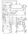
- The invention will now be described by way of example with reference to the accompanying drawing, which is a schematic diagram of a plant for producing nitrogen and argon products in accordance with the invention.
- Referring to the drawing, a feed air stream 1 is passed to a compressor 2, thereby producing an air stream 3 at an elevated pressure. The air is normally compressed to a pressure of 30-60 psig depending on the pressure at which the nitrogen product in
stream 46 is desired. If the product nitrogen is needed at a pressure higher than 50 psig, a nitrogen product compressor (not shown) may be used. Compressed air stream 3 exiting compressor 2 is cooled in an after-cooler 4 to condense some of the contained water. Carbon dioxide and remaining water in the cooled air stream 5 are removed by conventional purification means such as a molecular sieve pre-purification unit 6 containing commercially available 13X molecular sieve. In practice, two adsorbent beds are used to allow continuous operation, wherein the bed not used for purification undergoes thermal regeneration as later described. Having been depleted of carbon dioxide and water, air stream 7 enters a first heat exchanger 14, wherein the air is cooled against returning process streams to be later described. Exiting the heat exchanger 14 at a reduced temperature, thecold air stream 15 is introduced into a pressure swing adsorption unit or apparatus (PSA unit) 17 containing two or more beds of carbon molecular sieve, as more fully described later. - The
PSA unit 17 produces aPSA product stream 18 comprising a mixture of nitrogen and argon and a small amount of oxygen, typically 0.05 to 0.1%, and aPSA waste stream 16 enriched in oxygen. - The
PSA unit 17 comprises a plurality of adsorption beds each of which contains a suitable adsorbent. The adsorbent adsorbs both argon and nitrogen less readily than oxygen. Carbon molecular sieve (CMS) is the preferred adsorbent and in particular the CMS commercially available from Kuraray Chemical Company in Japan. Alternatively, carbon molecular sieve manufactured by Bergbau-Forschung in West Germany is suitable. ThePSA unit 17 operates at a temperature depending on the sieve material used, the aim being to maximise the nitrogen and argon yields while keeping oxygen to a very low level in the PSA product. For a PSA unit employing Kuraray CMS, an operational temperature range of 60°F to - 40°F is suitable, with a range of 10°F to -10°F being the preferred range for the coproduction process. At a temperature of 0°F, the Kuraray CMS was found to give a nitrogen yield of 55% and an argon yield of 70% in a product containing 0.1% O₂, as more fully described later. - The
PSA unit 17 is regenerated periodically in two steps. The pressure of each bed in turn is reduced to atmospheric pressure and then further reduced to an appropriate vacuum level using avacuum pump 11. The waste gas flows along apath including conduits path including conduits 16 and 10 and exits the plant through the conduit 13. - The PSA waste stream always flows through the first heat exchanger 14, where its refrigeration value is recovered. The atmospheric pressure portion of the PSA waste may be warmed in a heater 8 and used to regenerate the bed not undergoing adsorption in the molecular sieve pre-purification unit 6 while stream 10, the vacuum portion of the PSA waste, is drawn through the
vacuum pump 11 as discussed above. After being passed through the molecular sieve pre-purification unit 6, the heated waste stream picks up the carbon dioxide and water previously adsorbed and exits the molecular sieve pre-purification unit asstream 12. Thiswaste stream 12 and the waste stream 10 exiting thevacuum pump 11 may be combined and vented directly to atmosphere as steam 13. - The
PSA product stream 18 is passed through thePSA product receiver 19 in order to minimise flowrate fluctuations encountered during bed switch over thePSA unit 17. Exiting theproduct receiver 19, The gaseous mixture is subsequently passed to asecond heat exchanger 20, where it is cooled close to its dew point against a returningnitrogen product stream 45. The cooledstream 21 is then introduced intodistillation column 22 wherein the mixture of nitrogen, argon, and a trace amount of oxygen is separated into pure nitrogen and crude argon products. - The refrigeration for the
distillation column 22 may be provided by an external heat-pump circuit as shown by dotted lines in the drawing. A heat-pump fluid which may be a mixture of argon and nitrogen, exitscompressor 48 at an appropriate pressure as more fully described later. Compressed heat-pump fluid stream 49 is then successively cooled in first heat exchanger 14 andsecond heat exchanger 20 against the cold heat-pump fluid stream 44 returning from thethird exchanger 36. the cold high pressure heat-pump fluid stream 43 exitingexchanger 20 is divided into two parts. The first part of this stream, typically 2-10% of the total stream, entersexchanger 36 asstream 42 where it is condensed against the low pressure heat-pump fluid stream 34 and purenitrogen product stream 29 returning fromdistillation column 22. Thestream 35 leavingexchanger 36 is expanded in a Joule-Thomson (J-T)valve 37 to an appropriate pressure as discussed below. The remaining portion ofstream 43 enters aturboexpander 40 asstream 41 where it is expanded to produce acolder stream 39 exiting the turboexpander. Thestream 41 is expanded to the same pressure asstream 35 so that the pressures ofstream streams stream 30 and enterreboiler 23 at the bottom ofdistillation column 22. - In the reboiler,
stream 30 is condensed against the reboil vapors leaving the reboiler. The condensed heat-pump fluid stream 31 exitingreboiler 23 is then expanded in a Joule-Thomsonvalve 32 to yield an even colder low pressure heat-pump fluid stream 33. This latter stream is passed to acondenser 25 where it is used to condense part of the overheadnitrogen product stream 27 leaving the distillation column. The condensed overhead stream comprising essentially pure nitrogen is returned to thedistillation column 22 asreflux stream 26. - The composition and pressure of
stream 30 are chosen in such a way that it condenses against the reboil vapors inreboiler 23. In addition, the stream after being expanded in a Joule-Thomsonvalve 32 condenses an appropriate amount of overhead nitrogen product to provide the necessary reflux to thedistillation column 22. Also, an overall energy balance across the distillation column, which takes column heat in-leak into account, is satisfied. For a heat-pump fluid stream consisting of a 50:50 mixture of argon and nitrogen, the pressure ofstream 30 may be 78.0 psia for a distillation column operating at a pressure of about 45.0 psia, and the flowrate and temperature ofstream 30 may be determined by the amount of material processed in the distillation column and by the overall energy balance across the distillation column, respectively. Oncestream 30 is completely characterised, the pressure of the high pressure heat-pump fluid stream 49 may be determined by making an overall plant energy balance. - Both the low pressure heat-
pump fluid stream 34 leaving the distillationcolumn overhead condenser 25 and the uncondensed porition ofnitrogen product stream 29 are warmed inthird heat exchanger 36,second heat exchanger 20 and first heat exchanger 14, respectively, in order to recover their refrigeration. The nitrogen product stream is sent viastream 46 to storage, a nitrogen liquefaction plant, or delivered to an industrial user. The low pressure heat-pump fluid stream after being warmed up in exchangers is compressed incompressor 48 and used in the aforementioned heat-pump refrigeration circuit. In addition to the overhead pure nitrogen product stream mentioned before, thedistillation column 22 concurrently produces an aforementioned liquidcrude argon stream 24 as the bottoms product. This stream may be further purified to produce pure argon in equipment (not shown) such as a conventional DeOxo unit for removing oxygen. - This example illustrates the low temperature PSA stage used in our argon and nitrogen coproduction process. In contrast with ambient temperature PSA, relatively longer cycle times are needed for the low temperature PSA stage. Also, since the gases adsorb much more strongly at low temperature, vacuum regeneration is used for low temperature PSA. For the low temperature PSA discussed in this example, an adsorption pressure of 36.0 psig, a desorption pressure of 100 mbar, and an operating temperature of 0°F was used. A 3-bed PSA employing a mixture of aforementioned Kuraray CMS, 2mm + 40-60 mesh, was used.
- The complete cycle for this low temperature PSA is shown in Table I below. In each half of this cycle (separated by the dotted line in the Table), one of the primary beds (bed A or B) is first pressurised (step a or h) and then set to produce nitrogen product. During this time, the other primary bed undergoes regeneration by either atmospheric or vacuum venting (steps b & c or i & j). Subsequently, while the first primary bed continues to produce, the secondary bed (bed C) is regenerated through the primary bed undergoing regeneration (step d or k). For part of each half cycle, the product from the first primary bed is passed through the secondary bed (bed c) for further purification, while the other primary bed continues to be regenerated by vacuum venting (step e or l). After the end of production in each half cycle, pressure equalisation between the secondary bed and the regenerated primary bed is effected and then the pressure equalisation between the primary beds is effected.
- In comparison with ambient temperature PSA, where a total cycle time of 4 to 8 min, will normally be used, the cycle time for this low temperature PSA is 2 to 4 times longer. For the conditions discussed in this example, a nitrogen yield of 55 % and an argon yield of 70% for a product containing 0.1% oxygen was obtained.

- Typical pressure, temperature and composition of various process steam for our argon and nitrogen coproduction process are illustrated in this example and are listed in the accompanying Table II. The stream numbers correspond to the reference numerals used in the drawing. Only compositions of nitrogen, oxygen and argon in various streams are shown. Other components such as carbon dioxide and water may be present in small amounts in some of the streams. This example is for the case in which the fed air is compressed to a pressure of 49.0 psia and the low temperature PSA is operated at a temperature of 0°F. the nitrogen product leaving the distillation column is at a pressure of 44.0 psia while the crude argon product leaving the distillation column is a saturated liquid. A total of 40 theoretical distillation column trays produce nitrogen and argon products whose compositions are listed in the accompanying Table II.


- The foregoing and other various changes in form and details may be made without departing from the spirit and scope of the present invention. Consequently, it is intended that the appended claims be interpreted as including all such changes and modifications.
Claims (10)
Applications Claiming Priority (2)
| Application Number | Priority Date | Filing Date | Title |
|---|---|---|---|
| US06/914,096 US4732580A (en) | 1986-10-01 | 1986-10-01 | Argon and nitrogen coproduction process |
| US914096 | 1986-10-01 |
Publications (2)
| Publication Number | Publication Date |
|---|---|
| EP0262889A2 true EP0262889A2 (en) | 1988-04-06 |
| EP0262889A3 EP0262889A3 (en) | 1988-11-23 |
Family
ID=25433909
Family Applications (1)
| Application Number | Title | Priority Date | Filing Date |
|---|---|---|---|
| EP87308544A Withdrawn EP0262889A3 (en) | 1986-10-01 | 1987-09-28 | Argon and nitrogen coproduction process |
Country Status (6)
| Country | Link |
|---|---|
| US (1) | US4732580A (en) |
| EP (1) | EP0262889A3 (en) |
| JP (1) | JPS6391475A (en) |
| AU (1) | AU576115B2 (en) |
| CA (1) | CA1291023C (en) |
| ZA (1) | ZA876420B (en) |
Cited By (4)
| Publication number | Priority date | Publication date | Assignee | Title |
|---|---|---|---|---|
| EP0512781A1 (en) * | 1991-05-09 | 1992-11-11 | The BOC Group plc | Improvements in pressure swing adsorption plants |
| EP0520672A3 (en) * | 1991-06-24 | 1993-06-16 | The Boc Group, Inc. | Method of removing gases and light hydrocarbons from gas streams |
| FR2705141A1 (en) * | 1993-05-11 | 1994-11-18 | Air Liquide | Cryogenic method and installation for producing argon |
| EP0852325A2 (en) * | 1997-01-07 | 1998-07-08 | Praxair Technology, Inc. | Cryogenic hybrid system for producing low purity oxygen and high purity nitrogen |
Families Citing this family (17)
| Publication number | Priority date | Publication date | Assignee | Title |
|---|---|---|---|---|
| US4817392A (en) * | 1984-12-21 | 1989-04-04 | Air Products And Chemicals, Inc. | Process for the production of argon |
| GB8826378D0 (en) * | 1988-11-10 | 1988-12-14 | Wells A A | Pressure swing gas separation |
| US5125934A (en) * | 1990-09-28 | 1992-06-30 | The Boc Group, Inc. | Argon recovery from argon-oxygen-decarburization process waste gases |
| US5220797A (en) * | 1990-09-28 | 1993-06-22 | The Boc Group, Inc. | Argon recovery from argon-oxygen-decarburization process waste gases |
| US5090973A (en) * | 1990-10-23 | 1992-02-25 | The Boc Group, Inc. | Psa employing high purity purging |
| US5601634A (en) * | 1993-09-30 | 1997-02-11 | The Boc Group, Inc. | Purification of fluids by adsorption |
| US5570582A (en) * | 1994-03-10 | 1996-11-05 | The Boc Group, Inc. | Cryogenic refrigeration method for use in connection with a cryogenic temperature swing adsorption process |
| US5666828A (en) * | 1996-06-26 | 1997-09-16 | Praxair Technology, Inc. | Cryogenic hybrid system for producing low purity oxygen and high purity oxygen |
| US6351971B1 (en) * | 2000-12-29 | 2002-03-05 | Praxair Technology, Inc. | System and method for producing high purity argon |
| US6500235B2 (en) * | 2000-12-29 | 2002-12-31 | Praxair Technology, Inc. | Pressure swing adsorption process for high recovery of high purity gas |
| US7501009B2 (en) | 2006-03-10 | 2009-03-10 | Air Products And Chemicals, Inc. | Combined cryogenic distillation and PSA for argon production |
| CA2728244A1 (en) * | 2008-06-19 | 2009-12-23 | William Brigham | Hybrid air seperation method with noncryogenic preliminary enrichment and cryogenic purification based on a single component gas or liquid generator |
| MX354355B (en) * | 2008-08-15 | 2018-02-22 | Watherford Tech Holdings Llc | Multiphase drilling systems and methods. |
| US10059613B1 (en) * | 2012-07-23 | 2018-08-28 | Peter F. Santina | Removal of contaminants from water |
| US9925514B2 (en) | 2016-02-22 | 2018-03-27 | Air Products And Chemicals, Inc. | Modified chabazite adsorbent compositions, methods of making and using them |
| US9708188B1 (en) * | 2016-02-22 | 2017-07-18 | Air Products And Chemicals, Inc. | Method for argon production via cold pressure swing adsorption |
| GB201818896D0 (en) * | 2018-11-20 | 2019-01-02 | Gas Recovery And Recycle Ltd | Gas recovery method |
Citations (4)
| Publication number | Priority date | Publication date | Assignee | Title |
|---|---|---|---|---|
| US4256469A (en) * | 1978-11-06 | 1981-03-17 | Linde Aktiengesellschaft | Repressurization technique for pressure swing adsorption |
| US4477265A (en) * | 1982-08-05 | 1984-10-16 | Air Products And Chemicals, Inc. | Argon purification |
| GB2170894A (en) * | 1985-01-14 | 1986-08-13 | Boc Group Plc | Separation of a gas mixture |
| GB2171927A (en) * | 1985-03-04 | 1986-09-10 | Boc Group Plc | Method and apparatus for separating a gaseous mixture |
Family Cites Families (23)
| Publication number | Priority date | Publication date | Assignee | Title |
|---|---|---|---|---|
| GB809168A (en) * | 1956-08-29 | 1959-02-18 | British Oxygen Co Ltd | Purification of argon |
| GB927518A (en) * | 1959-11-23 | 1963-05-29 | British Oxygen Co Ltd | Process for the separation of krypton and xenon from mixture with oxygen |
| US3173778A (en) * | 1961-01-05 | 1965-03-16 | Air Prod & Chem | Separation of gaseous mixtures including argon |
| GB1446201A (en) * | 1973-01-08 | 1976-08-18 | Air Prod & Chem | Purification of inert gases |
| NL7311471A (en) * | 1973-08-21 | 1975-02-25 | Philips Nv | DEVICE FOR LIQUIDIZATION OF VERY LOW TEMPERATURE CONDENSING GASES. |
| SU516410A1 (en) * | 1973-12-06 | 1976-06-05 | Ленинградский технологический институт холодильной промышленности | Argon cleaning method |
| US3967464A (en) * | 1974-07-22 | 1976-07-06 | Air Products And Chemicals, Inc. | Air separation process and system utilizing pressure-swing driers |
| JPS5326276A (en) * | 1976-08-25 | 1978-03-10 | Hitachi Ltd | Liquefying separation method of air |
| US4144038A (en) * | 1976-12-20 | 1979-03-13 | Boc Limited | Gas separation |
| JPS5930646B2 (en) * | 1977-10-24 | 1984-07-28 | 株式会社ほくさん | Argon gas purification method |
| GB1572968A (en) * | 1978-05-31 | 1980-08-06 | Air Prod & Chem | Method of purifying crude argon |
| JPS56168833A (en) * | 1980-06-02 | 1981-12-25 | Mitsubishi Heavy Ind Ltd | Oxygen absorbent from two-component gas of oxygen and nitrogen and its using method |
| GB2080929B (en) * | 1980-07-22 | 1984-02-08 | Air Prod & Chem | Producing gaseous oxygen |
| US4433990A (en) * | 1981-12-08 | 1984-02-28 | Union Carbide Corporation | Process to recover argon from oxygen-only air separation plant |
| US4439213A (en) * | 1981-12-30 | 1984-03-27 | The C. M. Kemp Manufacturing Co. | Nitrogen generation system |
| JPS58140309A (en) * | 1982-02-17 | 1983-08-20 | Hitachi Ltd | Method for enriching nitrogen in air |
| JPS58167411A (en) * | 1982-03-25 | 1983-10-03 | Nippon Sanso Kk | Preparation of argon |
| JPS598605A (en) * | 1982-07-07 | 1984-01-17 | Osaka Oxgen Ind Ltd | Concentration of nitrogen |
| US4421531A (en) * | 1982-09-13 | 1983-12-20 | Air Products And Chemicals, Inc. | Adiabatic pressure swing absorption process for removing low concentrations of oxygen from mixed gas streams |
| US4421530A (en) * | 1982-09-13 | 1983-12-20 | Air Products And Chemicals, Inc. | Process for removing oxygen from mixed gas streams using a swing adiabatic absorption-isothermal desorption cycle |
| JPS5992907A (en) * | 1982-11-19 | 1984-05-29 | Seitetsu Kagaku Co Ltd | Preparation of concentrated argon |
| JPS6027607A (en) * | 1983-07-21 | 1985-02-12 | Nippon Sanso Kk | Preparation of nitrogen by pressure swing adsorption method |
| JPS6138384A (en) * | 1984-07-31 | 1986-02-24 | 宇野 煕 | Method of recovering argon gas for atmosphere |
-
1986
- 1986-10-01 US US06/914,096 patent/US4732580A/en not_active Expired - Lifetime
-
1987
- 1987-08-27 ZA ZA876420A patent/ZA876420B/en unknown
- 1987-09-28 EP EP87308544A patent/EP0262889A3/en not_active Withdrawn
- 1987-09-28 CA CA000548023A patent/CA1291023C/en not_active Expired - Lifetime
- 1987-09-30 AU AU79220/87A patent/AU576115B2/en not_active Ceased
- 1987-10-01 JP JP62249073A patent/JPS6391475A/en active Granted
Patent Citations (4)
| Publication number | Priority date | Publication date | Assignee | Title |
|---|---|---|---|---|
| US4256469A (en) * | 1978-11-06 | 1981-03-17 | Linde Aktiengesellschaft | Repressurization technique for pressure swing adsorption |
| US4477265A (en) * | 1982-08-05 | 1984-10-16 | Air Products And Chemicals, Inc. | Argon purification |
| GB2170894A (en) * | 1985-01-14 | 1986-08-13 | Boc Group Plc | Separation of a gas mixture |
| GB2171927A (en) * | 1985-03-04 | 1986-09-10 | Boc Group Plc | Method and apparatus for separating a gaseous mixture |
Cited By (5)
| Publication number | Priority date | Publication date | Assignee | Title |
|---|---|---|---|---|
| EP0512781A1 (en) * | 1991-05-09 | 1992-11-11 | The BOC Group plc | Improvements in pressure swing adsorption plants |
| EP0520672A3 (en) * | 1991-06-24 | 1993-06-16 | The Boc Group, Inc. | Method of removing gases and light hydrocarbons from gas streams |
| FR2705141A1 (en) * | 1993-05-11 | 1994-11-18 | Air Liquide | Cryogenic method and installation for producing argon |
| EP0852325A2 (en) * | 1997-01-07 | 1998-07-08 | Praxair Technology, Inc. | Cryogenic hybrid system for producing low purity oxygen and high purity nitrogen |
| EP0852325A3 (en) * | 1997-01-07 | 1998-12-16 | Praxair Technology, Inc. | Cryogenic hybrid system for producing low purity oxygen and high purity nitrogen |
Also Published As
| Publication number | Publication date |
|---|---|
| US4732580A (en) | 1988-03-22 |
| ZA876420B (en) | 1988-03-09 |
| AU576115B2 (en) | 1988-08-11 |
| JPS6391475A (en) | 1988-04-22 |
| AU7922087A (en) | 1988-04-14 |
| EP0262889A3 (en) | 1988-11-23 |
| JPH0310868B2 (en) | 1991-02-14 |
| CA1291023C (en) | 1991-10-22 |
Similar Documents
| Publication | Publication Date | Title |
|---|---|---|
| EP0262889A2 (en) | Argon and nitrogen coproduction process | |
| US5125934A (en) | Argon recovery from argon-oxygen-decarburization process waste gases | |
| EP3784963B1 (en) | System and method for enhanced recovery of argon and oxygen from a nitrogen producing cryogenic air separation unit | |
| EP0744205B1 (en) | Integrated air separation method | |
| US5220797A (en) | Argon recovery from argon-oxygen-decarburization process waste gases | |
| EP0234895B1 (en) | Recovery of argon | |
| EP3784966B1 (en) | System and method for high recovery of nitrogen and argon from a moderate pressure cryogenic air separation unit | |
| CA3097150C (en) | System and method for enhanced recovery of argon and oxygen from a nitrogen producing cryogenic air separation unit | |
| EP0384688B2 (en) | Air separation | |
| US4861361A (en) | Argon and nitrogen coproduction process | |
| KR102258573B1 (en) | Systems and methods for improved recovery of argon and oxygen from nitrogen generating cryogenic air separation units | |
| EP3208563A1 (en) | Method for argon production via cold pressure swing adsorption | |
| US5049174A (en) | Hybrid membrane - cryogenic generation of argon concurrently with nitrogen | |
| US5100446A (en) | Crude neon production system | |
| US6351971B1 (en) | System and method for producing high purity argon | |
| US5463869A (en) | Integrated adsorption/cryogenic distillation process for the separation of an air feed | |
| US5701763A (en) | Cryogenic hybrid system for producing low purity oxygen and high purity nitrogen | |
| CN107850386B (en) | Method and apparatus for argon recovery in a cryogenic air separation unit integrated with a pressure swing adsorption system | |
| GB2170894A (en) | Separation of a gas mixture | |
| GB2181528A (en) | Air separation | |
| EP0714005A2 (en) | Air separation | |
| CA2068171A1 (en) | Production of the molecular sieve regeneration stream from the high pressure column to reduce the feed air pressure in air separation plants |
Legal Events
| Date | Code | Title | Description |
|---|---|---|---|
| PUAI | Public reference made under article 153(3) epc to a published international application that has entered the european phase |
Free format text: ORIGINAL CODE: 0009012 |
|
| AK | Designated contracting states |
Kind code of ref document: A2 Designated state(s): DE ES FR GB IT NL |
|
| PUAL | Search report despatched |
Free format text: ORIGINAL CODE: 0009013 |
|
| AK | Designated contracting states |
Kind code of ref document: A3 Designated state(s): DE ES FR GB IT NL |
|
| 17P | Request for examination filed |
Effective date: 19890707 |
|
| 17Q | First examination report despatched |
Effective date: 19900117 |
|
| STAA | Information on the status of an ep patent application or granted ep patent |
Free format text: STATUS: THE APPLICATION IS DEEMED TO BE WITHDRAWN |
|
| 18D | Application deemed to be withdrawn |
Effective date: 19900728 |
|
| RIN1 | Information on inventor provided before grant (corrected) |
Inventor name: MACLEAN, DONALD L. Inventor name: JAIN, RAVI Inventor name: LERNER, STEVEN L. Inventor name: MOSTELLO, ROBERT A. |