EP0262614A1 - Automatic compensation for image-intensifier tube distortion - Google Patents
Automatic compensation for image-intensifier tube distortion Download PDFInfo
- Publication number
- EP0262614A1 EP0262614A1 EP87114051A EP87114051A EP0262614A1 EP 0262614 A1 EP0262614 A1 EP 0262614A1 EP 87114051 A EP87114051 A EP 87114051A EP 87114051 A EP87114051 A EP 87114051A EP 0262614 A1 EP0262614 A1 EP 0262614A1
- Authority
- EP
- European Patent Office
- Prior art keywords
- magnetic field
- earth
- compensating
- angle
- image intensifier
- Prior art date
- Legal status (The legal status is an assumption and is not a legal conclusion. Google has not performed a legal analysis and makes no representation as to the accuracy of the status listed.)
- Withdrawn
Links
Images


Classifications
-
- H—ELECTRICITY
- H01—ELECTRIC ELEMENTS
- H01J—ELECTRIC DISCHARGE TUBES OR DISCHARGE LAMPS
- H01J29/00—Details of cathode-ray tubes or of electron-beam tubes of the types covered by group H01J31/00
- H01J29/003—Arrangements for eliminating unwanted electromagnetic effects, e.g. demagnetisation arrangements, shielding coils
-
- H—ELECTRICITY
- H01—ELECTRIC ELEMENTS
- H01J—ELECTRIC DISCHARGE TUBES OR DISCHARGE LAMPS
- H01J2229/00—Details of cathode ray tubes or electron beam tubes
- H01J2229/0007—Elimination of unwanted or stray electromagnetic effects
- H01J2229/003—Preventing or cancelling fields entering the enclosure
-
- H—ELECTRICITY
- H01—ELECTRIC ELEMENTS
- H01J—ELECTRIC DISCHARGE TUBES OR DISCHARGE LAMPS
- H01J2231/00—Cathode ray tubes or electron beam tubes
- H01J2231/50—Imaging and conversion tubes
- H01J2231/50005—Imaging and conversion tubes characterised by form of illumination
- H01J2231/5001—Photons
- H01J2231/50031—High energy photons
- H01J2231/50036—X-rays
-
- H—ELECTRICITY
- H01—ELECTRIC ELEMENTS
- H01J—ELECTRIC DISCHARGE TUBES OR DISCHARGE LAMPS
- H01J2231/00—Cathode ray tubes or electron beam tubes
- H01J2231/50—Imaging and conversion tubes
- H01J2231/50057—Imaging and conversion tubes characterised by form of output stage
- H01J2231/50063—Optical
Definitions
- the present invention relates to imaging devices and, more particularly to techniques for eliminating image tube distortion arising from interaction of moving charged particles with extraneous magnetic fields.
- An X-ray image intensifier employs a large photocathode responsive to impinging X radiation to emit a pattern of electrons which are accelerated toward a smaller anode upon which they impact at high velocity.
- the impacting electrons generate a corresponding pattern of light representing the output of the image intensifier.
- the electrons are changed particles, they are subject to electrostatic and magnetic fields.
- the presence of an electrostatic field between cathode and anode produces the desired energy gain.
- an electronic lens, built into the imaging tube produces fields effective for focusing the electrons.
- External magnetic fields are preferably excluded or compensated to prevent distortion of the output pattern.
- Sides of an imaging tube are conventionally shielded with a material of high magnetic permeability such as, for example, Mu metal. Shielding the cathode or anode ends of the imaging tube is infeasible since this interferes with the necessary X-ray input and light output.
- external magnetic fields in the environment of the equipment are capable of entering the image-intensifier tube and disturbing the desired paths of the electrons. As a result, the output image is distorted.
- the distortion is proportional to the magnetic field strength of the interfering magnetic field times the sine of the angle between the direction of the magnetic field and the path of the electrons.
- the principal interfering magnetic field is that of the earth.
- the earth's magnetic field is constant in amplitude and direction.
- a compensating magnetic field having the required amplitude and direction to cancel the effect of the earth's magnetic field.
- One method may achieve partial or complete cancellation using one or more permanent magnets appropriately placed in the vicinity of the image intensifier tube.
- a more flexible technique employs a compensating element built into, or applied to, an image intensifier tube and receiving a control voltage capable of generating a compensating field in the tube effective for reducing or eliminating the effects of the earth's magnetic field on the paths of the electrons.
- the above compensation techniques are effective for compensating magnetic field effects in a satisfactory image intensifier tube.
- Modern fluoroscopic systems permit the patient to remain stationary while rotating the X-ray source and image intensifier tube, as necessary, to achieve a desired view of the patient.
- the angle between the earth's magnetic field and the paths of the electrons in the image intensifier tube is not stationary but may assume any arbitrary value.
- the static compensation techniques of the prior art not only do not work but, in fact, it is possible to achieve angular relationships between compensating field and electro n travel wherein the compensating field may add to the distortion rather than reduce it.
- Such ferromagnetic objects may distort the earth's magnetic field so that compensation for the earth's magnetic field, based on the assumption that its magnitude and direction are constant over all possible positions of the fluoroscopic X-ray imaging system, produces substantial error.
- more than one fluoroscopic X-ray imaging system may be independently positionable about a patient.
- Each of the systems may contain ferromagnetic material capable of distorting the magnetic field influencing the other system. Since they are independently positionable, the resulting influences depend on the positional relationships of each of the systems with respect to the earth's magnetic field, and with respect to each other.
- a second, independently positionable fluoroscopic X-ray imaging system may vary its magnetic influence depending on whether it is turned on or off. The same is true of other equipment in the vicinity of the imaging system, whether or not movable. For example, applying power to any nearby equipment having the ability to produce a magnetic field in the vicinity of the imaging system, may produce a resultant magnetic field varying significantly from that of the earth's magnetic field alone.
- the present invention provides a dynamic compensating system for an image intensifier tube employing a compensating element in vicinity of the image intensifier tube for applying a compensating field to cancel the effect of the earth's magnetic field and optionally other perturbing magnetic influences.
- a source of compensating current is responsive to the cosine of the angle between the tube axis and the perturbing magnetic field vector for varying an amplitude of the compensating current.
- Means are provided for compensating for local perturbations and sources of magnetic field having varying strengths and angles within the range of motion of the image intensifier.
- apparatus for dynamic compensation of distortion in an image intensifier tube comprising: the tube including an input face and an output face, the input face and output face defining an axis of the tube, a compensating element in the tube, means for applying a compensating signal to the compensating element, and means for varying the compensating signal in relationship to an angle between a perturbing magnetic field and the axis.
- FIG. 1 there is shown, generally at 10, a highly schematic representation of an X-ray fluoroscopic imaging system.
- An X-ray source 12 directs a beam of X rays represented by a tube center line 14 toward an image intensifier tube 16.
- a patient 18, or other object may be supported by conventional means in a position intercepting the beam of X rays in its travel from X-ray source 12 to image intensifier tube 16. Any desired angular relationship may be obtained between center line 14 and patient 18 using conventional rotating support apparatus (not shown), as indicated by dashed circles 20 and 22.
- An earth's magnetic field vector B 24, illustrated in conventional vector notation, has a magnitude varying slightly from place to place on the earth's surface.
- An angle between earth's magnetic field vector B 24 and a horizontal plane varies greatly over the earth's surface. Both magnitude and direction of earth's magnetic field vector B 24 are influenced by local perturbing objects such as, for example, a mass of ferromagnetic material 26 in the vicinity of X-ray fluoroscopic imaging system 10.
- Mass of ferromagnetic material 26 may be capable of distorting earth's magnetic field vector B 24 over a short range, whereby distortion of the output image varies with the distance between image intensifier tube 16 and mass of ferromagnetic material 26, with the angle between center line 14 and an axis 28 of mass of ferromagnetic material 26, and with the angle between earth's magnetic field vector B 24 and axis 28.
- mass of ferromagnetic material 26 may contain elements (not shown) varying in magnetic field depending on whether such elements are turned on or off.
- image intensifier tube 16 includes an envelope 30 having an input face 32, an output face 34 and a wall 36 fully enclosing internal components.
- a scintillation layer 40 within input face 32 includes a phosphor effective for producing a pattern of light corresponding to a pattern of incident X rays.
- a photocathode layer 42 closely coupled to scintillation layer 40, produces a pattern of electrons corresponding to a pattern of light generated by scintillation layer 40.
- Photocathode layer 42 is conventionally maintained at a negative reference voltage such as, for example, a ground potential.
- a focus electrode 44 near output face 34 is maintained at a positive potential of, for example, about 30 kilovolts, for accelerating electrons liberated from photocathode layer 42 toward an output fluorescent screen 46.
- One or more additional focus electrodes 48 and 50 together with external conventional control circuits, form an electronic lens for directing electrons emitted from photocathode layer 42 along controlled paths, indicated by paths 54, 56 and 58, whereby an output image is formed on output fluorescent screen 46 corresponding to the pattern of electrons emitted by photocathode layer 42.
- Such pattern of electrons being, in turn, related to the pattern of X rays impinging on scintillation layer 40, thus produces an output image on output fluorescent screen 46 representing a minified image of an attenuation pattern to which the X rays are exposed.
- the accelerat ion applied to the electrons by the accelerating field of focus electrode 44 increases their energy, whereby a greater number of photons of light are emitted by output fluorescent screen 46 than are generated by impingement of the X rays on scintillation layer 40. In this manner, the image is brightened or intensified.
- Output fluorescent screen 46 and output face 34 are transparent to permit viewing, or other use, of the intensified image external to image intensifier tube 16.
- a magnetic shielding layer 60 is disposed on wall 36 to prevent distortion of the output image by earth's magnetic field vector B 24. It is not feasible to extend magnetic shielding layer 60 to cover input face 32 and output face 34 since this would interfere with the required entry of X rays and the exit of the output image. Thus, for some angular relationships between center line 14 and earth's magnetic field vector B 24, the paths of electrons travelling along paths 54, 56 and 58 may be perturbed by the entry of earth's magnetic field vector B 24 through the unshielded openings at input face 32 and 34.
- FIG. 3 a worst-case situation is shown in which earth's magnetic field vector B 24 is aligned with center line 14. In this orientation, earth's magnetic field vector B 24 has greatest access to unshielded input face 32 and output face 34.
- the amount by which an electron path is disturbed by earth's magnetic field vector B 24 is proportional to the magnitude of earth's magnetic field vector B 24 times the sine of the angle between them.
- the angle between earth's magnetic field vector B 24 and path 56 being zero, the disturbance of path 56 is also zero.
- An electron velocity vector 62 along path 54 or 58 makes an angle a with respect to the angle of earth's magnetic field vector B 24.
- paths 54 and 58 are perturbed by earth's magnetic field vector B 24, whereby an output image formed on output fluorescent screen 46 is distorted.
- the output image also consists of a straight line 64.
- central path 56 remains unperturbed since the angle between it and earth's magnetic field vector B 24 is zero.
- Paths 54 and 58 are at angles a and -a with respect to the angle of earth's magnetic field vector B 24 and thus the sine of these angle is not zero.
- straight line 64 is distorted in opposite directions on opposed sides of a center 68 into a S-shaped curve 66 as shown in Fig. 5.
- S-shaped curve 66 does not follow the above directive that portions of straight line 64 further from a center 68 should experience increasing distortion.
- the fields produced by focus electrode 48 and 50 (Fig. 3) near wall 36 tends to overcome the perturbation of electrons on paths terminating nearest the edges of output fluorescent screen 46.
- a compensating coil 70 receives a compensating current having an amplitude effective for compensating for the influence of earth's magnetic field vector B 24 on paths 54 and 58 (as we ll as intermediate paths not illustrated) and thus for eliminating distortion in the output image.
- compensating coil 70 is illustrated within envelope 30, in alternative embodiments, compensating coil 70 may be disposed external to envelope 30 in the vicinity of input face 32.
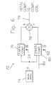
- a compensation current generator 72 includes a conventional angle-measurement device 74 for measuring an angle a described by center line 14 (Fig. 2) with respect to any suitable coordinate system.
- the measured angle a is applied to an earth compensator 76 which also receives information about the amplitude and angle of earth's magnetic field vector B 24.
- Earth compensator 76 generates a signal proportional to the cosine of the angle between earth's magnetic field vector B 24 and center line 14 for application to an adder 78. If only the influence of earth's magnetic field vector B 24 is being compensated, the output of earth compensator 76 may bypass adder 78 and be applied on a line 79 directly to compensating coil 70.
- Compensation current generator 72 also contains a compensator 80 to compensate for one or more other perturbing magnetic fields which may have different amplitudes and directions than earth's magnetic field vector B 24 such as, for example, the influence of perturbing magnetic field O 82 (Fig. 1) acting along axis 28.
- other magnetic field O 82 may vary in both amplitude and angle from place to place within the range of movement of image intensifier tube 16.
- the magnitude, angle or even the existence, of perturbing magnetic field O 82 may depend on external factors such as, for example, whether external equipment is turned on, or the mode of operation of such external equipment.
- additional parameters of perturbing magnetic field O 82 may be required for application to compensator 80 on a line 84.
- the source of such additional data may be empirical from continuing measurement, or one-time measurement yielding stored results which are then called upon for providing required values as needed.
- the functions of earth compensator 76 and compensator 80 may be performed from stored values given a measured value of angle a .
- the stored value may be in the form of one or more equations whose value is determined from an existing value of angle a .
- a lookup table (not shown) of values of compensating current for application on line 79 may be related to values of a . Upon measurement of a value of a , access is made to the lookup table to determine the corresponding value of the compensating current.
- Either equations or lookup table may accommodate variations in perturbing magnetic field O 82, either due to short-range effects or to differences between an external equipment being on or off.
- the constants and variables in the equations or the values in the lookup table relating to perturbing magnetic field O 82 may be measured one time and stored for continuous subsequent use.
Landscapes
- Physics & Mathematics (AREA)
- Electromagnetism (AREA)
- Image-Pickup Tubes, Image-Amplification Tubes, And Storage Tubes (AREA)
Applications Claiming Priority (2)
| Application Number | Priority Date | Filing Date | Title |
|---|---|---|---|
| US91492986A | 1986-10-03 | 1986-10-03 | |
| US914929 | 1986-10-03 |
Publications (1)
| Publication Number | Publication Date |
|---|---|
| EP0262614A1 true EP0262614A1 (en) | 1988-04-06 |
Family
ID=25434979
Family Applications (1)
| Application Number | Title | Priority Date | Filing Date |
|---|---|---|---|
| EP87114051A Withdrawn EP0262614A1 (en) | 1986-10-03 | 1987-09-25 | Automatic compensation for image-intensifier tube distortion |
Country Status (3)
| Country | Link |
|---|---|
| EP (1) | EP0262614A1 (cg-RX-API-DMAC7.html) |
| JP (1) | JPS63121239A (cg-RX-API-DMAC7.html) |
| IL (1) | IL83527A0 (cg-RX-API-DMAC7.html) |
Cited By (2)
| Publication number | Priority date | Publication date | Assignee | Title |
|---|---|---|---|---|
| EP0657913A1 (en) * | 1993-12-10 | 1995-06-14 | Sony Corporation | Cathode ray tube comprising terrestrial magnetism sensors |
| WO2014031208A3 (en) * | 2012-05-30 | 2014-07-17 | Hvm Technology, Inc. | Shock-resistant image intensifier |
Citations (3)
| Publication number | Priority date | Publication date | Assignee | Title |
|---|---|---|---|---|
| DE2811373A1 (de) * | 1977-03-28 | 1978-10-05 | Philips Nv | Bildverstaerkerroehre |
| GB1574226A (en) * | 1976-06-14 | 1980-09-03 | Styner & Bienz Ag | Method of producing a cover for a tin having a weakening scoring for tearing it open apparatus for carrying out this method and a cover produced in accordance with such method |
| US4523091A (en) * | 1982-03-22 | 1985-06-11 | Siemens Gammasonics, Inc. | Radiation detecting apparatus with reduced magnetic field sensitivity |
-
1987
- 1987-08-13 IL IL83527A patent/IL83527A0/xx unknown
- 1987-09-25 EP EP87114051A patent/EP0262614A1/en not_active Withdrawn
- 1987-10-02 JP JP62248193A patent/JPS63121239A/ja active Granted
Patent Citations (3)
| Publication number | Priority date | Publication date | Assignee | Title |
|---|---|---|---|---|
| GB1574226A (en) * | 1976-06-14 | 1980-09-03 | Styner & Bienz Ag | Method of producing a cover for a tin having a weakening scoring for tearing it open apparatus for carrying out this method and a cover produced in accordance with such method |
| DE2811373A1 (de) * | 1977-03-28 | 1978-10-05 | Philips Nv | Bildverstaerkerroehre |
| US4523091A (en) * | 1982-03-22 | 1985-06-11 | Siemens Gammasonics, Inc. | Radiation detecting apparatus with reduced magnetic field sensitivity |
Non-Patent Citations (1)
| Title |
|---|
| PATENT ABSTRACTS OF JAPAN, E Section, Vol. 4, No. 157, November 4, 1980 The Patent Office Japanese Government page 128 E 32 * Kokai-No. 55-108 147 (Tokyo Shibaura Denki) * * |
Cited By (4)
| Publication number | Priority date | Publication date | Assignee | Title |
|---|---|---|---|---|
| EP0657913A1 (en) * | 1993-12-10 | 1995-06-14 | Sony Corporation | Cathode ray tube comprising terrestrial magnetism sensors |
| US5614791A (en) * | 1993-12-10 | 1997-03-25 | Sony Corporation | Cathode ray tube |
| WO2014031208A3 (en) * | 2012-05-30 | 2014-07-17 | Hvm Technology, Inc. | Shock-resistant image intensifier |
| US9136085B2 (en) | 2012-05-30 | 2015-09-15 | Hvm Technology, Inc. | Shock-resistant image intensifier |
Also Published As
| Publication number | Publication date |
|---|---|
| IL83527A0 (en) | 1988-01-31 |
| JPS63121239A (ja) | 1988-05-25 |
| JPH0415576B2 (cg-RX-API-DMAC7.html) | 1992-03-18 |
Similar Documents
| Publication | Publication Date | Title |
|---|---|---|
| US6976953B1 (en) | Maintaining the alignment of electric and magnetic fields in an x-ray tube operated in a magnetic field | |
| US4426721A (en) | X-ray intensifier detector system for x-ray electronic radiography | |
| CA2071883A1 (en) | Multipath laminography system | |
| US4714833A (en) | Arrangement for detecting secondary and/or backscatter electrons in an electron beam apparatus | |
| EP0142541B1 (en) | Cathode ray tube display device | |
| US6810110B2 (en) | X-ray tube for operating in a magnetic field | |
| EP0389952A2 (en) | A photoelectron microscope | |
| US4922097A (en) | Potential measurement device | |
| US5051599A (en) | Device for recognizing the impact site of a charge carrier beam on a target | |
| EP0262614A1 (en) | Automatic compensation for image-intensifier tube distortion | |
| GB1246152A (en) | Magnetic deflection apparatus | |
| US4328418A (en) | Magnetic field correction method and apparatus | |
| US4864192A (en) | CRT magnetic field compensation | |
| KR890005568A (ko) | 하전비임과 노광시스템상의 와전류효과 보상방법 | |
| US4031391A (en) | Electron microscope including improved means for determining and correcting image drift | |
| US4152599A (en) | Method for positioning a workpiece relative to a scanning field or a mask in a charged-particle beam apparatus | |
| JPH0961385A (ja) | オージェ電子分光装置 | |
| EP0340861A1 (en) | Auger spectrometry | |
| US3628009A (en) | Scanning-type sputtering mass spectrometer | |
| US5432355A (en) | Method for representing the spatial distribution of radioactive elements by means of a screen of the erasable phosphor type, and corresponding device | |
| RU2228561C2 (ru) | Времяанализирующий электронно-оптический преобразователь изображения | |
| US3767927A (en) | Electron beam apparatus with beam-stabilization system | |
| US3551671A (en) | Ion-electron image converter for use with ion microanalyzers | |
| JP3216355B2 (ja) | イメージインテンシファイア装置 | |
| US2986634A (en) | Method of examining the quality of electron-optical images and devices for carrying out this method |
Legal Events
| Date | Code | Title | Description |
|---|---|---|---|
| PUAI | Public reference made under article 153(3) epc to a published international application that has entered the european phase |
Free format text: ORIGINAL CODE: 0009012 |
|
| AK | Designated contracting states |
Kind code of ref document: A1 Designated state(s): DE FR GB NL |
|
| STAA | Information on the status of an ep patent application or granted ep patent |
Free format text: STATUS: THE APPLICATION IS DEEMED TO BE WITHDRAWN |
|
| 18D | Application deemed to be withdrawn |
Effective date: 19881007 |
|
| RIN1 | Information on inventor provided before grant (corrected) |
Inventor name: BELANGER, BARRY FREDRIC Inventor name: RELIHAN, GARY FRANCIS Inventor name: PUTRA, TIMOTHY PETER |