EP0262071A1 - Helicopter blade airfoil - Google Patents
Helicopter blade airfoil Download PDFInfo
- Publication number
- EP0262071A1 EP0262071A1 EP87630148A EP87630148A EP0262071A1 EP 0262071 A1 EP0262071 A1 EP 0262071A1 EP 87630148 A EP87630148 A EP 87630148A EP 87630148 A EP87630148 A EP 87630148A EP 0262071 A1 EP0262071 A1 EP 0262071A1
- Authority
- EP
- European Patent Office
- Prior art keywords
- airfoil
- blade
- section
- lift
- leading
- Prior art date
- Legal status (The legal status is an assumption and is not a legal conclusion. Google has not performed a legal analysis and makes no representation as to the accuracy of the status listed.)
- Granted
Links
Images


Classifications
-
- B—PERFORMING OPERATIONS; TRANSPORTING
- B64—AIRCRAFT; AVIATION; COSMONAUTICS
- B64C—AEROPLANES; HELICOPTERS
- B64C27/00—Rotorcraft; Rotors peculiar thereto
- B64C27/32—Rotors
- B64C27/46—Blades
- B64C27/467—Aerodynamic features
Definitions
- the present invention relates to a blade for a helicopter, and more particularly, to the airfoil cross section thereof.
- Rotorcraft such as helicopters
- Rotorcraft are supported vertically by a plurality of driven blades which rotate about a vertical axis. It will be appreciated that, since both the lift and propulsive force of the helicopter are supplied primarily through the large rotating blade system, it is advantageous to provide a main blade configuration which achieves a high lifting force at a given airspeed and which does not experience a high aerodynamic drag.
- the Balch airfoil designated SC1095, provides an airfoil cross section which achieves both higher maximum lift and lower zero lift aerodynamic drag at high velocity conditions as compared to the then-existing airfoils. These improvements were realized by selectively shaping the airfoil surface for both higher lift and lower drag by delaying separation of the airflow boundary layer over the airfoil, as well as decreasing the local Mach number at high freestream velocities.
- the de Simone airfoil also referred to as the SC1095-R8 configuration, is characterized in the referenced patent as an improvement over the SC1095 airfoil wherein the airfoil upper surface is shaped to distribute the surface static pressure peak over a greater area thereby reducing the likelihood of airfoil boundary layer separation.
- the SC1095-R8 airfoil achieves higher maximum lift than the SC1095 configuration at lower velocities, but is subject to higher zero lift drag forces at high velocity conditions.
- the Flemming, Jr. configuration is an improvement over the SC1095-R8 design and is particularly well adapted for use in high speed applications, such as in the radially outer tip portion of the main blade.
- the Flemming, Jr. airfoil also termed the SSC-Axx family, further reduces the zero lift drag force at high air speeds by delaying the creation of shock waves in the local airflow. This further reduction in aerodynamic drag at high air speed is achieved at the expense of some maximum lift at lower velocity operation.
- the present invention provides an improved airfoil cross section for use in a rotating helicopter blade or the like and which experiences reduced zero lift aerodynamic drag as compared to prior art airfoil configurations without incurring a penalty in the form of reduced maximum lift. Improved performance is accomplished by altering the leading edge and surface geometry of a prior art, low drag airfoil configuration to increase the maximum lift coefficient without significantly changing the drag coefficient or pitching moment about the quarter chord point.
- the forward portion of a prior art SSC-Axx family blade airfoil is thickened and "drooped" slightly, improving the blade lift coefficient.
- the result is a high lift, low drag airfoil design which obtains the best advantages of prior art designs with a single configuration.
- the performance of the airfoil section according to the present invention over the range of operating conditions is such that the same family of airfoil shapes may be used along nearly the entire helicopter rotor blade span, preferably in that portion of the span extending from the rotor hub to 90% of the span distance between the hub and the blade tip.
- a rotorcraft equipped with a rotor blade having an airfoil cross section according to the present invention requires less power to drive the main rotor, especially during periods of high speed horizontal flight in which the advancing rotor blades are subject to high relative velocity airflows.
- blades utilizing airfoils according to the present invention are subject to less torsional stress along the blade span thereby exhibiting less twisting between the hub and tip sections.
- FIG 1 shows a schematic of a helicopter rotor 10 which consists of a plurality of equally spaced blades 12 mounted for rotation with a rotor hub 14 about an axis of rotation 16.
- Each blade 12 is preferably identical to the single blade illustrated in Figure 1 and includes a root portion 18 which connects to the hub 14, a tip portion 20 which is that part of the blade farthest from the axis of rotation 16 and which therefore travels at the highest speed, and a center portion 22 extending between the hub 14 and tip 20.
- Each of the blades 12 has a leading edge 24, a trailing edge 26 and defines a chord dimension C and a span dimension S as shown in Figure 1.
- the blade 12 is an airfoil in cross section and generates lift during rotation of the blade 12.
- FIG 2 a cross section 28 of the airfoil according to the present invention is shown overlain with a cross section 30 of a prior art SSC-A10 airfoil.
- the airfoil according to the present invention also termed “SC2110" is shown with the leading edge 24 and trailing edge 26 defining a chordal distance C therebetween.
- Figure 2 also shows the airfoil chord line 30 connecting the leading and trailing edges 24, 26.
- the airfoil section 28 includes an upper surface 34 and a lower surface 36 disposed on opposite sides of the chord line 32.
- the SC2110 airfoil cross section 28 is defined in Table I which contains a listing of the vertical displacement Y u , Y1 of the airfoil upper and lower surfaces 34, 36 as a fraction of the airfoil chordal dimension C.
- the horizontal displacement of each station is represented by the column titled X/C and represents the proportional displacement along the airfoil chord line 32 from the leading edge 24 to the trailing edge 26.
- the SC2110 airfoil is a member of a corresponding family of similar shapes of differing thicknesses as defined by the ratio of airfoil maximum thickness (t max ) to airfoil chord (C).
- the airfoil designations SSC-A10 and SC2110 thus each represent individual members of the respective airfoil families SSC-Axx and SC21xx wherein the ratio of t max to C is approximately 0.10, or 10%.
- the SC21xx family of airfoils is defined by Table II wherein the vertical displacement of the upper and lower airfoil surfaces is tabulated at a plurality of stations along the airfoil chord 32, each station defined as in Table I as a proportional displacement X/C of the distance between the blade leading and trailing edges 24, 26. Vertical displacements are expressed as a ratio of the vertical displacement Y u , Y1, to the blade maximum thickness, t max .
- the airfoil section 28 is a derivative of the SSC-A10 cross section 30 and differs therefrom both in configuration and in performance.
- the SC2110 cross section 28 is significantly thicker than the prior art airfoil section 30 in the leading edge region 38 and the central chord region 40, while being substantially similar in thickness in the trailing ed ge region 42.
- the leading edge, central chord, and trailing edge regions 38, 40, 42, are as defined in U.S. Patent No. 4,569,633 issued to Flemming, Jr., discussed in the Background section hereinabove.
- this increased thickness is accompanied by an increased camber or "droop" in the forward portions 38, 40 of the airfoil cross section, resulting in the upper surface 34 of the SC2110 cross section 28 being located at a greater vertical displacement from the airfoil chord line 32 as compared to the corresponding surface on the prior art SSC-A10 cross section 30.
- the dropped configuration of the present invention provides additional lift over the prior art SSC-A10 airfoil 30, restoring lift performance nearly to that of the SC1095-R8 configuration as discussed in the Background section.
- the reshaped cross section also evens out the variation of local air velocity and Mach number over the upper surface of the airfoil 30, thereby delaying the formation of sonic shock waves.
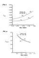
- FIG. 3 and 4 show the coefficient of maximum lift, C1 max , for a prior art SC1095-R8 airfoil 44 to a similar curve 46 representing the performance of a blade utilizing an airfoil according to the present invention.
- the two curves 44, 46 are nearly identical over the range of Mach numbers 0.3 to 0.6 indicating that lift performance of the SC2110 is comparable to the SC1095-R8 airfoil.
- the SC1095-R8 airfoil has been selected for the comparison of Figures 3 and 4 as it is the highest lift rotorcraft airfoil configuration known in the prior art.
- Figure 3 clearly shows the greatest single advantage of the airfoil according to the present invention over the prior art SC1095-R8 high lift airfoil.
- Figure 3 is a plot of the drag coefficient of individual blades at the zero lift orientation, C do , over the range of Mach numbers 0.7 to 0.86.
- the curve of the prior art SC1095-R8 airfoil 48 lies well above the curve 50 which represents the performance of the airfoil according to the present invention.
- the airfoil of the present invention can operate at a significantly higher Mach number before reaching the drag divergence air speed limit above which aerodynamic drag increases rapidly and unacceptably.
- the drag divergence is defined as the air speed at which the ratio of change of the zero lift drag coefficient to the change of Mach number reaches a value of 0.1.
- Figure 5 presents a comparison of the lift and drag performance of the SC2110 airfoil with that of its predecessor configurations.
- the point 56 representing the airfoil according to the present invention has pushed the operating envelope for rotorcraft blades significantly toward the upper right hand corner as compared to the performan ce of the prior art SC1095, SC1095-R8 and SSC-Axx family airfoils 58, 60, 62, signifying an airfoil section which will achieve high lift force over nearly the entire blade airspeed operating range.
- the broad operating range of the airfoil according to the present invention allows a blade 12 to utilize an individual airfoil section over nearly the entire span of the blade, unlike prior art blades wherein airfoil sections had to be matched with expected Mach number in order to avoid undue drag and undesirably high power consumption.
- the airfoil according to the present invention is thus able to be used over that portion of the blade span extending from the central hub 14 to nearly 90% of the span length toward the blade tip 20, providing the high maximum lift characteristics of the SC1095-R8 configuration without experiencing the drag divergence phenomenon inherent in the prior art airfoil shapes.
- the remaining out 10% of the blade span may utilize a prior art SSC-Axx airfoil or other configuration best suited for the high speed tip region wherein the generation of lift is of secondary importance as compared to actual drag.
Abstract
Description
- The present invention relates to a blade for a helicopter, and more particularly, to the airfoil cross section thereof.
- Rotorcraft, such as helicopters, are supported vertically by a plurality of driven blades which rotate about a vertical axis. It will be appreciated that, since both the lift and propulsive force of the helicopter are supplied primarily through the large rotating blade system, it is advantageous to provide a main blade configuration which achieves a high lifting force at a given airspeed and which does not experience a high aerodynamic drag.
- The prior art contains many examples of blades and airfoils attempting to achieve this high lift-low drag performance ideal, most notably U.S. Patent No. 3,728,045 issued April 17, 1973 to Balch, U.S. Patent No. 4,142,837 issued March 6, 1979 to de Simone and U.S. Patent No. 4,569,633 issued February 11, 1986 to Flemming, Jr.
- The Balch airfoil, designated SC1095, provides an airfoil cross section which achieves both higher maximum lift and lower zero lift aerodynamic drag at high velocity conditions as compared to the then-existing airfoils. These improvements were realized by selectively shaping the airfoil surface for both higher lift and lower drag by delaying separation of the airflow boundary layer over the airfoil, as well as decreasing the local Mach number at high freestream velocities.
- The de Simone airfoil, also referred to as the SC1095-R8 configuration, is characterized in the referenced patent as an improvement over the SC1095 airfoil wherein the airfoil upper surface is shaped to distribute the surface static pressure peak over a greater area thereby reducing the likelihood of airfoil boundary layer separation. The SC1095-R8 airfoil achieves higher maximum lift than the SC1095 configuration at lower velocities, but is subject to higher zero lift drag forces at high velocity conditions.
- The Flemming, Jr. configuration is an improvement over the SC1095-R8 design and is particularly well adapted for use in high speed applications, such as in the radially outer tip portion of the main blade. The Flemming, Jr. airfoil, also termed the SSC-Axx family, further reduces the zero lift drag force at high air speeds by delaying the creation of shock waves in the local airflow. This further reduction in aerodynamic drag at high air speed is achieved at the expense of some maximum lift at lower velocity operation.
- As will be apparent from considering the above mentioned references as a group, prior art blade designers combine several types of airfoil cross sections along the span of an individual blade in an attempt to maximize the lift and minimize the drag over the range of expected airflow velocities. For example, U.S. Patent No. 4,248,572 issued February 3, 1981 to Fradenburgh shows a single helicopter blade which utilizes the high lift SC1095-R8 airfoil configuration in the lower velocity central span region of the blade and the lower lift SC1095 airfoil section radially outward thereof in that portion of the blade which encounters higher air velocities. The Flemming, Jr. patent provides a still further modification wherein members of the SSC-Axx family of airfoils is used in the rotor tip portion due to its still greater resistance to shock wave formation at high airflow velocities.
- As can be seen, the twin goals of high lift and low drag in prior art airfoils are exclusionary, leading designers to specify high lift airfoil configurations only in the lower speed regions of the rotorcraft blade while being content with reduced lift in the radially outer high speed portions in order to avoid excessive aerodynamic drag. What is needed is an airfoil configuration able to produce high lift without experiencing unacceptably high drag force under high airflow velocity operation.
- It is therefore an object of the present invention to provide a blade for a rotorcraft which exhibits improved performance in the form of reduced aerodynamic drag while maintaining the maximum lift available in prior art blades.
- It is further an object of the present invention to provide an improved rotor airfoil cross section configured to delay the onset of aerodynamic drag divergence as the airfoil is subjected to increasing velocity airflow over the blade exterior.
- It is further an object of the present invention to provide an improved rotor airfoil cross section which experiences a reduced quarter-chord pitching moment as compared to prior art high lift, low drag configurations, thereby reducing torsional stress within the blade.
- It is further an object of the present invention to provide an improved rotor airfoil cross section which is suited for use in the region of the helicopter blade span extending from the rotor hub to a point approximately 90% of the distance to the blade tip.
- It is still further an object of the present invention to provide a family of similar shaped airfoil cross sections of differing thicknesses for use along the blade span.
- The present invention provides an improved airfoil cross section for use in a rotating helicopter blade or the like and which experiences reduced zero lift aerodynamic drag as compared to prior art airfoil configurations without incurring a penalty in the form of reduced maximum lift. Improved performance is accomplished by altering the leading edge and surface geometry of a prior art, low drag airfoil configuration to increase the maximum lift coefficient without significantly changing the drag coefficient or pitching moment about the quarter chord point.
- More specifically, the forward portion of a prior art SSC-Axx family blade airfoil, the SSC-A10, is thickened and "drooped" slightly, improving the blade lift coefficient. The result is a high lift, low drag airfoil design which obtains the best advantages of prior art designs with a single configuration. The performance of the airfoil section according to the present invention over the range of operating conditions is such that the same family of airfoil shapes may be used along nearly the entire helicopter rotor blade span, preferably in that portion of the span extending from the rotor hub to 90% of the span distance between the hub and the blade tip. A rotorcraft equipped with a rotor blade having an airfoil cross section according to the present invention requires less power to drive the main rotor, especially during periods of high speed horizontal flight in which the advancing rotor blades are subject to high relative velocity airflows.
- Additionally, by providing a reduced quarter-chord pitching moment as compared to prior art high lift blade airfoils, blades utilizing airfoils according to the present invention are subject to less torsional stress along the blade span thereby exhibiting less twisting between the hub and tip sections. Both these and other advantages and features will be apparent to those skilled in the art upon close review of the following specification and the appended claims and drawing figures.
-
- Figure 1 shows a schematic view of a rotating blade for a rotorcraft or the like.
- Figure 2 shows a cross section of the airfoil according to the present invention and a prior art SSC-A10 airfoil cross section.
- Figure 3 is a graphical representation of the relationship between the coefficient of zero lift aerodynamic drag and the Mach number for airfoils according to the present invention and a prior art SC1095-R8 airfoil.
- Figure 4 is a graphical representation of the relationship between the maximum aerodynamic lift coefficient and Mach number for the airfoil according to the present invention and a prior art SC1095-R8 airfoil.
- Figure 5 is a graphical comparison of the maximum lift coefficient and drag divergence number for an airfoil according to the present invention and a series of prior art airfoils.
- Figure 1 shows a schematic of a
helicopter rotor 10 which consists of a plurality of equally spacedblades 12 mounted for rotation with arotor hub 14 about an axis ofrotation 16. Eachblade 12 is preferably identical to the single blade illustrated in Figure 1 and includes aroot portion 18 which connects to thehub 14, atip portion 20 which is that part of the blade farthest from the axis ofrotation 16 and which therefore travels at the highest speed, and acenter portion 22 extending between thehub 14 andtip 20. Each of theblades 12 has a leadingedge 24, atrailing edge 26 and defines a chord dimension C and a span dimension S as shown in Figure 1. Theblade 12 is an airfoil in cross section and generates lift during rotation of theblade 12. - Turning now to Figure 2, a
cross section 28 of the airfoil according to the present invention is shown overlain with across section 30 of a prior art SSC-A10 airfoil. The airfoil according to the present invention, also termed "SC2110", is shown with the leadingedge 24 andtrailing edge 26 defining a chordal distance C therebetween. Figure 2 also shows theairfoil chord line 30 connecting the leading andtrailing edges airfoil section 28 includes anupper surface 34 and alower surface 36 disposed on opposite sides of thechord line 32. - It is conventional to define an individual airfoil shape by setting forth the location of the
upper airfoil surface 34 and thelower airfoil surface 36 at a plurality of stations disposed along theblade chord 32. The SC2110airfoil cross section 28 according to the present invention is defined in Table I which contains a listing of the vertical displacement Y u, Y₁ of the airfoil upper andlower surfaces airfoil chord line 32 from the leadingedge 24 to thetrailing edge 26.
- As with the SSC-A10 airfoil, the SC2110 airfoil is a member of a corresponding family of similar shapes of differing thicknesses as defined by the ratio of airfoil maximum thickness (t max) to airfoil chord (C). The airfoil designations SSC-A10 and SC2110 thus each represent individual members of the respective airfoil families SSC-Axx and SC21xx wherein the ratio of t max to C is approximately 0.10, or 10%. The SC21xx family of airfoils is defined by Table II wherein the vertical displacement of the upper and lower airfoil surfaces is tabulated at a plurality of stations along the
airfoil chord 32, each station defined as in Table I as a proportional displacement X/C of the distance between the blade leading andtrailing edges 
- It has been determined that the advantages of increased performance are still achieved by the SC21xx airfoils generally, and the SC2110 airfoil particularly, if the tabulated quantities vary throughout a range of ± three percent.
- The
airfoil section 28 according to the present invention is a derivative of the SSC-A10 cross section 30 and differs therefrom both in configuration and in performance. The SC2110cross section 28 is significantly thicker than the priorart airfoil section 30 in the leadingedge region 38 and thecentral chord region 40, while being substantially similar in thickness in the trailinged ge region 42. The leading edge, central chord, andtrailing edge regions - It should further be noted that this increased thickness is accompanied by an increased camber or "droop" in the
forward portions upper surface 34 of theSC2110 cross section 28 being located at a greater vertical displacement from theairfoil chord line 32 as compared to the corresponding surface on the prior art SSC-A10 cross section 30. This droop is most accurately expressed as rotation of the prior art SSC-A10 nose of about 3.25° about the X/C = 0.15 chord station. - The dropped configuration of the present invention provides additional lift over the prior art SSC-
A10 airfoil 30, restoring lift performance nearly to that of the SC1095-R8 configuration as discussed in the Background section. The reshaped cross section also evens out the variation of local air velocity and Mach number over the upper surface of theairfoil 30, thereby delaying the formation of sonic shock waves. - The success of the SC2110
airfoil section 28 is evident from Figures 3 and 4 which compare the lift and drag coefficients of individual blades over a range of Mach numbers. Figure 4 shows the coefficient of maximum lift, C₁ max, for a prior art SC1095-R8 airfoil 44 to asimilar curve 46 representing the performance of a blade utilizing an airfoil according to the present invention. The twocurves - Figure 3 clearly shows the greatest single advantage of the airfoil according to the present invention over the prior art SC1095-R8 high lift airfoil. Figure 3 is a plot of the drag coefficient of individual blades at the zero lift orientation, C do, over the range of Mach numbers 0.7 to 0.86. The curve of the prior art SC1095-
R8 airfoil 48 lies well above thecurve 50 which represents the performance of the airfoil according to the present invention. By comparing Figure 3 and 4, it should be readily apparent that a blade utilizing an airfoil according to the present invention provides lifting performance substantially equivalent to that of the best rotorcraft airfoil sections heretofore known in the art while simultaneously inducing less drag in the upper Mach number operating range. - More significantly, the airfoil of the present invention can operate at a significantly higher Mach number before reaching the drag divergence air speed limit above which aerodynamic drag increases rapidly and unacceptably. The drag divergence is defined as the air speed at which the ratio of change of the zero lift drag coefficient to the change of Mach number reaches a value of 0.1. These points are shown in Figure 3 for the
prior art airfoil 52 and the airfoil according to thepresent invention 54 illustrating the advantage of the SC2110 airfoil over the prior art high lift airfoils at high Mach number operation. - Figure 5 presents a comparison of the lift and drag performance of the SC2110 airfoil with that of its predecessor configurations. Figure 5 is a plot of each airfoil section wherein the vertical displacement represents the maximum lift coefficient at a relatively low Mach number, M = 0.3, and the horizontal displacement is equivalent to the drag divergence Mach number (M dd). As will be appreciated by those skilled in the art, the point 56 representing the airfoil according to the present invention has pushed the operating envelope for rotorcraft blades significantly toward the upper right hand corner as compared to the performan ce of the prior art SC1095, SC1095-R8 and SSC-Axx family airfoils 58, 60, 62, signifying an airfoil section which will achieve high lift force over nearly the entire blade airspeed operating range.
- The broad operating range of the airfoil according to the present invention allows a
blade 12 to utilize an individual airfoil section over nearly the entire span of the blade, unlike prior art blades wherein airfoil sections had to be matched with expected Mach number in order to avoid undue drag and undesirably high power consumption. The airfoil according to the present invention is thus able to be used over that portion of the blade span extending from thecentral hub 14 to nearly 90% of the span length toward theblade tip 20, providing the high maximum lift characteristics of the SC1095-R8 configuration without experiencing the drag divergence phenomenon inherent in the prior art airfoil shapes. - The remaining out 10% of the blade span may utilize a prior art SSC-Axx airfoil or other configuration best suited for the high speed tip region wherein the generation of lift is of secondary importance as compared to actual drag.
- It is thus apparent that the
airfoil cross section 28 according to the present invention is well suited to achieve the objects and advantages as set forth hereinabove, and it will further be appreciated by those skilled in the art that various minor modifications may be made from the configuration as presented without departing from the spirit and scope of the invention as described and claimed.
Claims (5)

X is the linear displacement along a chord line extending between the airfoil leading edge and the airfoil trailing edge;
C is the chordal length of the airfoil cross section measured between the leading and the trailing edges;
Y u is the transverse displacement of the airfoil upper surface from the chord line; and
Y₁ is the transverse displacement of the airfoil lower surface from the chord line.
the high lift-low drag airfoil section is defined within that portion of the blade extending spanwisely from the root end to at least 90% of the distance to the tip end.

X is the linear displacement along a chord line extending between the airfoil leading edge and the airfoil trailing edge;
C is the chordal length of the airfoil cross section measured between the leading and the trailing edges;
Y u is the transverse displacement of the airfoil upper surface from the chord line;
Y₁ is the transverse displacement of the airfoil lower surface from the chord line; and
t max is the maximum transverse thickness achieved by the airfoil cross section.
Applications Claiming Priority (2)
| Application Number | Priority Date | Filing Date | Title |
|---|---|---|---|
| US903169 | 1986-09-03 | ||
| US06/903,169 US4744728A (en) | 1986-09-03 | 1986-09-03 | Helicopter blade airfoil |
Publications (2)
| Publication Number | Publication Date |
|---|---|
| EP0262071A1 true EP0262071A1 (en) | 1988-03-30 |
| EP0262071B1 EP0262071B1 (en) | 1991-05-08 |
Family
ID=25417055
Family Applications (1)
| Application Number | Title | Priority Date | Filing Date |
|---|---|---|---|
| EP87630148A Expired EP0262071B1 (en) | 1986-09-03 | 1987-08-19 | Helicopter blade airfoil |
Country Status (6)
| Country | Link |
|---|---|
| US (1) | US4744728A (en) |
| EP (1) | EP0262071B1 (en) |
| JP (1) | JP2620087B2 (en) |
| AU (1) | AU598015B2 (en) |
| CA (1) | CA1295310C (en) |
| DE (1) | DE3769903D1 (en) |
Cited By (4)
| Publication number | Priority date | Publication date | Assignee | Title |
|---|---|---|---|---|
| EP0588360A1 (en) * | 1992-09-17 | 1994-03-23 | Mitsubishi Jukogyo Kabushiki Kaisha | Less noisy helicopter |
| DE19528229A1 (en) * | 1994-08-02 | 1996-02-15 | Fuji Heavy Ind Ltd | Rotor blade of a rotary wing aircraft |
| EP0911257A3 (en) * | 1997-10-23 | 2000-02-23 | Advanced Technology Institute of Commuter-Helicopter, Ltd. | Helicopter blade aerofoil |
| GB2363774A (en) * | 2000-06-09 | 2002-01-09 | Cartercopters Llc | Aircraft rotor aerofoil suitable for forward and reverse flow |
Families Citing this family (12)
| Publication number | Priority date | Publication date | Assignee | Title |
|---|---|---|---|---|
| EP0138800B1 (en) * | 1983-08-17 | 1990-05-23 | Oscar Asboth | Air propeller |
| FR2636593B1 (en) * | 1988-09-19 | 1990-11-23 | Aerospatiale | BLADE FOR AIRCRAFT TURNING WING AND TURNING WING COMPRISING SUCH A BLADE |
| JP2728651B2 (en) | 1996-03-08 | 1998-03-18 | 株式会社コミュータヘリコプタ先進技術研究所 | Helicopter blade airfoil |
| JP2955532B2 (en) * | 1997-02-14 | 1999-10-04 | 株式会社コミュータヘリコプタ先進技術研究所 | Helicopter blade airfoil |
| FR2765187B1 (en) | 1997-06-25 | 1999-08-27 | Onera (Off Nat Aerospatiale) | BLADE PROFILE FOR AIRCRAFT ROTATING AIRCRAFT AND BLADE FOR ROTATING AIRCRAFT WITH SUCH A PROFILE |
| JP3051398B1 (en) | 1999-02-23 | 2000-06-12 | 株式会社コミュータヘリコプタ先進技術研究所 | Helicopter blade airfoil and helicopter blade |
| US8842000B2 (en) | 2012-07-17 | 2014-09-23 | 4Front Engineered Solutions, Inc. | Fire control systems |
| US9132914B2 (en) | 2012-07-30 | 2015-09-15 | Sikorsky Aircraft Corporation | Low drag high restoring moment airfoils |
| US9874214B2 (en) | 2014-01-28 | 2018-01-23 | 4Front Engineered Solutions, Inc. | Fan with fan blade mounting structure |
| US9726192B2 (en) | 2015-03-31 | 2017-08-08 | Assa Abloy Entrance Systems Ab | Fan blades and associated blade tips |
| EP3112258B1 (en) * | 2015-07-03 | 2017-09-13 | AIRBUS HELICOPTERS DEUTSCHLAND GmbH | Airfoils for rotor blades of rotary wing aircrafts |
| CN107444611B (en) * | 2017-08-01 | 2020-04-21 | 中国航空工业集团公司西安飞机设计研究所 | General high-lift aircraft wing section |
Citations (4)
| Publication number | Priority date | Publication date | Assignee | Title |
|---|---|---|---|---|
| GB2059373A (en) * | 1979-09-28 | 1981-04-23 | Boeing Co | Advanced airfoils for helicopter rotor application |
| US4412664A (en) * | 1982-06-25 | 1983-11-01 | The United States Of America As Represented By The Administrator Of The National Aeronautics And Space Administration | Family of airfoil shapes for rotating blades |
| US4459083A (en) * | 1979-03-06 | 1984-07-10 | The United States Of America As Represented By The Administrator Of The National Aeronautics And Space Administration | Shapes for rotating airfoils |
| GB2138374A (en) * | 1983-04-18 | 1984-10-24 | United Technologies Corp | Airfoil section for a rotor blade of a rotorcraft |
Family Cites Families (6)
| Publication number | Priority date | Publication date | Assignee | Title |
|---|---|---|---|---|
| US3728045A (en) * | 1971-09-22 | 1973-04-17 | United Aircraft Corp | Helicopter blade |
| US4142837A (en) * | 1977-11-11 | 1979-03-06 | United Technologies Corporation | Helicopter blade |
| US4248572A (en) * | 1978-12-11 | 1981-02-03 | United Technologies Corporation | Helicopter blade |
| DE3310937C2 (en) * | 1982-10-09 | 1984-10-31 | Dornier Gmbh, 7990 Friedrichshafen | Propeller blades, in particular for propelling aircraft |
| FR2536365A1 (en) * | 1982-11-18 | 1984-05-25 | Onera (Off Nat Aerospatiale) | BLADE FOR AIRCRAFT PROPELLER |
| JPS59134096A (en) * | 1983-01-21 | 1984-08-01 | 防衛庁技術研究本部長 | Blade type for rotor blade |
-
1986
- 1986-09-03 US US06/903,169 patent/US4744728A/en not_active Ceased
-
1987
- 1987-07-07 CA CA000541505A patent/CA1295310C/en not_active Expired - Lifetime
- 1987-08-14 AU AU77145/87A patent/AU598015B2/en not_active Ceased
- 1987-08-19 EP EP87630148A patent/EP0262071B1/en not_active Expired
- 1987-08-19 DE DE8787630148T patent/DE3769903D1/en not_active Expired - Lifetime
- 1987-08-21 JP JP62209116A patent/JP2620087B2/en not_active Expired - Lifetime
Patent Citations (4)
| Publication number | Priority date | Publication date | Assignee | Title |
|---|---|---|---|---|
| US4459083A (en) * | 1979-03-06 | 1984-07-10 | The United States Of America As Represented By The Administrator Of The National Aeronautics And Space Administration | Shapes for rotating airfoils |
| GB2059373A (en) * | 1979-09-28 | 1981-04-23 | Boeing Co | Advanced airfoils for helicopter rotor application |
| US4412664A (en) * | 1982-06-25 | 1983-11-01 | The United States Of America As Represented By The Administrator Of The National Aeronautics And Space Administration | Family of airfoil shapes for rotating blades |
| GB2138374A (en) * | 1983-04-18 | 1984-10-24 | United Technologies Corp | Airfoil section for a rotor blade of a rotorcraft |
Cited By (9)
| Publication number | Priority date | Publication date | Assignee | Title |
|---|---|---|---|---|
| EP0588360A1 (en) * | 1992-09-17 | 1994-03-23 | Mitsubishi Jukogyo Kabushiki Kaisha | Less noisy helicopter |
| DE19528229A1 (en) * | 1994-08-02 | 1996-02-15 | Fuji Heavy Ind Ltd | Rotor blade of a rotary wing aircraft |
| GB2292550A (en) * | 1994-08-02 | 1996-02-28 | Fuji Heavy Ind Ltd | Rotor blade for a rotary-wing aircraft |
| GB2292550B (en) * | 1994-08-02 | 1996-10-23 | Fuji Heavy Ind Ltd | Rotor blade for a rotary-wing aircraft |
| US5609472A (en) * | 1994-08-02 | 1997-03-11 | Fuji Jukogyo Kabushiki Kaisha | Rotor blade for a rotary-wing aircraft |
| DE19528229C2 (en) * | 1994-08-02 | 2000-06-08 | Fuji Heavy Ind Ltd | Rotor blade of a rotary wing aircraft |
| EP0911257A3 (en) * | 1997-10-23 | 2000-02-23 | Advanced Technology Institute of Commuter-Helicopter, Ltd. | Helicopter blade aerofoil |
| US6164918A (en) * | 1997-10-23 | 2000-12-26 | Advanced Technology Institute Of Commuter-Helicopter, Ltd. | Helicopter blade aerofoil |
| GB2363774A (en) * | 2000-06-09 | 2002-01-09 | Cartercopters Llc | Aircraft rotor aerofoil suitable for forward and reverse flow |
Also Published As
| Publication number | Publication date |
|---|---|
| US4744728A (en) | 1988-05-17 |
| JP2620087B2 (en) | 1997-06-11 |
| JPS6364894A (en) | 1988-03-23 |
| AU598015B2 (en) | 1990-06-14 |
| CA1295310C (en) | 1992-02-04 |
| EP0262071B1 (en) | 1991-05-08 |
| DE3769903D1 (en) | 1991-06-13 |
| AU7714587A (en) | 1988-03-10 |
Similar Documents
| Publication | Publication Date | Title |
|---|---|---|
| US8172540B2 (en) | Airfoil for a helicopter rotor blade | |
| US8066219B2 (en) | Anhedral tip blades for tiltrotor aircraft | |
| EP0262071B1 (en) | Helicopter blade airfoil | |
| US4519746A (en) | Airfoil blade | |
| US4459083A (en) | Shapes for rotating airfoils | |
| JP3802209B2 (en) | Wing with swept tip for aircraft rotor | |
| EP3178739B1 (en) | Rotor blade twist distribution for a high speed rotary-wing aircraft | |
| EP0331603B1 (en) | Airfoiled blade | |
| CN101501302B (en) | Rotor blade for a high speed rotary-wing aircraft | |
| US4569633A (en) | Airfoil section for a rotor blade of a rotorcraft | |
| EP0878394B1 (en) | Rotor blade for rotary-wing aircraft | |
| EP0517467A1 (en) | Rotary-wing blade of rotary-wing aircraft | |
| EP2508423B1 (en) | Aerofoil | |
| CN110155319B (en) | Method for modifying a blade to increase its negative stall angle of attack | |
| US20160122011A1 (en) | Airfoil for rotor blade with reduced pitching moment | |
| CN111674546B (en) | Rotor wing pneumatic appearance suitable for small and medium-sized unmanned tilt rotor wing aircraft | |
| CN211364914U (en) | Rotor craft's paddle and rotor craft | |
| US4606519A (en) | Airfoil | |
| US5609472A (en) | Rotor blade for a rotary-wing aircraft | |
| USRE33589E (en) | Helicopter blade airfoil | |
| US20050281676A1 (en) | Multi-hedral rotary wing | |
| US20210237862A1 (en) | Rotary-wing aircraft blade airfoil, blade having the blade airfoil, and rotary-wing aircraft including the blade | |
| JPS6317680B2 (en) | ||
| JP2002166891A (en) | High performance wing for blade | |
| CN112918668B (en) | Rotor of rotor craft and rotor craft |
Legal Events
| Date | Code | Title | Description |
|---|---|---|---|
| PUAI | Public reference made under article 153(3) epc to a published international application that has entered the european phase |
Free format text: ORIGINAL CODE: 0009012 |
|
| AK | Designated contracting states |
Kind code of ref document: A1 Designated state(s): DE FR GB IT |
|
| 17P | Request for examination filed |
Effective date: 19880913 |
|
| 17Q | First examination report despatched |
Effective date: 19890807 |
|
| GRAA | (expected) grant |
Free format text: ORIGINAL CODE: 0009210 |
|
| AK | Designated contracting states |
Kind code of ref document: B1 Designated state(s): DE FR GB IT |
|
| ET | Fr: translation filed | ||
| REF | Corresponds to: |
Ref document number: 3769903 Country of ref document: DE Date of ref document: 19910613 |
|
| ITF | It: translation for a ep patent filed |
Owner name: UFFICIO BREVETTI RICCARDI & C. |
|
| PLBE | No opposition filed within time limit |
Free format text: ORIGINAL CODE: 0009261 |
|
| STAA | Information on the status of an ep patent application or granted ep patent |
Free format text: STATUS: NO OPPOSITION FILED WITHIN TIME LIMIT |
|
| 26N | No opposition filed | ||
| REG | Reference to a national code |
Ref country code: GB Ref legal event code: IF02 |
|
| PGFP | Annual fee paid to national office [announced via postgrant information from national office to epo] |
Ref country code: GB Payment date: 20060706 Year of fee payment: 20 |
|
| PGFP | Annual fee paid to national office [announced via postgrant information from national office to epo] |
Ref country code: FR Payment date: 20060803 Year of fee payment: 20 |
|
| PGFP | Annual fee paid to national office [announced via postgrant information from national office to epo] |
Ref country code: IT Payment date: 20060831 Year of fee payment: 20 Ref country code: DE Payment date: 20060831 Year of fee payment: 20 |
|
| REG | Reference to a national code |
Ref country code: GB Ref legal event code: PE20 |
|
| PG25 | Lapsed in a contracting state [announced via postgrant information from national office to epo] |
Ref country code: GB Free format text: LAPSE BECAUSE OF EXPIRATION OF PROTECTION Effective date: 20070818 |