EP0261952B1 - Shut-off valve for juice dispensing system - Google Patents
Shut-off valve for juice dispensing system Download PDFInfo
- Publication number
- EP0261952B1 EP0261952B1 EP87308426A EP87308426A EP0261952B1 EP 0261952 B1 EP0261952 B1 EP 0261952B1 EP 87308426 A EP87308426 A EP 87308426A EP 87308426 A EP87308426 A EP 87308426A EP 0261952 B1 EP0261952 B1 EP 0261952B1
- Authority
- EP
- European Patent Office
- Prior art keywords
- sleeve
- housing
- valve connector
- juice
- passageway
- Prior art date
- Legal status (The legal status is an assumption and is not a legal conclusion. Google has not performed a legal analysis and makes no representation as to the accuracy of the status listed.)
- Expired - Lifetime
Links
- 235000011389 fruit/vegetable juice Nutrition 0.000 title claims description 16
- 230000008878 coupling Effects 0.000 claims description 7
- 238000010168 coupling process Methods 0.000 claims description 7
- 238000005859 coupling reaction Methods 0.000 claims description 7
- 230000006835 compression Effects 0.000 claims description 2
- 238000007906 compression Methods 0.000 claims description 2
- 239000012141 concentrate Substances 0.000 description 14
- 235000015205 orange juice Nutrition 0.000 description 7
- 235000013405 beer Nutrition 0.000 description 4
- 235000021579 juice concentrates Nutrition 0.000 description 3
- 235000013365 dairy product Nutrition 0.000 description 2
- 230000005484 gravity Effects 0.000 description 2
- XLYOFNOQVPJJNP-UHFFFAOYSA-N water Substances O XLYOFNOQVPJJNP-UHFFFAOYSA-N 0.000 description 2
- 235000013361 beverage Nutrition 0.000 description 1
- 239000003085 diluting agent Substances 0.000 description 1
- 239000008267 milk Substances 0.000 description 1
- 235000013336 milk Nutrition 0.000 description 1
- 210000004080 milk Anatomy 0.000 description 1
- 238000012986 modification Methods 0.000 description 1
- 230000004048 modification Effects 0.000 description 1
- 239000011087 paperboard Substances 0.000 description 1
- 238000005086 pumping Methods 0.000 description 1
Images


Classifications
-
- B—PERFORMING OPERATIONS; TRANSPORTING
- B67—OPENING, CLOSING OR CLEANING BOTTLES, JARS OR SIMILAR CONTAINERS; LIQUID HANDLING
- B67D—DISPENSING, DELIVERING OR TRANSFERRING LIQUIDS, NOT OTHERWISE PROVIDED FOR
- B67D1/00—Apparatus or devices for dispensing beverages on draught
-
- B—PERFORMING OPERATIONS; TRANSPORTING
- B67—OPENING, CLOSING OR CLEANING BOTTLES, JARS OR SIMILAR CONTAINERS; LIQUID HANDLING
- B67D—DISPENSING, DELIVERING OR TRANSFERRING LIQUIDS, NOT OTHERWISE PROVIDED FOR
- B67D1/00—Apparatus or devices for dispensing beverages on draught
- B67D1/08—Details
- B67D1/12—Flow or pressure control devices or systems, e.g. valves, gas pressure control, level control in storage containers
- B67D1/14—Reducing valves or control taps
- B67D1/1405—Control taps
- B67D1/1438—Control taps comprising a valve shutter movable in a direction parallel to the valve seat, e.g. sliding or rotating
-
- B—PERFORMING OPERATIONS; TRANSPORTING
- B67—OPENING, CLOSING OR CLEANING BOTTLES, JARS OR SIMILAR CONTAINERS; LIQUID HANDLING
- B67D—DISPENSING, DELIVERING OR TRANSFERRING LIQUIDS, NOT OTHERWISE PROVIDED FOR
- B67D1/00—Apparatus or devices for dispensing beverages on draught
- B67D1/08—Details
- B67D1/0829—Keg connection means
- B67D1/0831—Keg connection means combined with valves
- B67D1/0835—Keg connection means combined with valves with one valve
Definitions
- This invention relates to postmix juice dispensing and in particular to a shut-off valve connector for a juice dispensing system for pulp-containing juice.
- Postmix orange juice dispensing systems are known in which thawed juice concentrate is mixed, with water in a desired ratio to produce the juice beverage.
- the juice may or may not contain pulp.
- the system is similar to milk dispensing systems and uses dairy bags for the concentrate and a gravity feed system with a simple shut-off valve that is actuated by pushing a beverage cup against a lever arm.
- a simple shut-off valve that is actuated by pushing a beverage cup against a lever arm.
- the prior art dairy bag is empty, it is simply replaced with a new bag.
- the use of juice containing pulp causes many problems because the pulp clogs valves and lines.
- US-A 4 380 310 discloses a shut-off valve connector for a juice dispensing conduit, comprising a housing having an elongate chamber therein, said chamber being open at a proximal end of said housing and having an outlet port in a wall of said housing, a sleeve located in said chamber for reciprocating movement therein between a closed position and an open position, said sleeve having a passageway therethrough including an inlet opening in a proximal end thereof and an outlet opening, and a coupling at the proximal end of said valve connector housing for attaching said valve connector to a container spout.
- EP-A 222 729 discloses an apparatus for dispensing beer including means for changing over the connection of a dispenser from one beer container to another, wherein the flow of beer is not interrupted during change over and the cross-sectional shape of the beer flow passage is constant, with no restrictions therein.
- the shut-off valve connector of the present invention is characterized in that the said outlet port is provided in a side wall of the housing, the said outlet opening in the sleeve is provided in a side wall thereof to mate with the said outlet port when the sleeve is in its said open position, and means are provided for biassing the sleeve into its closed position, attachment of valve connector to a container spout acting to force the said sleeve to move, relative to the said housing, to its said open position, and further characterized in that the said sleeve passageway has a smooth interior surface of substantially uniform circular cross-section along its entire length, with a smoothly curving 90 ° bend therein leading to the said outlet opening.
- Figs. 1-3 show an orange juice shut-off valve connector 10 according to the present invention, connected to the end of an orange juice concentrate conduit 18.
- the valve connector 10 is to be connected to the spout 12 of a bag 14 used in a bag-in-box container system 16 including a paperboard box 17.
- the bag 14 contains orange juice concentrate 19.
- the valve connector 10 is connected by the conduit 18 to a pump 20 which pulls the concentrate from the bag 14 and forces it through a conduit 22 to a dispensing valve connector 24 where it is mixed in the desired ratio with a diluent such as water, fed to the dispensing valve connector 24 through a conduit 26.
- the shut-off valve connector 10 includes a housing 30 having a cylindrical chamber 31 therein for accommodating an axially movable sleeve 32 therein.
- a cap 34 is screwthreadedly connected to the distal end of the housing 30 and a coil compression spring 36 is positioned within the housing between the cap 34 and the sleeve 32 for biasing the sleeve downwardly to a closed position as shown in Fig. 1.
- the sleeve 32 has a concentrate passageway 38 therethrough from an inlet opening 40 to an outlet opening 42.
- the sidewall of the housing 30 includes an outlet port 44 that mates with the outlet opening 42 of the sleeve 32 when the sleeve is in its uppermost or open position shown in Fig. 2.
- a number of O-rings 46 provide a seal between the axially movable sleeve and the housing.
- the valve connector 10 also includes a coupling 50 for use in attaching the valve connector 10 to the existing spout 12 or other fitting of the orange juice bag 14.
- a retainer 52 connected to the housing 30 allows the coupling 50 to rotate, while maintaining it affixed to the housing.
- the coupling is internally screwthreaded to mate with external screw threads on the spout 12.
- the lower end of the sleeve has an O-ring that seals against the inside wall of the spout when the valve connector 10 is connected to the spout.
- the upper or distal end of the sleeve has a shoulder 54 to limit the downward travel of the sleeve in its closed orientation shown in Fig. 1.
- the housing preferably has an integral fitting 56 that mates with the outlet port 44 for connecting the valve connector 10 to the conduit 18.
- the diameter of the passageway 38 is preferably just under one-half inch (1.27cm).
- the bag 14 Prior to connecting the valve connector 10 to the spout 12, the bag 14 would have a cap or lid (not shown) screw threaded onto the spout.
- the housing and sleeve are provided with a key and slot system 60.
- valve connector 10 is attached to the spout 12 of the concentrate bag 14 by screwing the coupling 50 onto the spout.
- the coupling is threaded down onto the spout, the spout contacts the proximal end of the sleeve 32 and pushes it upwardly against the force of the spring 36 to the final position shown in Fig. 2, providing communication between the passageway 38 and the outlet port 44 of the housing 30, so that orange juice concentrate in the bag 14 can flow out of the bag 14 to the pump 20 by the suction created by the pump.
- the pump then pushes the concentrate to the dispensing valve connector 24.
- the passageway 38 is free from any obstruction or areas which may trap pulp in the orange juice concentrate, and is preferably of smooth, uniform, circular cross-section, identical in size and shape to the passageway 58 in the spout 12.
- valve connector 10 Most of the parts of the valve connector 10, except the spring, are preferably made of plastic. While the valve connector 10 was designed for use in a postmix dispensing system, it can also be used in a premix juice dispensing system.
- valve connector 10 can also be used in other postmix juice dispensing systems than the system described above, that is, it is not limited to use with a pump as the means for moving the concentrate through the concentrate conduit, nor to use with thawed concentrate since it can also be used with unthawed 5+1 concentrate at -10°F to 0°F (249.82 K to 255.38K), for example.
- a dispensing valve connector 24 it can also be fed to a reservoir of a gravity fed juice dispensing system, having for example, a float controlled automatic filling arrangement.
- the present invention at least in its preferred forms, provides a shut-off valve connector for pulp-containing juice that will not clog up; and furthermore which permits the pumping of viscous, pulp-containing juice concentrate from a container, without spilling concentrate when switching bags.
Landscapes
- Devices For Dispensing Beverages (AREA)
- Sliding Valves (AREA)
- Beverage Vending Machines With Cups, And Gas Or Electricity Vending Machines (AREA)
- Valve Housings (AREA)
Description
- This invention relates to postmix juice dispensing and in particular to a shut-off valve connector for a juice dispensing system for pulp-containing juice.
- Postmix orange juice dispensing systems are known in which thawed juice concentrate is mixed, with water in a desired ratio to produce the juice beverage. The juice may or may not contain pulp. The system is similar to milk dispensing systems and uses dairy bags for the concentrate and a gravity feed system with a simple shut-off valve that is actuated by pushing a beverage cup against a lever arm. When the prior art dairy bag is empty, it is simply replaced with a new bag. The use of juice containing pulp causes many problems because the pulp clogs valves and lines.
- US-A 4 380 310 discloses a shut-off valve connector for a juice dispensing conduit, comprising a housing having an elongate chamber therein, said chamber being open at a proximal end of said housing and having an outlet port in a wall of said housing, a sleeve located in said chamber for reciprocating movement therein between a closed position and an open position, said sleeve having a passageway therethrough including an inlet opening in a proximal end thereof and an outlet opening, and a coupling at the proximal end of said valve connector housing for attaching said valve connector to a container spout.
- EP-A 222 729 discloses an apparatus for dispensing beer including means for changing over the connection of a dispenser from one beer container to another, wherein the flow of beer is not interrupted during change over and the cross-sectional shape of the beer flow passage is constant, with no restrictions therein.
- The shut-off valve connector of the present invention is characterized in that the said outlet port is provided in a side wall of the housing, the said outlet opening in the sleeve is provided in a side wall thereof to mate with the said outlet port when the sleeve is in its said open position, and means are provided for biassing the sleeve into its closed position, attachment of valve connector to a container spout acting to force the said sleeve to move, relative to the said housing, to its said open position, and further characterized in that the said sleeve passageway has a smooth interior surface of substantially uniform circular cross-section along its entire length, with a smoothly curving 90° bend therein leading to the said outlet opening.
- An embodiment of the invention will now be described by way of example and with reference to the accompanying drawings, in which:-
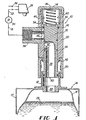
- Fig. 1 is a partly diagrammatic illustration of a dispensing system of the present invention, including a cross-sectional side view of a shut-off valve connector according to the invention, in its closed orientation;
- Fig. 2 is a cross-sectional side view of the valve connector shown in Fig. 1 but shown in its open orientation; and
- Fig. 3 is a cross-sectional view taken along line 3-3 of Fig. 2.
- With reference now to the drawings, Figs. 1-3 show an orange juice shut-off
valve connector 10 according to the present invention, connected to the end of an orangejuice concentrate conduit 18. Thevalve connector 10 is to be connected to thespout 12 of abag 14 used in a bag-in-box container system 16 including apaperboard box 17. Thebag 14 containsorange juice concentrate 19. Thevalve connector 10 is connected by theconduit 18 to apump 20 which pulls the concentrate from thebag 14 and forces it through aconduit 22 to a dispensingvalve connector 24 where it is mixed in the desired ratio with a diluent such as water, fed to the dispensingvalve connector 24 through aconduit 26. - The shut-off
valve connector 10 includes ahousing 30 having acylindrical chamber 31 therein for accommodating an axiallymovable sleeve 32 therein. Acap 34 is screwthreadedly connected to the distal end of thehousing 30 and acoil compression spring 36 is positioned within the housing between thecap 34 and thesleeve 32 for biasing the sleeve downwardly to a closed position as shown in Fig. 1. Thesleeve 32 has aconcentrate passageway 38 therethrough from an inlet opening 40 to an outlet opening 42. The sidewall of thehousing 30 includes anoutlet port 44 that mates with the outlet opening 42 of thesleeve 32 when the sleeve is in its uppermost or open position shown in Fig. 2. A number of O-rings 46 provide a seal between the axially movable sleeve and the housing. - The
valve connector 10 also includes acoupling 50 for use in attaching thevalve connector 10 to the existingspout 12 or other fitting of theorange juice bag 14. Aretainer 52 connected to thehousing 30 allows thecoupling 50 to rotate, while maintaining it affixed to the housing. The coupling is internally screwthreaded to mate with external screw threads on thespout 12. The lower end of the sleeve has an O-ring that seals against the inside wall of the spout when thevalve connector 10 is connected to the spout. - The upper or distal end of the sleeve has a
shoulder 54 to limit the downward travel of the sleeve in its closed orientation shown in Fig. 1. The housing preferably has anintegral fitting 56 that mates with theoutlet port 44 for connecting thevalve connector 10 to theconduit 18. - The diameter of the
passageway 38 is preferably just under one-half inch (1.27cm). Prior to connecting thevalve connector 10 to thespout 12, thebag 14 would have a cap or lid (not shown) screw threaded onto the spout. To keep the outlet opening 42 in registry with theoutlet port 44, the housing and sleeve are provided with a key andslot system 60. - In operation, the
valve connector 10 is attached to thespout 12 of theconcentrate bag 14 by screwing thecoupling 50 onto the spout. As the coupling is threaded down onto the spout, the spout contacts the proximal end of thesleeve 32 and pushes it upwardly against the force of thespring 36 to the final position shown in Fig. 2, providing communication between thepassageway 38 and theoutlet port 44 of thehousing 30, so that orange juice concentrate in thebag 14 can flow out of thebag 14 to thepump 20 by the suction created by the pump. The pump then pushes the concentrate to the dispensingvalve connector 24. - The
passageway 38 is free from any obstruction or areas which may trap pulp in the orange juice concentrate, and is preferably of smooth, uniform, circular cross-section, identical in size and shape to thepassageway 58 in thespout 12. - While the preferred embodiment of this invention has been described above in detail, it is to be understood that variations and modifications can be made therein without the departing from the scope of the present invention as set forth in the appended claims. Most of the parts of the
valve connector 10, except the spring, are preferably made of plastic. While thevalve connector 10 was designed for use in a postmix dispensing system, it can also be used in a premix juice dispensing system. Thevalve connector 10 can also be used in other postmix juice dispensing systems than the system described above, that is, it is not limited to use with a pump as the means for moving the concentrate through the concentrate conduit, nor to use with thawed concentrate since it can also be used with unthawed 5+1 concentrate at -10°F to 0°F (249.82 K to 255.38K), for example. Alternatively to feeding the juice concentrate to a dispensingvalve connector 24, it can also be fed to a reservoir of a gravity fed juice dispensing system, having for example, a float controlled automatic filling arrangement. - It will thus be seen that the present invention, at least in its preferred forms, provides a shut-off valve connector for pulp-containing juice that will not clog up; and furthermore which permits the pumping of viscous, pulp-containing juice concentrate from a container, without spilling concentrate when switching bags.
Claims (5)
Applications Claiming Priority (2)
| Application Number | Priority Date | Filing Date | Title |
|---|---|---|---|
| US06/910,542 US4757919A (en) | 1986-09-23 | 1986-09-23 | Shut-off valve for juice dispensing system |
| US910542 | 1986-09-23 |
Publications (2)
| Publication Number | Publication Date |
|---|---|
| EP0261952A1 EP0261952A1 (en) | 1988-03-30 |
| EP0261952B1 true EP0261952B1 (en) | 1990-12-19 |
Family
ID=25428963
Family Applications (1)
| Application Number | Title | Priority Date | Filing Date |
|---|---|---|---|
| EP87308426A Expired - Lifetime EP0261952B1 (en) | 1986-09-23 | 1987-09-23 | Shut-off valve for juice dispensing system |
Country Status (11)
| Country | Link |
|---|---|
| US (1) | US4757919A (en) |
| EP (1) | EP0261952B1 (en) |
| JP (1) | JPS63152596A (en) |
| KR (1) | KR930011623B1 (en) |
| AU (1) | AU599700B2 (en) |
| CA (1) | CA1308080C (en) |
| DE (1) | DE3766786D1 (en) |
| HK (1) | HK36893A (en) |
| IE (1) | IE60555B1 (en) |
| MY (1) | MY102358A (en) |
| NZ (1) | NZ221866A (en) |
Families Citing this family (21)
| Publication number | Priority date | Publication date | Assignee | Title |
|---|---|---|---|---|
| US4890642A (en) * | 1988-12-16 | 1990-01-02 | The Coca-Cola Company | Disconnect for a bag valve |
| DE8900306U1 (en) * | 1989-01-12 | 1989-04-13 | Sieger Plastic GmbH, 5160 Düren | Emptying device for packaging containers, especially bag-in-box packaging |
| IT225633Y1 (en) * | 1991-02-18 | 1997-01-13 | Zanussi Elettrodomestici | DISPENSER OF DETERGENTS AND OR LIQUID ADDITIVES FOR WASHING MACHINE |
| US5184652A (en) * | 1991-07-02 | 1993-02-09 | Fan Chin Fu | Universal medication port |
| US5496287A (en) * | 1994-07-05 | 1996-03-05 | Jinotti; Walter J. | Pulmonary suction catheter |
| US6315112B1 (en) * | 1998-12-18 | 2001-11-13 | Smithkline Beecham Corporation | Method and package for storing a pressurized container containing a drug |
| US20030209453A1 (en) * | 2001-06-22 | 2003-11-13 | Herman Craig Steven | Method and package for storing a pressurized container containing a drug |
| US20040089561A1 (en) * | 1999-11-23 | 2004-05-13 | Herman Craig Steven | Method and package for storing a pressurized container containing a drug |
| GB0015043D0 (en) * | 2000-06-21 | 2000-08-09 | Glaxo Group Ltd | Medicament dispenser |
| US6708741B1 (en) | 2000-08-24 | 2004-03-23 | Ocean Spray Cranberries, Inc. | Beverage dispenser |
| DE10209422A1 (en) * | 2002-03-05 | 2003-09-25 | Feige Abfuelltechnik | Machine for filling containers with different liquids comprises weighing station with scales for each container, filling nozzle being connected to different pipes, each of which conveys different liquid |
| US6902144B2 (en) * | 2003-01-10 | 2005-06-07 | Colder Products Company | Connector apparatus with seal protector and method of the same |
| US7080665B2 (en) * | 2003-09-09 | 2006-07-25 | Colder Products Company | Connector apparatus and method of coupling bioprocessor equipment to a media source |
| US20080111088A1 (en) * | 2006-11-10 | 2008-05-15 | Roper Pump Company | Self-contained relief valve adjustment device |
| DE102012206163A1 (en) * | 2012-04-16 | 2013-10-17 | BSH Bosch und Siemens Hausgeräte GmbH | Food processor with a liquid outlet |
| ITTV20120114A1 (en) * | 2012-06-12 | 2013-12-13 | Francesco Boscarato | "MODULAR DISPENSER CONTAINER FOR THE DELIVERY AND CONSERVATION OF FOOD LIQUIDS" |
| ITMI20131302A1 (en) * | 2013-08-01 | 2015-02-02 | Fluid O Tech Srl | INFUSION VALVE FOR DRINKING AND PRODUCTION MACHINES |
| RS57285B1 (en) * | 2014-05-23 | 2018-08-31 | Carlsberg Breweries As | Beverage dispensing assembly with flexible valve |
| JP2016030616A (en) * | 2014-07-28 | 2016-03-07 | Next Innovation合同会社 | Joint mechanism |
| CN107762691A (en) * | 2017-09-19 | 2018-03-06 | 北汽福田汽车股份有限公司 | Pipe connecting component and vehicle |
| CN110294448A (en) * | 2018-03-22 | 2019-10-01 | 广州腾工电子科技有限公司 | The anti-blocking beverage dispenser of discharge port |
Citations (1)
| Publication number | Priority date | Publication date | Assignee | Title |
|---|---|---|---|---|
| EP0222729A2 (en) * | 1985-11-11 | 1987-05-20 | WALLA MASCHINEN Gesellschaft m.b.H. & Co | Beer-tapping device |
Family Cites Families (16)
| Publication number | Priority date | Publication date | Assignee | Title |
|---|---|---|---|---|
| US580375A (en) * | 1897-04-13 | Bottle | ||
| US1990262A (en) * | 1933-11-28 | 1935-02-05 | Bailey John Amity | Device for poisoning rodents |
| US2028175A (en) * | 1934-02-14 | 1936-01-21 | Sheridan C Waite | Dispensing tube |
| US2112125A (en) * | 1934-09-24 | 1938-03-22 | Bultzingslowen Bruno Von | Closure |
| US2536428A (en) * | 1947-03-14 | 1951-01-02 | Air Liquide | Self-closing valve |
| US2753195A (en) * | 1953-07-14 | 1956-07-03 | William D Palmer | Self-sealing coupling |
| FR1190757A (en) * | 1957-01-25 | 1959-10-15 | Sealing device for flexible tubes and similar containers intended to contain a pasty product | |
| FR1528061A (en) * | 1967-04-28 | 1968-06-07 | Device for drawing off beer with incorporated plunger | |
| CA1066675A (en) * | 1976-11-11 | 1979-11-20 | Arthur W. Kulis | Dual juice dispenser |
| BE872454A (en) * | 1978-12-01 | 1979-06-01 | Pierre Antoine S P R L Ets | WITHDRAWAL AND RINSING DEVICE FOR BEER FLOW SYSTEMS |
| US4286636A (en) * | 1979-07-19 | 1981-09-01 | The Coca-Cola Company | Dip tube and valve with quick-disconnect coupling for a collapsible container |
| US4366816A (en) * | 1980-12-22 | 1983-01-04 | Abbott Laboratories | Combination quick disconnect coupling and fluid cutoff valve |
| US4381099A (en) * | 1981-04-28 | 1983-04-26 | The Penmont Company | Faucet for frozen carbonated beverage machine |
| US4380310A (en) * | 1981-07-23 | 1983-04-19 | Container Technologies, Inc. | Flexible container with displaceable fitting and probe coupler apparatus |
| US4510969A (en) * | 1982-01-15 | 1985-04-16 | Alco Foodservice Equipment Company | Connector for pressurized source of beverage concentrate |
| US4606476A (en) * | 1985-06-17 | 1986-08-19 | Pocock Richard L | System for sanitizing beverage dispensing systems |
-
1986
- 1986-09-23 US US06/910,542 patent/US4757919A/en not_active Expired - Fee Related
-
1987
- 1987-09-16 MY MYPI87001684A patent/MY102358A/en unknown
- 1987-09-16 AU AU78453/87A patent/AU599700B2/en not_active Ceased
- 1987-09-21 NZ NZ221866A patent/NZ221866A/en unknown
- 1987-09-22 JP JP62236425A patent/JPS63152596A/en active Pending
- 1987-09-22 CA CA000547539A patent/CA1308080C/en not_active Expired - Lifetime
- 1987-09-22 IE IE255487A patent/IE60555B1/en not_active IP Right Cessation
- 1987-09-22 KR KR1019870010515A patent/KR930011623B1/en not_active IP Right Cessation
- 1987-09-23 DE DE8787308426T patent/DE3766786D1/en not_active Expired - Lifetime
- 1987-09-23 EP EP87308426A patent/EP0261952B1/en not_active Expired - Lifetime
-
1993
- 1993-04-15 HK HK368/93A patent/HK36893A/en unknown
Patent Citations (1)
| Publication number | Priority date | Publication date | Assignee | Title |
|---|---|---|---|---|
| EP0222729A2 (en) * | 1985-11-11 | 1987-05-20 | WALLA MASCHINEN Gesellschaft m.b.H. & Co | Beer-tapping device |
Also Published As
| Publication number | Publication date |
|---|---|
| DE3766786D1 (en) | 1991-01-31 |
| KR930011623B1 (en) | 1993-12-16 |
| MY102358A (en) | 1992-06-17 |
| HK36893A (en) | 1993-04-23 |
| IE872554L (en) | 1988-03-23 |
| AU599700B2 (en) | 1990-07-26 |
| IE60555B1 (en) | 1994-07-27 |
| AU7845387A (en) | 1988-03-31 |
| EP0261952A1 (en) | 1988-03-30 |
| KR880004407A (en) | 1988-06-03 |
| US4757919A (en) | 1988-07-19 |
| JPS63152596A (en) | 1988-06-25 |
| NZ221866A (en) | 1989-11-28 |
| CA1308080C (en) | 1992-09-29 |
Similar Documents
| Publication | Publication Date | Title |
|---|---|---|
| EP0261952B1 (en) | Shut-off valve for juice dispensing system | |
| US4785974A (en) | System for serving a pre-mix beverage or making and serving a post-mix beverage in the zero gravity conditions of outer space | |
| US5082143A (en) | Automatic control system for accurately dispensing mixed drinks | |
| US8578979B2 (en) | Process for dispensing fluid with a slider valve fitment and collar | |
| CA1274489A (en) | Low-cost post-mix beverge dispenser and syrup supply system therefor | |
| US4316557A (en) | Beverage dispenser with removable tank connection means | |
| EP0156500A1 (en) | Fluid dispensing assembly | |
| US5205440A (en) | Dispensing valve/coupling assembly | |
| US5601210A (en) | Tap for dispensing a drink made from a concentrate, and drinks dispenser apparatus equipped with such a tap | |
| US3868049A (en) | Keg tapping device | |
| AU651598B2 (en) | Dilution station | |
| EP0448643B1 (en) | A disconnect for a bag valve | |
| US6003542A (en) | Automatic shutoff valve | |
| EP0266202A1 (en) | Juice dispensing system | |
| US4892125A (en) | System for serving a pre-mix beverage or making and serving a post-mix beverage in the zero gravity conditions of outer space | |
| AU4242397A (en) | Beer foam reducing apparatus | |
| US6076703A (en) | Dispensing device and container assembly comprising such device | |
| US6499518B2 (en) | Nonoverflow, magnetic float valve assembly | |
| US4917831A (en) | Buoyant tank carbonator pump control for post-mix beverage apparatus | |
| US20040124216A1 (en) | Self-contained octopus adaptor tap | |
| CN117597302A (en) | Connector for fluid dispenser |
Legal Events
| Date | Code | Title | Description |
|---|---|---|---|
| PUAI | Public reference made under article 153(3) epc to a published international application that has entered the european phase |
Free format text: ORIGINAL CODE: 0009012 |
|
| AK | Designated contracting states |
Kind code of ref document: A1 Designated state(s): DE GB IT SE |
|
| 17P | Request for examination filed |
Effective date: 19880701 |
|
| 17Q | First examination report despatched |
Effective date: 19890713 |
|
| GRAA | (expected) grant |
Free format text: ORIGINAL CODE: 0009210 |
|
| AK | Designated contracting states |
Kind code of ref document: B1 Designated state(s): DE GB IT SE |
|
| ITF | It: translation for a ep patent filed | ||
| REF | Corresponds to: |
Ref document number: 3766786 Country of ref document: DE Date of ref document: 19910131 |
|
| ITTA | It: last paid annual fee | ||
| PLBE | No opposition filed within time limit |
Free format text: ORIGINAL CODE: 0009261 |
|
| STAA | Information on the status of an ep patent application or granted ep patent |
Free format text: STATUS: NO OPPOSITION FILED WITHIN TIME LIMIT |
|
| 26N | No opposition filed | ||
| PGFP | Annual fee paid to national office [announced via postgrant information from national office to epo] |
Ref country code: SE Payment date: 19940822 Year of fee payment: 8 |
|
| PGFP | Annual fee paid to national office [announced via postgrant information from national office to epo] |
Ref country code: GB Payment date: 19940916 Year of fee payment: 8 |
|
| PGFP | Annual fee paid to national office [announced via postgrant information from national office to epo] |
Ref country code: DE Payment date: 19940929 Year of fee payment: 8 |
|
| EAL | Se: european patent in force in sweden |
Ref document number: 87308426.3 |
|
| PG25 | Lapsed in a contracting state [announced via postgrant information from national office to epo] |
Ref country code: GB Effective date: 19950923 |
|
| PG25 | Lapsed in a contracting state [announced via postgrant information from national office to epo] |
Ref country code: SE Effective date: 19950924 |
|
| GBPC | Gb: european patent ceased through non-payment of renewal fee |
Effective date: 19950923 |
|
| PG25 | Lapsed in a contracting state [announced via postgrant information from national office to epo] |
Ref country code: DE Effective date: 19960601 |
|
| EUG | Se: european patent has lapsed |
Ref document number: 87308426.3 |
|
| PG25 | Lapsed in a contracting state [announced via postgrant information from national office to epo] |
Ref country code: IT Free format text: LAPSE BECAUSE OF NON-PAYMENT OF DUE FEES;WARNING: LAPSES OF ITALIAN PATENTS WITH EFFECTIVE DATE BEFORE 2007 MAY HAVE OCCURRED AT ANY TIME BEFORE 2007. THE CORRECT EFFECTIVE DATE MAY BE DIFFERENT FROM THE ONE RECORDED. Effective date: 20050923 |