EP0261563B1 - Einrichtung zur Inspektion von Kernreaktor-Brennstäben - Google Patents
Einrichtung zur Inspektion von Kernreaktor-Brennstäben Download PDFInfo
- Publication number
- EP0261563B1 EP0261563B1 EP87113508A EP87113508A EP0261563B1 EP 0261563 B1 EP0261563 B1 EP 0261563B1 EP 87113508 A EP87113508 A EP 87113508A EP 87113508 A EP87113508 A EP 87113508A EP 0261563 B1 EP0261563 B1 EP 0261563B1
- Authority
- EP
- European Patent Office
- Prior art keywords
- shaft
- probe
- probes
- fuel
- spindle
- Prior art date
- Legal status (The legal status is an assumption and is not a legal conclusion. Google has not performed a legal analysis and makes no representation as to the accuracy of the status listed.)
- Expired - Lifetime
Links
- 238000007689 inspection Methods 0.000 title claims description 9
- 239000003758 nuclear fuel Substances 0.000 title claims description 3
- 238000009434 installation Methods 0.000 title 1
- 239000000523 sample Substances 0.000 claims description 74
- 239000000446 fuel Substances 0.000 claims description 56
- 238000012360 testing method Methods 0.000 claims description 18
- 238000003780 insertion Methods 0.000 claims description 11
- 230000037431 insertion Effects 0.000 claims description 11
- 230000006835 compression Effects 0.000 claims description 4
- 238000007906 compression Methods 0.000 claims description 4
- 238000002592 echocardiography Methods 0.000 claims description 3
- 238000002604 ultrasonography Methods 0.000 description 6
- 238000010998 test method Methods 0.000 description 2
- XLYOFNOQVPJJNP-UHFFFAOYSA-N water Substances O XLYOFNOQVPJJNP-UHFFFAOYSA-N 0.000 description 2
- 0 C=C1C*CC1 Chemical compound C=C1C*CC1 0.000 description 1
- 230000000712 assembly Effects 0.000 description 1
- 238000000429 assembly Methods 0.000 description 1
- 238000005452 bending Methods 0.000 description 1
- 238000012937 correction Methods 0.000 description 1
- 230000002950 deficient Effects 0.000 description 1
- 238000013461 design Methods 0.000 description 1
- 238000006073 displacement reaction Methods 0.000 description 1
- 230000005855 radiation Effects 0.000 description 1
Images
Classifications
-
- G—PHYSICS
- G01—MEASURING; TESTING
- G01B—MEASURING LENGTH, THICKNESS OR SIMILAR LINEAR DIMENSIONS; MEASURING ANGLES; MEASURING AREAS; MEASURING IRREGULARITIES OF SURFACES OR CONTOURS
- G01B5/00—Measuring arrangements characterised by the use of mechanical techniques
- G01B5/0002—Arrangements for supporting, fixing or guiding the measuring instrument or the object to be measured
-
- G—PHYSICS
- G21—NUCLEAR PHYSICS; NUCLEAR ENGINEERING
- G21C—NUCLEAR REACTORS
- G21C17/00—Monitoring; Testing ; Maintaining
- G21C17/06—Devices or arrangements for monitoring or testing fuel or fuel elements outside the reactor core, e.g. for burn-up, for contamination
-
- Y—GENERAL TAGGING OF NEW TECHNOLOGICAL DEVELOPMENTS; GENERAL TAGGING OF CROSS-SECTIONAL TECHNOLOGIES SPANNING OVER SEVERAL SECTIONS OF THE IPC; TECHNICAL SUBJECTS COVERED BY FORMER USPC CROSS-REFERENCE ART COLLECTIONS [XRACs] AND DIGESTS
- Y02—TECHNOLOGIES OR APPLICATIONS FOR MITIGATION OR ADAPTATION AGAINST CLIMATE CHANGE
- Y02E—REDUCTION OF GREENHOUSE GAS [GHG] EMISSIONS, RELATED TO ENERGY GENERATION, TRANSMISSION OR DISTRIBUTION
- Y02E30/00—Energy generation of nuclear origin
- Y02E30/30—Nuclear fission reactors
Definitions
- the invention relates to a device for the inspection of nuclear reactor fuel rods, which are combined as fuel bundles in a fuel assembly, fingers of a test probe equipped with ultrasonic test heads being able to be moved into the spaces between the fuel rods in several planes.
- Such a device is known from DE-OS 34 19 765.
- the probe can be moved parallel to the longitudinal extension of the fuel assembly in order to enable inspection in several planes.
- the vertical movement of the probe over several meters (a fuel element is about four meters long) requires a precise and therefore complex spindle drive.
- the fuel assembly and thus also the device are arranged in a water reservoir for reasons of radiation protection.
- the vertical movement of the probe in the various test levels can therefore only take place slowly.
- the required vertical movement of the probe in particular contributes to a considerable expenditure of time. Since the fuel rods are inspected when the reactor plant is switched off, the inspection time is lost due to the availability of the nuclear power plant.
- the task is to reduce the inspection effort, but still ensure precise positioning of the probe in the direction of the rooms to be traversed.
- This object is achieved according to the invention in that a separate test probe is provided for each level and in that the retracted position of each test probe can be corrected independently of the retracted position of the other test probes before the test probes are retracted. This ensures that the fuel element is skewed or the fuel rods are bent (deviation from the normal) without any problems, i.e. is mastered without the risk of a test probe starting on a fuel rod.
- the separate positioning enables simultaneous testing on several levels.
- a preferred embodiment provides that a frame holds the probes assigned to the different levels, that the frame can be moved together with the probes in the direction of insertion of the probes and that the probes of all levels can be moved transversely to the direction of entry by means of a common drive.
- This simply constructed frame which does not take up more space than the known device with vertically movable probes, allows the probe to be moved together both in the direction of retraction and transversely thereto.
- At least two spindle nuts extending parallel to one another are attached to an underside of the frame, that spindles mounted in brackets of a support plate engage in the spindle nuts and serve both to move the frame and to support it.
- the frame carries a shaft formed in its central region as a spindle in each plane, that the shaft receives a probe carrier acting as a spindle nut in its central region, that the central region is delimited by two spars which are fixed relative to the shaft are and project at least by the dimension of a fuel rod diameter in the same direction as the fingers of the probe from the shaft, that the distance between the spars is equal to the target width of a fuel assembly and that the shaft is displaceable relative to its bearings.
- Simple mechanical aids enable the probes to be tracked in the case of fuel elements that deviate from the normal in their vertical extension.
- the shaft passes through its bearing points arranged in opposite side walls of the frame, that the free ends protruding from the side walls are provided with an abutment and that between the abutment and the respective side wall Compression spring is arranged.
- a further embodiment of the device provides that each shaft is assigned a worm wheel, which enters into a tongue and groove connection with the shaft and that a worm shaft extending transversely to the shafts engages in all worm wheels at the same time. After the position of the probes arranged in the individual levels can be corrected, the uniform movement of all probes is now ensured on their way from one intermediate space to the next.
- the tongue and groove connection allows the shaft to move axially relative to the worm wheel.
- Each worm wheel is preferably limited in its axial direction of movement in a hub assigned to the frame frames.
- the lateral fixation of the worm wheel prevents the same from carrying out the axial movement of the shaft.
- Another embodiment provides that two struts extending parallel to one another and to the fuel element protrude from a mounting plate for a fuel element, that a spindle drive assigned to each plane extends transversely to the struts between the struts, and that a probe carrier is attached to a spindle nut assigned to each spindle drive is on which a drive element for the movement of the probe into the spaces between the fuel rods is arranged.
- the probes of the different levels can be positioned independently of one another and the entry movement can be carried out independently of one another.
- the positioning of the probes is achieved in a simple manner in that a bar provided for guiding the probe fingers carries an ultrasound transducer between the probe fingers, that the transducer transmits sound waves in the direction of the Sends out the direction of entry and that the returning echoes serve to determine the position of the probe relative to a fuel rod.
- the transducer designed as a transmitter and receiver receives a maximum echo when the center of the probe meets the center of the sonicated fuel rod. The entry movement of the respective probe can then take place immediately.
- Another embodiment provides that a further strut arrangement is provided which is offset by 90 ° to the first and which carries further probes on planes offset from the first strut arrangement. This enables simultaneous testing of a fuel assembly from two sides.
- FIGS. 1 to 6 The invention is described on the basis of two exemplary embodiments and the drawings of FIGS. 1 to 6.
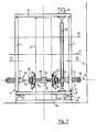
- FIGS. 1 and 2 An inspection device shown in FIGS. 1 and 2 is arranged together with a fuel element 1 to be tested in a water-filled pool indicated by 2.
- the inspection device has a frame 3 which consists of parallel, oppositely arranged side walls 4, on the end faces 5 of which a base 7 and a cover plate 8 are fastened via connecting elements 6.
- a base 7 and a cover plate 8 On the underside of the base plate 7, two spindle nuts 10 are articulated via screws 9.
- parallel spindles 11 are guided by two spindle drives 12, which are mounted in brackets 13.
- the brackets 13 are welded to a support plate 14, which in turn is supported on the bottom of the basin 2.
- the spindle drives 12 thus advantageously serve both to move the frame 3 in the arrow direction 15 and to support it.
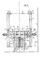
- a shaft 19 passes through the opposite side walls 4 of the frame 3.
- the opposite bearing points 20 of the respective shaft 19 are formed by bearing brackets 21 which are screwed to the side walls. With its free ends, the shaft 19 passes through both the respective bearing 20 and the respective side wall 4.
- the free shaft end carries an abutment (21) 58.
- a compression spring 22 is arranged between the abutment and the outwardly facing surface of a side wall 4 allows the shaft 19 to move in its axial direction within a predetermined range.
- a central part 23 of the shaft 19 designed as a threaded spindle is delimited by a disk 24 fastened on the shaft 19.
- Each disc 24 carries a spar 25 which projects from the shaft 19 in the same direction as the fingers 26 of a probe 27.
- a spindle nut which engages in the thread of the central part 23 is designed as a probe carrier 28 and thus allows the probes to be moved in the axial direction Shaft 19 as soon as this shaft is rotated.
- a rod 29 is arranged parallel to the shaft 19 and is also mounted in the bearing bracket 21 (FIG. 2). The rod 29 penetrates the side of the spars 25 and the probe carrier 28 facing away from the fuel element in a kind of plain bearing connection. It thus serves to lock the spars and probe carrier and to guide these components as they move in the axial direction of the shaft 19.
- the shaft 19 with the components assigned to it is only shown in detail for the level 16 in FIG. It is also designed for levels 17 and 18 and is therefore indicated there only by a dash-dotted line.
- a worm wheel 31 is assigned to each shaft 19 via a tongue and groove connection 30.
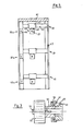
- a union nut 59 engages over a hub 60 of the bearing point 20 in such a way that an annular gap 61 is formed which receives a collar 62 of the worm wheel body with a predetermined play (FIG. 3). This ensures that the worm wheel is limited in its axial movement. In contrast, the hub 60 does not prevent it from rotating.
- the tongue and groove connection 30 is equipped with such play that an axial movement of the shaft 19 relative to the worm wheel is possible when the worm wheel 31 is stationary.
- a worm shaft 32 engages in each worm wheel 31, which extends between the base plate 7 and the cover plate 8 and is supported at bearing points fastened there. The worm shaft 32 is set in rotation by a drive 33 and allows the simultaneous adjustment of the special supports arranged in different planes 16, 17, 18 in the axial direction of the shaft 19.
- the fuel element 1 to be tested is fixed in the pool 2 or directly on the support plate 14 in a manner not shown in the area of the recess 34 of the support plate 14, so that the position between the frame 3 and the fuel element 1 is to be specified.
- probes 27 are arranged on three stationary levels 16, 17 and 18, and their fingers 26 equipped with ultrasound test probes move into the spaces between the fuel rods 35 of the fuel element 1 in order to determine defective fuel rods.
- the frame 3 is in the direction of the Son the (arrow direction 15) as far as the fuel assembly until the end regions 36 of the spars 25 contact the outer fuel rods 35a and 35b of the first fuel rod row 37 facing the shaft 19.
- the probe 27 of each level 16, 17, 18 is now positioned in accordance with the fuel assembly configuration found at this level. Due to the pressure springs 22 acting on the free ends of the shafts 19, the shaft 19 can compensate for the deviation of the spars from the fuel element normal. The shaft 19 thus carries out the displacement of the spars which takes place due to a fuel rod bending (in such a case, the fuel rods generally deviate from the normal in the same direction) through the fixed connection between the disc 24 and the shaft 19.
- the fingers of the probes 27 can be precisely moved into the spaces between the fuel rods after the probe carrier 28 has been previously adjusted by the worm wheel 31.
- the correction with the spars ensures that fuel rod deflections are compensated for with deviations between the individual levels of the order of magnitude of a few millimeters and that a finger 26 does not run against a fuel rod.
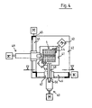
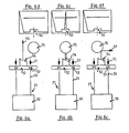
- FIGS. 4 and 5 Another configuration of the device is shown in FIGS. 4 and 5.
- the probes 27 are also arranged in different planes 38, 39, 40 here.
- a fuel element 1 to be tested is supported in a recess 41 in a base plate 42 and held by means of two clamping jaws 44 which can be controlled by a drive 43.
- three struts 45 extend in the vertical direction.
- Spindle drives 46 extend in different planes between the struts, so that a plurality of probes 27 can move into the spaces between the fuel rods 35 offset from one another by 90 °.
- the planes 38a, 39a, 40a of the probes offset by 90 ° have a different height level than the planes in order to enable simultaneous entry from different fuel element sides.
- a probe carrier 48 is fastened to the spindle nut 47, which in turn has a drive element 49 for the insertion movement of the probes into the spaces between the fuel rods.
Landscapes
- Physics & Mathematics (AREA)
- Engineering & Computer Science (AREA)
- Plasma & Fusion (AREA)
- General Engineering & Computer Science (AREA)
- High Energy & Nuclear Physics (AREA)
- General Physics & Mathematics (AREA)
- Monitoring And Testing Of Nuclear Reactors (AREA)
- Investigating Or Analyzing Materials By The Use Of Ultrasonic Waves (AREA)
- Length Measuring Devices Characterised By Use Of Acoustic Means (AREA)
Applications Claiming Priority (2)
| Application Number | Priority Date | Filing Date | Title |
|---|---|---|---|
| DE3632060 | 1986-09-20 | ||
| DE19863632060 DE3632060A1 (de) | 1986-09-20 | 1986-09-20 | Einrichtung zur inspektion von kernreaktor-brennstaeben |
Publications (3)
| Publication Number | Publication Date |
|---|---|
| EP0261563A2 EP0261563A2 (de) | 1988-03-30 |
| EP0261563A3 EP0261563A3 (en) | 1988-10-12 |
| EP0261563B1 true EP0261563B1 (de) | 1991-01-23 |
Family
ID=6310018
Family Applications (1)
| Application Number | Title | Priority Date | Filing Date |
|---|---|---|---|
| EP87113508A Expired - Lifetime EP0261563B1 (de) | 1986-09-20 | 1987-09-16 | Einrichtung zur Inspektion von Kernreaktor-Brennstäben |
Country Status (5)
| Country | Link |
|---|---|
| US (1) | US4847037A (enExample) |
| EP (1) | EP0261563B1 (enExample) |
| JP (1) | JPS63101798A (enExample) |
| KR (1) | KR880004495A (enExample) |
| DE (2) | DE3632060A1 (enExample) |
Families Citing this family (14)
| Publication number | Priority date | Publication date | Assignee | Title |
|---|---|---|---|---|
| US5066452A (en) * | 1989-07-24 | 1991-11-19 | The Babcock & Wilcox Company | Ultrasonic profilometry system for control rod wear |
| US5215706A (en) * | 1991-06-05 | 1993-06-01 | Siemens Power Corporation | Method and apparatus for ultrasonic testing of nuclear fuel rods employing an alignment guide |
| JPH06265685A (ja) * | 1993-03-12 | 1994-09-22 | Mitsubishi Nuclear Fuel Co Ltd | 燃料集合体の燃料棒位置測定方法及び装置 |
| US5661766A (en) * | 1995-02-14 | 1997-08-26 | Siemens Power Corporation | Nuclear fuel assembly bow and twist measurement apparatus |
| FR2754053B1 (fr) * | 1996-09-30 | 1999-04-16 | Framatome Sa | Procede et dispositif de mesure de deformation de tube guide |
| CN1355923A (zh) * | 1999-04-08 | 2002-06-26 | 电子研究所有限公司 | 用超声波清理有辐射性的核子燃料组件的装置和方法 |
| US6523412B1 (en) * | 2000-06-28 | 2003-02-25 | Framatome Anp Inc. | Apparatus and method for inspecting spring hold down bolts of an upper tie plate |
| US20060193422A1 (en) * | 2005-02-14 | 2006-08-31 | Davis Michael D | Fuel channel characterization method and device |
| US20060291608A1 (en) * | 2005-06-22 | 2006-12-28 | Davis Michael D | Fuel channel characterization method and device |
| RU2308715C1 (ru) * | 2006-05-22 | 2007-10-20 | Институт прикладной механики УрО РАН | Способ определения качества пропиточной жидкости канатов |
| KR101222012B1 (ko) * | 2011-07-08 | 2013-01-14 | 한전원자력연료 주식회사 | 핵연료집합체의 핵연료봉 외경 측정장치 |
| US20140255620A1 (en) * | 2013-03-06 | 2014-09-11 | Rolls-Royce Corporation | Sonic grain refinement of laser deposits |
| CN107369482B (zh) * | 2017-06-23 | 2019-04-16 | 西安交通大学 | 单根快堆组件热弯曲试验约束装置及热变形接触测量方法 |
| CZ307569B6 (cs) * | 2017-10-05 | 2018-12-12 | Centrum Výzkumu Řež S.R.O. | Metoda měření deformace palivového souboru pomocí ultrazvuku |
Family Cites Families (11)
| Publication number | Priority date | Publication date | Assignee | Title |
|---|---|---|---|---|
| DE2605962C2 (de) * | 1976-02-14 | 1982-05-06 | Brown Boveri Reaktor GmbH, 6800 Mannheim | Einrichtung zum Lokalisieren defekter Brennstabhüllrohre eines kompletten Brennelements |
| FR2493025B1 (fr) * | 1980-10-24 | 1986-04-18 | Framatome Sa | Procede et dispositif de detection d'elements combustibles defectueux dans un assemblage combustible pour reacteur nucleaire |
| DE3116978C2 (de) * | 1981-04-29 | 1986-06-12 | Brown Boveri Reaktor GmbH, 6800 Mannheim | Einrichtung zum Auffinden defekter Brennstabhüllrohre wassergekühlter Kernreaktoren |
| FR2517104B1 (fr) * | 1981-11-25 | 1987-07-24 | Commissariat Energie Atomique | Procede d'examen d'un assemblage combustible de reacteur nucleaire et machine d'examen pour la mise en oeuvre de ce procede |
| DE3149362C2 (de) * | 1981-12-12 | 1983-10-27 | Brown Boveri Reaktor GmbH, 6800 Mannheim | Verfahren zum Auffinden defekter Brennstabhüllrohre mit Hilfe von Ultraschall |
| DE3219938C2 (de) * | 1982-05-27 | 1987-02-19 | Brown Boveri Reaktor GmbH, 6800 Mannheim | Einrichtung zum Detektieren defekter Hüllrohre von Brennstäben aus kompletten Brennelementen wassergekühlter Kernreaktoren |
| DE3337084A1 (de) * | 1983-10-12 | 1985-04-25 | Brown Boveri Reaktor GmbH, 6800 Mannheim | Verfahren und einrichtung zum auffinden defekter brennstabhuellrohre wassergekuehlter kernreaktoren |
| DE3417742C2 (de) * | 1984-05-12 | 1987-04-09 | Steag Kernenergie Gmbh, 4300 Essen | Verfahren zum Zerlegen von Kernreaktor-Brennelementen und Vorrichtung zur Durchführung des Verfahrens |
| DE3419765C2 (de) * | 1984-05-26 | 1987-04-09 | Brown Boveri Reaktor GmbH, 6800 Mannheim | Einrichtung zur Inspektion von Kernreaktorbrennstäben |
| US4689193A (en) * | 1984-10-15 | 1987-08-25 | Exxon Nuclear Company Inc. | Mechanism for testing fuel tubes in nuclear fuel bundles |
| US4728483A (en) * | 1986-04-24 | 1988-03-01 | Westinghouse Electric Corp. | Apparatus for integrated fuel assembly inspection system |
-
1986
- 1986-09-20 DE DE19863632060 patent/DE3632060A1/de active Granted
-
1987
- 1987-09-16 DE DE8787113508T patent/DE3767628D1/de not_active Expired - Fee Related
- 1987-09-16 EP EP87113508A patent/EP0261563B1/de not_active Expired - Lifetime
- 1987-09-18 US US07/099,150 patent/US4847037A/en not_active Expired - Fee Related
- 1987-09-18 JP JP62234727A patent/JPS63101798A/ja active Pending
- 1987-09-19 KR KR870010425A patent/KR880004495A/ko not_active Withdrawn
Also Published As
| Publication number | Publication date |
|---|---|
| EP0261563A2 (de) | 1988-03-30 |
| EP0261563A3 (en) | 1988-10-12 |
| DE3632060C2 (enExample) | 1990-07-05 |
| JPS63101798A (ja) | 1988-05-06 |
| DE3767628D1 (de) | 1991-02-28 |
| US4847037A (en) | 1989-07-11 |
| DE3632060A1 (de) | 1988-05-05 |
| KR880004495A (ko) | 1988-06-04 |
Similar Documents
| Publication | Publication Date | Title |
|---|---|---|
| EP0261563B1 (de) | Einrichtung zur Inspektion von Kernreaktor-Brennstäben | |
| DE2633391C2 (de) | Anordnung zur Prüfung oder Ausrichtung rechtwinklig sich schneidender Achsen | |
| DE2248194A1 (de) | Messgeraet | |
| DE2659372B2 (de) | Vorrichtung zum Messen von drei Dimensionen eines Objektes | |
| EP1087407B1 (de) | Verfahren und Vorrichtung zum Inspizieren eines Kernreaktor-Brennelements | |
| EP0123835B1 (de) | Messarm einer Mehrkoordinaten-Messmaschine | |
| EP0095553A1 (de) | Einrichtung zur Inspektion von Brennelementen insbesondere zum Detektieren defekter Brennstäbe aus kompletten Brennelementen wassergekühlter Kernreaktoren | |
| DE69402159T2 (de) | Vorrichtung und Verfahren zum Überprüfen der Führungselemente eines Führungsrohrs in den oberen Einbauten eines Druckwasserkernreaktors | |
| DE2434467A1 (de) | In unterschiedliche richtungen verfahrbares pruefsystem, das bestimmte pruefrichtungen erfordert, fuer insbesondere nicht oder nur schwer zugaengliche stellen von druckbehaelterwaenden | |
| EP0577965A1 (de) | Verfahren zur Längs-, Quer- und Schrägfehlerprüfung mittels Ultraschall von Werkstücken nach dem Impuls-Echo-Verfahren | |
| DE102004033600B4 (de) | Verfahren und Messanordnung zur Bestimmung der Topografie einer Oberfläche und Kalibriereinrichtung zur Kalibrierung einer derartigen Messanordnung | |
| DE3107372A1 (de) | "brennelementenkastenmessmaschine" | |
| DE3304358C2 (de) | Verfahren zum Anstellen eines Schrägwälzlagers | |
| DE2239553B2 (de) | Zug- und/oder druckpruefmaschine | |
| DE3542200C2 (enExample) | ||
| EP0333009A1 (de) | Koordinatenmessmaschine | |
| EP0163935B1 (de) | Einrichtung zur Inspektion von Kernreaktorbrennstäben | |
| DE69006881T2 (de) | Verfahren und Vorrichtung zur Dimensions- und Geometrieüberprüfung von Führungs- und Positionierungselementen in den oberen Einbauten eines Druckwasser-Kernreaktors. | |
| DE2824629A1 (de) | Kalibriervorrichtung fuer ultraschall-inspektionsgeraete | |
| DE69403249T2 (de) | Verfahren und Vorrichtung zur Messung der Brennstabpositionen | |
| DE3632061C2 (enExample) | ||
| DE3515685A1 (de) | Pinole fuer koordinaten-messmaschine | |
| DE102006024579B4 (de) | Vorrichtung zur Bestimmung der Position eines entlang mindestens einer Verschieberichtung bewegbaren Objektes | |
| DE9318628U1 (de) | Kleinwasserphantom zur Überwachung von Teletherapiegeräten | |
| DE3532703A1 (de) | Verfahren und vorrichtung zum messen des innen- und/oder aussendurchmessers von werkstuecken |
Legal Events
| Date | Code | Title | Description |
|---|---|---|---|
| PUAI | Public reference made under article 153(3) epc to a published international application that has entered the european phase |
Free format text: ORIGINAL CODE: 0009012 |
|
| AK | Designated contracting states |
Kind code of ref document: A2 Designated state(s): BE CH DE ES FR IT LI NL SE |
|
| PUAL | Search report despatched |
Free format text: ORIGINAL CODE: 0009013 |
|
| AK | Designated contracting states |
Kind code of ref document: A3 Designated state(s): BE CH DE ES FR IT LI NL SE |
|
| RAP1 | Party data changed (applicant data changed or rights of an application transferred) |
Owner name: ABB REAKTOR GMBH |
|
| 17P | Request for examination filed |
Effective date: 19881209 |
|
| 17Q | First examination report despatched |
Effective date: 19900709 |
|
| GRAA | (expected) grant |
Free format text: ORIGINAL CODE: 0009210 |
|
| AK | Designated contracting states |
Kind code of ref document: B1 Designated state(s): BE CH DE ES FR IT LI NL SE |
|
| ITF | It: translation for a ep patent filed | ||
| ET | Fr: translation filed | ||
| REF | Corresponds to: |
Ref document number: 3767628 Country of ref document: DE Date of ref document: 19910228 |
|
| PG25 | Lapsed in a contracting state [announced via postgrant information from national office to epo] |
Ref country code: ES Free format text: LAPSE BECAUSE OF FAILURE TO SUBMIT A TRANSLATION OF THE DESCRIPTION OR TO PAY THE FEE WITHIN THE PRESCRIBED TIME-LIMIT Effective date: 19910504 |
|
| PGFP | Annual fee paid to national office [announced via postgrant information from national office to epo] |
Ref country code: FR Payment date: 19910628 Year of fee payment: 5 |
|
| PGFP | Annual fee paid to national office [announced via postgrant information from national office to epo] |
Ref country code: CH Payment date: 19910701 Year of fee payment: 5 |
|
| PGFP | Annual fee paid to national office [announced via postgrant information from national office to epo] |
Ref country code: SE Payment date: 19910704 Year of fee payment: 5 |
|
| PGFP | Annual fee paid to national office [announced via postgrant information from national office to epo] |
Ref country code: BE Payment date: 19910719 Year of fee payment: 5 |
|
| PGFP | Annual fee paid to national office [announced via postgrant information from national office to epo] |
Ref country code: NL Payment date: 19910930 Year of fee payment: 5 |
|
| PLBE | No opposition filed within time limit |
Free format text: ORIGINAL CODE: 0009261 |
|
| STAA | Information on the status of an ep patent application or granted ep patent |
Free format text: STATUS: NO OPPOSITION FILED WITHIN TIME LIMIT |
|
| 26N | No opposition filed | ||
| PG25 | Lapsed in a contracting state [announced via postgrant information from national office to epo] |
Ref country code: DE Effective date: 19920602 |
|
| PG25 | Lapsed in a contracting state [announced via postgrant information from national office to epo] |
Ref country code: SE Effective date: 19920917 |
|
| PG25 | Lapsed in a contracting state [announced via postgrant information from national office to epo] |
Ref country code: LI Effective date: 19920930 Ref country code: CH Effective date: 19920930 Ref country code: BE Effective date: 19920930 |
|
| BERE | Be: lapsed |
Owner name: ABB REAKTOR G.M.B.H. Effective date: 19920930 |
|
| PG25 | Lapsed in a contracting state [announced via postgrant information from national office to epo] |
Ref country code: NL Effective date: 19930401 |
|
| NLV4 | Nl: lapsed or anulled due to non-payment of the annual fee | ||
| PG25 | Lapsed in a contracting state [announced via postgrant information from national office to epo] |
Ref country code: FR Effective date: 19930528 |
|
| REG | Reference to a national code |
Ref country code: CH Ref legal event code: PL |
|
| REG | Reference to a national code |
Ref country code: FR Ref legal event code: ST |
|
| EUG | Se: european patent has lapsed |
Ref document number: 87113508.3 Effective date: 19930406 |
|
| PG25 | Lapsed in a contracting state [announced via postgrant information from national office to epo] |
Ref country code: IT Free format text: LAPSE BECAUSE OF NON-PAYMENT OF DUE FEES Effective date: 20050916 |