EP0260830B1 - Magnetic marker having switching section for use in electronic article surveillance systems - Google Patents
Magnetic marker having switching section for use in electronic article surveillance systems Download PDFInfo
- Publication number
- EP0260830B1 EP0260830B1 EP87307554A EP87307554A EP0260830B1 EP 0260830 B1 EP0260830 B1 EP 0260830B1 EP 87307554 A EP87307554 A EP 87307554A EP 87307554 A EP87307554 A EP 87307554A EP 0260830 B1 EP0260830 B1 EP 0260830B1
- Authority
- EP
- European Patent Office
- Prior art keywords
- marker
- piece
- switching
- switching section
- switching sections
- Prior art date
- Legal status (The legal status is an assumption and is not a legal conclusion. Google has not performed a legal analysis and makes no representation as to the accuracy of the status listed.)
- Expired - Lifetime
Links
Images


Classifications
-
- G—PHYSICS
- G08—SIGNALLING
- G08B—SIGNALLING SYSTEMS, e.g. PERSONAL CALLING SYSTEMS; ORDER TELEGRAPHS; ALARM SYSTEMS
- G08B13/00—Burglar, theft or intruder alarms
- G08B13/22—Electrical actuation
- G08B13/24—Electrical actuation by interference with electromagnetic field distribution
-
- G—PHYSICS
- G08—SIGNALLING
- G08B—SIGNALLING SYSTEMS, e.g. PERSONAL CALLING SYSTEMS; ORDER TELEGRAPHS; ALARM SYSTEMS
- G08B13/00—Burglar, theft or intruder alarms
- G08B13/22—Electrical actuation
- G08B13/24—Electrical actuation by interference with electromagnetic field distribution
- G08B13/2402—Electronic Article Surveillance [EAS], i.e. systems using tags for detecting removal of a tagged item from a secure area, e.g. tags for detecting shoplifting
- G08B13/2405—Electronic Article Surveillance [EAS], i.e. systems using tags for detecting removal of a tagged item from a secure area, e.g. tags for detecting shoplifting characterised by the tag technology used
- G08B13/2408—Electronic Article Surveillance [EAS], i.e. systems using tags for detecting removal of a tagged item from a secure area, e.g. tags for detecting shoplifting characterised by the tag technology used using ferromagnetic tags
- G08B13/2411—Tag deactivation
-
- G—PHYSICS
- G08—SIGNALLING
- G08B—SIGNALLING SYSTEMS, e.g. PERSONAL CALLING SYSTEMS; ORDER TELEGRAPHS; ALARM SYSTEMS
- G08B13/00—Burglar, theft or intruder alarms
- G08B13/22—Electrical actuation
- G08B13/24—Electrical actuation by interference with electromagnetic field distribution
- G08B13/2402—Electronic Article Surveillance [EAS], i.e. systems using tags for detecting removal of a tagged item from a secure area, e.g. tags for detecting shoplifting
- G08B13/2428—Tag details
- G08B13/2437—Tag layered structure, processes for making layered tags
- G08B13/2442—Tag materials and material properties thereof, e.g. magnetic material details
-
- Y—GENERAL TAGGING OF NEW TECHNOLOGICAL DEVELOPMENTS; GENERAL TAGGING OF CROSS-SECTIONAL TECHNOLOGIES SPANNING OVER SEVERAL SECTIONS OF THE IPC; TECHNICAL SUBJECTS COVERED BY FORMER USPC CROSS-REFERENCE ART COLLECTIONS [XRACs] AND DIGESTS
- Y10—TECHNICAL SUBJECTS COVERED BY FORMER USPC
- Y10S—TECHNICAL SUBJECTS COVERED BY FORMER USPC CROSS-REFERENCE ART COLLECTIONS [XRACs] AND DIGESTS
- Y10S428/00—Stock material or miscellaneous articles
- Y10S428/922—Static electricity metal bleed-off metallic stock
- Y10S428/9265—Special properties
- Y10S428/928—Magnetic property
Definitions
- This invention relates to electronic article surveillance (EAS) systems and markers used therein, and in particular, to such markers in which a piece of magnetic material utilized in the marker is interrogated by an alternating magnetic field and produces harmonics of the field which are detected to indicate the presence of the marker.
- EAS electronic article surveillance
- U.S. Patent No. 4,075,618 discloses that a marker capable of generating very high order harmonics, thereby being operative in a system such as described in the '449 patent, could be made by adding flux collectors to a short strip of high permeability material which is insufficiently long to meet the definition of an "open-strip".
- Picard also suggests that polar extensions may be provided to increase the sensitivity, while Fearon '945 suggests the use of pole piece coupons to collect flux.
- EAS systems in which the markers of the present invention are particularly useful typically produce within the interrogation zone fields in a variety of directions.
- such differently directed fields may be produced by providing currents in coils on opposite sides of the interrogation zone which are alternately in-phase and out-of-phase.
- the resulting aiding and opposing fields at any given location may be appreciably weaker in one direction than another.
- a given marker may be unacceptable if reliably detectable only when oriented in the direction associated with the strongest fields produced by the EAS system.
- a commercially viable marker would have a sensitivity so as to be reliably detectable regardless of how it is oriented in the zone, however, in a practical sense, it is not necessary to detect markers in each and every orientation and/or location in the zone.
- Typical EAS systems originally designed to be used with elongated "open strip” type markers are the Model WH-1000 and 1200 systems, marketed by Minnesota Mining and Manufacturing Company.
- such systems typically produce within the interrogation zones magnetic fields alternating at 10 kHz, and having minimum intensities at the center of the zone of approximately 96 A/m when the fields generated in coils on opposite sides of the zone are in an opposing configuration and of approximately 192 A/m when in an aiding configuration.
- the receiver portions of such systems process signals from receiver coils positioned within panels adjacent to the interrogation zone, and activate an alarm circuit in the event signals corresponding to very high order harmonics of the applied field are detected.
- test apparatus which generates fields alternating at a predetermined frequency and has controllable strength comparable to those encountered in such EAS systems.
- the test apparatus should detect signals in accordance with the harmonic characteristics relied upon in such systems and provide sensitivity values, based on a standard marker to ensure valid comparative results.
- Such a test apparatus is preferably calibrated against a present commercially available marker such as a type WH 0117 Whispertape brand detection strip manufactured by Minnesota Mining and Manufacturing Company, which is formed of an amorphous metal 6.7 cm long, 1.6 mm wide and 0.02 mm thick and having the following nominal composition (at %): Co:69%; Fe:4.1%; Ni:3.4%; Mo:1.5%; Si:10%; and B:12%.
- a marker is inserted parallel with the fieldof the test apparatus and the gain is adjusted to indicate a standardized sensitivity value of 1.0 at a 10 KHz field of 96 A/m that being the minimum field strength at which such a marker would be expected to be reliably detected.
- a sensitivity of 4.8 was observed when the amorphous marker was similarly aligned.
- very high order harmonics may be generated by markers which are made of magnetic materials similar to those used in the past, but which are much smaller than heretofore known and are not formed of elongated strips. Rather, it has been found that very high order harmonics are readily generated in a high permeability material having a square or rectangular, i.e., postage-stamp, shape, which has at least one very short, narrow cross-sectional center section formed of a high permeability, low coercive force material and which has flux collectors proximate to each end of the center section.
- the center section thus functions as a magnetic switching section to generate the very high order harmonic response so long as the flux collectors are sufficiently wide to collect and concentrate a significant amount of flux within the switching section.
- the effective flux density is increased so that the magnetization in that section is very rapidly reversed upon each reversal of the applied field and very high order harmonics are generated at a given applied field intensity just as though an elongated strip were present. It has been found that the signals produced by such markers, while containing very high order harmonics upon which detection can be reliably based, also contain various other isolatable characteristics making the markers useful in other systems in which harmonics per se may not be isolated.
- the switching sections and flux collectors making up the magnetic construction have overall dimensions in which the length and width are not greater than 3.2 cm, and are preferably less than 2.5 cm.
- the switching section is formed of a piece of low coercive force, high permeability material having a minimum width the cross-sectional area of which is in the range of 0.003-0.03 mm2.
- the length of the switching section normal to its minimum width is not greater than 20 times that width and is less than 2.0 cm, the terminal ends of each switching section being further defined by points at which the width (parallel to the minimum width) is no longer less than five times the minimum width.
- Each of the flux collectors is formed of co-planar sections of a sheet-like material of low coercive force, high permeability material having a maximum width parallel to the width of the switching section which is at least ten times the minimum width of the switching section.
- Such a marker is still basically responsive in only one direction, and may be only marginally acceptable, as relative sensitivities of only about 0.4 result when measured at the weakest field of 96 A/m. However, values in excess of 1.0 are observed at higher intensities, such that the marker would be detected under all but the least favorable conditions.
- the marker of the present invention comprises at least two switching sections such as described above, the lengths of which extend in substantially different directions. Furthermore each switching section preferably shares at least one common flux collector.
- Such an embodiment is particularly desirably constructed of a substantially square, sheet-like piece of low coercive force, high permeability material having a portion removed from the interior thereof to result in at least two narrow regions between the removed portion and two adjacent outer edges of the piece, which narrow regions define two switching sections extending normal to each other.
- the removed portion is circular and is centered within the square piece to result in four switching sections proximate the mid point of each side of the piece, with the four corner portions providing flux collectors for two pairs of switching sections, each pair being at right angles to each other.
- a marker will then be detectable regardless of its orientation, as when one side of the marker is oriented in the direction of a weak field, so as to produce only a marginally acceptable signal, another side may be oriented parallel to a stronger field and will thereupon result in an adequately detectable signal.
- a marker such as described in the above embodiments is conveniently made dual-status, i.e., reversibly deactivatable and reactivatable by including a piece of remanently magnetizable material adjacent each of the switching sections, which piece when magnetized provides fields which bias the magnetization of the switching section to alter the response of the marker resulting from the alternating magnetic field encountered in the interrogation zones.
- one embodiment of the marker of the present invention comprises a sheet of low coercive force, high permeability material, such as permalloy.
- the sheet is cut to have at least one center or switching section of reduced cross-sectional area and a flux collector adjacent each opposite end of the switching section.
- the marker 10 has a switching section 12 and triangular shaped flux collectors 14 and 16.
- the marker is preferably cut from a sheet of permalloy, 0.015 mm thick, such that the overall width and length of the piece is 2.5 ⁇ 2.5 cm respectively.
- the switching section 12 is symmetrically centered between the flux collectors 14 and 16, and has a width of 0.76 mm and a length of 4.8 mm.
- the thus cut sheet is desirably adhered via a pressure sensitive adhesive to a backing layer 18 such as paper, stiff plastic sheeting, etc.
- Markers according to the present invention are also useful in systems operating over a range of frequencies. While in the tests noted above, a frequency of 10 kHz was used, as that frequency corresponds to the frequency used in the 3M Model WH-1000 and 1200 systems, equivalent performance has been observed when the markers are tested at other frequencies.
- the cross-sectional area of the switching section of the marker of the present invention is very important to the resultant sensitivity.
- a series of tests were conducted with markers constructed from 0.015 mm thick permalloy in which the overall dimensions of the flux collectors and the length of the switching sections were the same as that described above with reference to Figure 1, and in which the width of the switching section was variously 0.13, 0.38, 0.76 and 1.4 mm, respectively (i.e., the cross-sectional area of the switching section thus being variously 0.0020, 0.0058, 0.012 and 0.021 mm2, respectively).
- FIG. 2A Another embodiment of the marker similar to that discussed above with respect to Figure 1, is shown in the top view of Figure 2A.
- the marker 20 shown in that Figure is similarly preferably constructed from a sheet of permalloy, fabricated to have a center switching section 24 and flux collectors 26 and 28 at each end, adhered to a backing sheet 32.
- the switching section 24 was formed by punching semicircular areas out of the sheet such that the switching section 24 is formed in the center region between the semicircular cut-outs.
- the switching section 24 is readily defined, in the embodiment of Figure 2A, there is a gradual transition between the switching section 24 and the adjacent flux collectors 26 and 28.
- the limits of the switching section 24 as shown in the enlarged view of Figure 2B as having a minimum width (W min ) 34 and a length (L) 38 normal to the minimum width which is not greater than twenty times the minimum width.
- the terminal ends of the length L are at lines 36 at which the width is no longer less than five times the minimum width.
- the switching sections are conveniently produced by stamping semicircular notches from opposite sides, leaving a 0.76 mm wide switching section therebetween.
- a second element 30 of a higher coercive force, remanently magnetizable material such as vicalloy, carbon steel, or the like is also shown as a part of the marker 20 of Figure 2A, the addition of such a piece making the marker dual-status.
- a material when magnetized in the region of the switching section, provides an external magnetic field which biases the adjacent switching section to either keep the magnetization therein from reversing when in an alternating interrogation field, or of at least altering the response then produced. In either case, readily distinguishably different signals are produced, depending upon whether the second element 30 is magnetized or demagnetized.
- the markers 10 and 20 shown in Figures 1, 2A and 2B desirably include non-magnetic backing layers 18 and 32 respectively.
- Such layers may be pieces of stiff paper, cardboard, plastic sheet, etc., and may be on either or both sides of the magnetic sheet as desired. The layers thus protect the magnetic sheets from deformation, bending, flexing and the like, which could adversely affect the magnetic response, conceals the magnetic material and provides printable surfaces on which user information may be added, etc.
- pressure sensitive adhesive layers, low adhesion carrier liners, printable top layers, and the like may also be included.
- the markers discussed above with respect to Figures 1, 2A and 2B exhibit maximum sensitivity in one direction only, i.e., the markers must be oriented with respect to fields present in the interrogation zone such that the flux collectors subtend as many lines of flux as possible. To ensure that such markers are detected regardless of orientation, it is thus desirable to provide in the zone fields in three orthogonal directions. Such constraints on the field producing portion of the system clearly add complexity and cost to the systems.
- markers are provided which exhibit sensitivity in at least two directions, thereby allowing the field producing apparatus to be simplified such that fields need only be present in two orthogonal directions.
- One such multi-directionally responsive marker 40 is shown in Figure 3 to comprise a square sheet of high permeability material such as permalloy or the like, in which a circular center portion 42 has been removed, having four switching sections 44, 44 ⁇ , 44 ⁇ and 44 ⁇ at the mid point of each straight side. The corners of the square thus form flux collectors for the switching sections, each corner acting as a flux collector for two switching sections extending therefrom.
- Such a marker formed of 0.015 mm thick permalloy 2.5 cm long on each side, and having a circle removed from the center, thereby forming 0.76 mm wide switching sections, was found to have an equivalent sensitivity of 0.34 when measured as described above at the minimum field intensity, and positioned such that any one of the straight sides was aligned with the field in the solenoid. At field intensities of 192 A/m and 288 A/m respectively, sensitivities of 1.1 and 1.6 were observed.
- Multi-directional markers may analogously be provided from a variety of other two dimensional shapes, particularly of regular polygons, thus minimizing material waste.
- Another such multi-directionally responsive marker 46 is shown in Figure 4 to be formed of a triangle of high permeability material such as described above, again in which there is removed a circular center portion 50, leaving narrow switching sections 52, 52 ⁇ , and 52 ⁇ at the mid point of each side.
- the marker has further been made to be dual status by including sections 54 of remanently magnetizable material overlying each switching section.
- magnetization of the sections 54 result in localized fields which bias the high permeability material in the adjacent switching sections 52, 52 ⁇ and 52 ⁇ , and alters the signal resulting when the marker is exposed to alternating fields in an interrogation zone.
- a marker with the shape of an equilateral triangle constructed from 0.015 mm thick permalloy 2.5 cm on each side and having a circle removed from the center, leaving 0.58 mm wide switching sections along each side was found to exhibit marginally acceptable sensitivity when any of the sides were aligned with a minimum 96 A/m field in the test appartus described above.
- a square marker such as shown in Figure 3 may be conveniently formed from a large sheet of permalloy, which is then cut and/or stamped to remove the circular center areas and to separate the individual square pieces.
- the switching sections are typically in the range of 0.76 mm wide, the circular areas to be removed from adjacent sections are thus 1.52 mm apart. Accordingly, the location of the cut between the removed circular portions must be very accurately controlled to ensure that the width of each switching section is 0.76 mm, and not, for example, 0 64 mm on one side and 0.89 mm on the other side of the cut. While such variability would result in usable markers, the variation in sensitivities from marker to marker precludes optimization of the marker with a given system.
- each switching section 56 along each edge of the markers 58 is defined as the width of the material remaining between a large punched-out center hole 60 and smaller notches located approximately halfway along the edge.
- a sheet of permalloy is desirably provided with a pattern of alternating large and small holes 60 and 62 which extends both along and across the web. The size and location of the punched holes 60 and 62 are determined by a punch and die operation or by etching.
- the 0.76 mm wide switching sections 56 are thus precisely defined independently of the precise location of the cut line between the markers, and the markers may be subsequently separated from each other by cutting along lines extending through the small holes, resulting in the notches along each side, both across and down the web. In this manner, the markers may be manufactured in large quantities by roller dies and the like without need for precise alignment and positioning of the cutting shears or dies.
- Such mass-produced, multi-directionally responsive markers are desirably made by a series of punching or etching, slitting, and laminating operations.
- a web 84 of high permeability material such as a 0.015 mm thick sheet of permalloy is provided which is sufficiently wide to allow a plurality of markers positioned side by side to be cut therefrom, the number of markers thus formed in the down-web direction being only limited by the length of the web.
- a web 15 cm wide may be utilized, thus allowing six markers to be formed side-by-side.
- the sheet is then punched with a first set of repetitive patterns 86, each pattern consisting of three adjacent holes extending normal to lines 88 extending parallel to the length of the web along which the sheet will be subsequently cut to form strips 89 of a series of individual markers.
- the sheet is also punched with a second set of repetitive patterns 90 of three adjacent holes extending normal to lines 92 extending cross-web along which the strips 89 will be cut to separate the individual markers.
- the lines 88 and 92 will thus be 2.54 cm apart, and each of three holes making up the patterns 86 and 90 will be 3.2 mm diameter, with a 0.76 mm space between adjacent holes.
- the web 84 is subsequently passed through a punch and die to remove larger circular areas 94, the areas being approximately centered within the inner facing four holes of each of the markers being formed.
- the widths of the respective switching sections are defined by the spacing between the adjacent holes within the sets of three holes, it will be evident that the precise location of the larger, centrally located holes is much less critical.
- the web consists of a strain-sensitive material such as permalloy
- a further improvement may be affected by angling each set of three holes 86 and 90 with respect to the cut lines 88 and 92 such that the width of the switching sections is at an angle such as 45° with respect to the cut lines. Accordingly, such mechanical working and stress induced signal degradation as may occur as the strips 89 are wound in a roll and dispensed will be minimized.
- one side of the thus punched and annealed permalloy web 84 is next preferably laminated to a 0.05 mm thick pressure sensitive adhesive layer 96, the opposite side of which is covered by a 0.13 mm thick low adhesion release liner 98, which may be subsequently removed, allowing the markers to be affixed to articles via the adhesive layer 96.
- the other side of the punched metal web 84 is laminated to a 0.10 mm thick printable cover layer 100 via a 0.05 mm thick pressure sensitive layer 102.
- This laminate is then severed along the lines 88, thus forming the strips 89 along the length of the web, and is partially slit along the line 92, leaving unsevered the release liner 98, to thereby support the strip.
- the strips may then be wound into rolls for subsequent use in label guns and the like, wherein individual markers are peeled away from the release liner just prior to being adhered to articles to be protected.
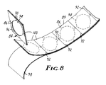
- FIG 8. Further details of one strip 89 after the final laminate is formed are shown in Figure 8.
- the top surface of the punched metal strip 89 is laminated to the printable surface layer 100 via the pressure sensitive adhesive layer 102.
- the bottom of the strip 89 has adjacent thereto the layer of pressure sensitive adhesive 96, which in turn is covered by the low adhesion carrier layer 98. All of the layers except for the carrier layer 98 are cut along the lines 92, thus allowing the strip to be dispersed in roll form, and individual markers peeled away from the carrier layer 98 as the strip is unwound.
- a multi-directionally responsive marker of the present invention comprises a switching section having more than two flux collectors associated therewith.
- a marker 66 may comprise a sheet 68 of high permeability material laminated to a non-magnetic backing sheet 70.
- the high permeability sheet 68 is cut into an "iron-cross" configuration, such that there is a switching section 72 at the center, and four flux collectors 74, 76, 78 and 80 magnetically coupled to the switching section.
- One pair of flux collectors 74 and 78 thus collects flux along a first direction, while the other pair of collectors 76 and 80 collects flux at 90° from the first direction, thus providing the desired multi-directional response.
- the marker shown in Figure 9 may further be made dual status by including a piece of remanently magnetizable material overlying the switching section, which when magnetized, alters the response produced by the high permeability section.
- markers of the present invention were tested in the test apparatus described above, but wherein the solenoid was energized at 10,000 Hz, 1000 Hz and 100 Hz, and the receiver circuits were adjusted to process the same, very high order harmonics. Measurements were made at field intensities of 80, 160 & 240 A/m. In each case the sensitivity was compared to that of an amorphous strip, 6.67 cm long, 1.6 mm wide and 0.020 mm thick. The following relative sensitivities were measured:
- the sensitivity of the square marker of the present invention at a field intensity of about 160 A/m is about the same as that observed from the amorphous strip when measured at a field intensity of 80 A/m. While the sensitivity of the square marker in any given direction is thus less than that of an elongated strip, the square marker responds to fields in at least two directions, and is thus desirably used in systems in which fields in fewer directions are present, or in which fields in one or more directions are stronger than that produced in other directions. It will also be appreciated that at lower frequencies the relative detected signal strengths were observed to significantly decrease, thus demonstrating the desirability of operating at higher frequencies. Alternatively, the receiver/detection circuits are desirably made more sensitive.
- the switching sections may be formed of separate pieces of high permeability material which are connected to separate flux collection pieces so as to provide a low reluctance path therebetween.
- the switching sections may be of any cross-sectional shape, and may thus be foamed from sheet stock, wires, etc.
- flux collectors are within the scope of the present invention.
- the overall configuration and the removed portion may be of any shape, so long as the dimensions of the switching sections and flux collectors are within the limits defined herein.
Landscapes
- Physics & Mathematics (AREA)
- Electromagnetism (AREA)
- General Physics & Mathematics (AREA)
- Engineering & Computer Science (AREA)
- Automation & Control Theory (AREA)
- Computer Security & Cryptography (AREA)
- Burglar Alarm Systems (AREA)
Applications Claiming Priority (2)
| Application Number | Priority Date | Filing Date | Title |
|---|---|---|---|
| US909340 | 1986-09-19 | ||
| US06/909,340 US4710754A (en) | 1986-09-19 | 1986-09-19 | Magnetic marker having switching section for use in electronic article surveillance systems |
Publications (3)
| Publication Number | Publication Date |
|---|---|
| EP0260830A2 EP0260830A2 (en) | 1988-03-23 |
| EP0260830A3 EP0260830A3 (en) | 1989-07-19 |
| EP0260830B1 true EP0260830B1 (en) | 1992-08-12 |
Family
ID=25427064
Family Applications (1)
| Application Number | Title | Priority Date | Filing Date |
|---|---|---|---|
| EP87307554A Expired - Lifetime EP0260830B1 (en) | 1986-09-19 | 1987-08-26 | Magnetic marker having switching section for use in electronic article surveillance systems |
Country Status (11)
| Country | Link |
|---|---|
| US (1) | US4710754A (da) |
| EP (1) | EP0260830B1 (da) |
| JP (1) | JP2994645B2 (da) |
| KR (1) | KR960002142B1 (da) |
| AU (1) | AU602151B2 (da) |
| CA (1) | CA1276255C (da) |
| DE (1) | DE3781073T2 (da) |
| DK (1) | DK170481B1 (da) |
| ES (1) | ES2033860T3 (da) |
| MX (1) | MX160028A (da) |
| ZA (1) | ZA877052B (da) |
Families Citing this family (59)
| Publication number | Priority date | Publication date | Assignee | Title |
|---|---|---|---|---|
| US4746908A (en) * | 1986-09-19 | 1988-05-24 | Minnesota Mining And Manufacturing Company | Dual-status, magnetically imagable article surveillance marker |
| US4829288A (en) * | 1987-11-30 | 1989-05-09 | Minnesota Mining And Manufacturing Company | Economic, multi-directionally responsive marker for use in electronic article surveillance systems |
| US4849736A (en) * | 1987-12-11 | 1989-07-18 | Pitney Bowes Inc. | Magnetic marker having a rectangular configuration for electronic article surveillance |
| US4884063A (en) * | 1988-02-01 | 1989-11-28 | Minnesota Mining And Manufacturing Company | Dual status magnetic marker having magnetically biasable flux collectors for use in electronic article surveillance systems |
| US4825197A (en) * | 1988-02-01 | 1989-04-25 | Minnesota Mining And Manufacturing Company | Dual status magnetic marker having magnetically biasable flux collectors for us in electronic article surveillance systems |
| US4857891A (en) * | 1988-04-29 | 1989-08-15 | Minnesota Mining And Manufacturing Company | Random-filament, multi-directionally responsive marker for use in electronic article surveillance systems |
| US5003291A (en) * | 1988-12-27 | 1991-03-26 | Strom Olsen John O | Ferromagnetic fibers having use in electronical article surveillance and method of making same |
| US5015992A (en) * | 1989-06-29 | 1991-05-14 | Pitney Bowes Inc. | Cobalt-niobium amorphous ferromagnetic alloys |
| US5015993A (en) * | 1989-06-29 | 1991-05-14 | Pitney Bowes Inc. | Ferromagnetic alloys with high nickel content and high permeability |
| US4967185A (en) * | 1989-08-08 | 1990-10-30 | Minnesota Mining And Manufacturing Company | Multi-directionally responsive, dual-status, magnetic article surveillance marker having continuous keeper |
| US5151843A (en) * | 1989-12-08 | 1992-09-29 | Minnesota Mining And Manufacturing Company | Sensitizer for ferromagnetic markers used with electromagnetic article surveillance systems |
| GB9022318D0 (en) * | 1990-10-15 | 1990-11-28 | Esselte Meto Int Gmbh | Magnetic property modification |
| US5121106A (en) * | 1990-12-31 | 1992-06-09 | Pitney Bowes Inc. | Electronic article surveillance markers with diagonal deactivation elements |
| US5253821A (en) * | 1992-03-02 | 1993-10-19 | Minnesota Mining And Manufacturing Company | Security magnetic tape cartridge for use in electronic article surveillance systems |
| US5347508A (en) * | 1992-04-22 | 1994-09-13 | Minnesota Mining And Manufacturing Company | Optical information storage disk for use with electronic article surveillance systems |
| US5580664A (en) * | 1992-12-23 | 1996-12-03 | Minnesota Mining And Manufacturing Company | Dual status thin-film eas marker having multiple magnetic layers |
| US5432499A (en) * | 1993-05-27 | 1995-07-11 | Minnesota Mining And Manufacturing Company | Collector type article surveillance marker with continuous keeper |
| AU667431B2 (en) * | 1993-06-11 | 1996-03-21 | Sensormatic Electronics Corporation | Multidirectional surveillance marker |
| US5405702A (en) * | 1993-12-30 | 1995-04-11 | Minnesota Mining And Manufacturing Company | Method for manufacturing a thin-film EAS and marker |
| DE4436974B4 (de) * | 1994-10-15 | 2004-04-01 | Meto International Gmbh | Markierungselement zur Sicherung von Artikeln gegen Diebstahl |
| DE4440314A1 (de) * | 1994-11-11 | 1996-05-15 | Esselte Meto Int Gmbh | Markierungselement zur Sicherung von Artikeln gegen Diebstahl |
| US5519379A (en) * | 1995-04-10 | 1996-05-21 | Sensormatic Electronics Corporation | Multi-thread re-entrant marker with simultaneous switching |
| GB9605175D0 (en) * | 1996-03-12 | 1996-05-15 | Entertainment Uk Ltd | Improvements in or relating to securing apparatus |
| DE19650610A1 (de) * | 1996-12-06 | 1998-06-10 | Meto International Gmbh | Verfahren und Vorrichtung zur Herstellung von elektronischen Sicherungselementen |
| DE19711626A1 (de) * | 1997-03-20 | 1998-09-24 | Meto International Gmbh | Streifen zur Bereitstellung von Sicherungselementen für die elektronische Artikelsicherung |
| US5835016A (en) * | 1997-12-15 | 1998-11-10 | Sensormatic Electronics Corporation | Multi-thread re-entrant marker with transverse anisotropy flux concentrators |
| GB9800064D0 (en) * | 1998-01-05 | 1998-03-04 | Sentec Ltd | Uni-directional magnetic tag |
| US6023226A (en) * | 1998-01-29 | 2000-02-08 | Sensormatic Electronics Corporation | EAS marker with flux concentrators having magnetic anisotropy oriented transversely to length of active element |
| US6002335A (en) * | 1998-02-18 | 1999-12-14 | 3M Innovative Properties Company | Small magnet resensitizer apparatus for use with article surveillance systems |
| RU2144219C1 (ru) * | 1998-05-13 | 2000-01-10 | Попов Александр Федорович | Марка |
| US6121879A (en) * | 1998-12-23 | 2000-09-19 | Sensormatic Electronics Corporation | Deactivation element configuration for microwave-magnetic EAS marker |
| US6525661B2 (en) | 1999-02-26 | 2003-02-25 | 3M Innovative Properties Company | Electronic article surveillance markers for optically recorded media |
| US7458091B1 (en) | 2000-01-20 | 2008-11-25 | Sonic Solutions, A California Corporation | System, method and article of manufacture for a business layer component in a multimedia synchronization framework |
| US7448021B1 (en) | 2000-07-24 | 2008-11-04 | Sonic Solutions, A California Corporation | Software engine for combining video or audio content with programmatic content |
| US6453420B1 (en) | 1999-04-21 | 2002-09-17 | Research Investment Network, Inc. | System, method and article of manufacture for authorizing the use of electronic content utilizing a laser-centric medium |
| US6941383B1 (en) | 2000-01-20 | 2005-09-06 | Interactual Technologies, Inc. | System, method and article of manufacture for java/javascript component in a multimedia synchronization framework |
| US7178106B2 (en) * | 1999-04-21 | 2007-02-13 | Sonic Solutions, A California Corporation | Presentation of media content from multiple media sources |
| US6529949B1 (en) * | 2000-02-07 | 2003-03-04 | Interactual Technologies, Inc. | System, method and article of manufacture for remote unlocking of local content located on a client device |
| US6405203B1 (en) | 1999-04-21 | 2002-06-11 | Research Investment Network, Inc. | Method and program product for preventing unauthorized users from using the content of an electronic storage medium |
| US7346920B2 (en) * | 2000-07-07 | 2008-03-18 | Sonic Solutions, A California Corporation | System, method and article of manufacture for a common cross platform framework for development of DVD-Video content integrated with ROM content |
| US20050198574A1 (en) * | 1999-04-21 | 2005-09-08 | Interactual Technologies, Inc. | Storyboard |
| US20060193606A1 (en) * | 1999-04-21 | 2006-08-31 | Interactual Technologies, Inc. | Two navigation |
| US6665489B2 (en) | 1999-04-21 | 2003-12-16 | Research Investment Network, Inc. | System, method and article of manufacturing for authorizing the use of electronic content utilizing a laser-centric medium and a network server |
| US7188193B1 (en) | 2000-01-20 | 2007-03-06 | Sonic Solutions, A California Corporation | System, method and article of manufacture for a synchronizer component in a multimedia synchronization framework |
| US6769130B1 (en) * | 2000-01-20 | 2004-07-27 | Interactual Technologies, Inc. | System, method and article of manufacture for late synchronization during the execution of a multimedia event on a plurality of client computers |
| US20060041639A1 (en) * | 1999-04-21 | 2006-02-23 | Interactual Technologies, Inc. | Platform detection |
| US20050182828A1 (en) * | 1999-04-21 | 2005-08-18 | Interactual Technologies, Inc. | Platform specific execution |
| AU4359400A (en) * | 1999-04-21 | 2000-11-02 | Interactual Technologies, Inc. | System, method and article of manufacture for updating content stored on a portable storage medium |
| US6957220B2 (en) | 2000-11-07 | 2005-10-18 | Research Investment Networks, Inc. | System, method and article of manufacture for tracking and supporting the distribution of content electronically |
| US7392481B2 (en) * | 2001-07-02 | 2008-06-24 | Sonic Solutions, A California Corporation | Method and apparatus for providing content-owner control in a networked device |
| US20040220926A1 (en) * | 2000-01-03 | 2004-11-04 | Interactual Technologies, Inc., A California Cpr[P | Personalization services for entities from multiple sources |
| US20040220791A1 (en) * | 2000-01-03 | 2004-11-04 | Interactual Technologies, Inc. A California Corpor | Personalization services for entities from multiple sources |
| US20050251732A1 (en) * | 2000-01-20 | 2005-11-10 | Interactual Technologies, Inc. | System, method and article of manufacture for executing a multimedia event on a plurality of client computers using a synchronization host engine |
| US6275156B1 (en) * | 2000-02-07 | 2001-08-14 | Westvaco Corporation | EAS ready paperboard |
| US7689510B2 (en) * | 2000-09-07 | 2010-03-30 | Sonic Solutions | Methods and system for use in network management of content |
| US7191442B2 (en) * | 2000-10-30 | 2007-03-13 | Research Investment Network, Inc. | BCA writer serialization management |
| WO2006066052A2 (en) | 2004-12-16 | 2006-06-22 | Sonic Solutions | Methods and systems for use in network management of content |
| US7555715B2 (en) * | 2005-10-25 | 2009-06-30 | Sonic Solutions | Methods and systems for use in maintaining media data quality upon conversion to a different data format |
| JP7089347B2 (ja) * | 2016-07-20 | 2022-06-22 | 日東電工株式会社 | 粘着シート |
Family Cites Families (9)
| Publication number | Priority date | Publication date | Assignee | Title |
|---|---|---|---|---|
| FR763681A (fr) * | 1933-11-10 | 1934-05-04 | Procédé de repérage des objets par modification d'un champ magnétique | |
| US3790945A (en) * | 1968-03-22 | 1974-02-05 | Stoplifter Int Inc | Open-strip ferromagnetic marker and method and system for using same |
| US3747086A (en) * | 1968-03-22 | 1973-07-17 | Shoplifter International Inc | Deactivatable ferromagnetic marker for detection of objects having marker secured thereto and method and system of using same |
| US3665449A (en) * | 1969-07-11 | 1972-05-23 | Minnesota Mining & Mfg | Method and apparatus for detecting at a distance the status and identity of objects |
| US4075618A (en) * | 1976-07-15 | 1978-02-21 | Minnesota Mining And Manufacturing Company | Magnetic asymmetric antipilferage marker |
| US4074249A (en) * | 1977-02-04 | 1978-02-14 | Knogo Corporation | Magnetic detection means |
| US4249167A (en) * | 1979-06-05 | 1981-02-03 | Magnavox Government And Industrial Electronics Company | Apparatus and method for theft detection system having different frequencies |
| US4300183A (en) * | 1980-03-27 | 1981-11-10 | Richardson Robert H | Method and apparatus for generating alternating magnetic fields to produce harmonic signals from a metallic strip |
| CA1282398C (en) * | 1985-10-21 | 1991-04-02 | Donald J. Klocke | Synthesis of zeolites zsm-22 and zsm-23 |
-
1986
- 1986-09-19 US US06/909,340 patent/US4710754A/en not_active Expired - Lifetime
-
1987
- 1987-07-07 AU AU75304/87A patent/AU602151B2/en not_active Expired
- 1987-07-14 CA CA000541960A patent/CA1276255C/en not_active Expired - Lifetime
- 1987-08-26 ES ES198787307554T patent/ES2033860T3/es not_active Expired - Lifetime
- 1987-08-26 DE DE8787307554T patent/DE3781073T2/de not_active Expired - Lifetime
- 1987-08-26 EP EP87307554A patent/EP0260830B1/en not_active Expired - Lifetime
- 1987-08-31 JP JP62215551A patent/JP2994645B2/ja not_active Expired - Lifetime
- 1987-09-02 MX MX8085A patent/MX160028A/es unknown
- 1987-09-18 DK DK490687A patent/DK170481B1/da active
- 1987-09-18 ZA ZA877052A patent/ZA877052B/xx unknown
- 1987-09-18 KR KR1019870010396A patent/KR960002142B1/ko not_active Expired - Fee Related
Also Published As
| Publication number | Publication date |
|---|---|
| ES2033860T3 (es) | 1993-04-01 |
| DK170481B1 (da) | 1995-09-11 |
| AU602151B2 (en) | 1990-10-04 |
| EP0260830A3 (en) | 1989-07-19 |
| JP2994645B2 (ja) | 1999-12-27 |
| CA1276255C (en) | 1990-11-13 |
| DE3781073D1 (de) | 1992-09-17 |
| JPS6378293A (ja) | 1988-04-08 |
| AU7530487A (en) | 1988-03-24 |
| DK490687D0 (da) | 1987-09-18 |
| ZA877052B (en) | 1989-04-26 |
| EP0260830A2 (en) | 1988-03-23 |
| MX160028A (es) | 1989-11-09 |
| DE3781073T2 (de) | 1993-03-11 |
| US4710754A (en) | 1987-12-01 |
| KR880004329A (ko) | 1988-06-07 |
| KR960002142B1 (ko) | 1996-02-13 |
| DK490687A (da) | 1988-03-20 |
Similar Documents
| Publication | Publication Date | Title |
|---|---|---|
| EP0260830B1 (en) | Magnetic marker having switching section for use in electronic article surveillance systems | |
| CA1301879C (en) | Economic, multi-directionally responsive marker for use in electronic article surveillance systems | |
| EP0412721B1 (en) | Multi-directionally responsive, dual-status, magnetic article surveillance marker having a persistent state | |
| EP0340034B1 (en) | Random-filament, multi-directionally responsive marker for use in electronic article surveillance systems | |
| EP0260831B1 (en) | Dual-status, magnetically imagable article surveillance marker | |
| EP0170854B1 (en) | Theft detection apparatus and target and method of making same | |
| US4222517A (en) | Magnetic marker | |
| GB1581844A (en) | Antipilferage marker | |
| EP0737948B1 (en) | Multi-thread re-entrant marker with simultaneous switching | |
| CA2162999C (en) | Collector type article surveillance marker having a persistant state | |
| EP0327329B1 (en) | Dual status magnetic marker having magnetically biasable flux collectors for use in electronic article surveillance systems | |
| US5191315A (en) | Deactivatable electronic article surveillance markers using short semi-hard magnetic wires | |
| CA2057427C (en) | Electronic article surveillance markers with diagonal deactivation elements | |
| US4884063A (en) | Dual status magnetic marker having magnetically biasable flux collectors for use in electronic article surveillance systems | |
| GB2080075A (en) | Improved Magnetic Marker |
Legal Events
| Date | Code | Title | Description |
|---|---|---|---|
| PUAI | Public reference made under article 153(3) epc to a published international application that has entered the european phase |
Free format text: ORIGINAL CODE: 0009012 |
|
| AK | Designated contracting states |
Kind code of ref document: A2 Designated state(s): BE CH DE ES FR GB IT LI NL SE |
|
| PUAL | Search report despatched |
Free format text: ORIGINAL CODE: 0009013 |
|
| AK | Designated contracting states |
Kind code of ref document: A3 Designated state(s): BE CH DE ES FR GB IT LI NL SE |
|
| 17P | Request for examination filed |
Effective date: 19900102 |
|
| 17Q | First examination report despatched |
Effective date: 19911114 |
|
| GRAA | (expected) grant |
Free format text: ORIGINAL CODE: 0009210 |
|
| ITF | It: translation for a ep patent filed | ||
| AK | Designated contracting states |
Kind code of ref document: B1 Designated state(s): BE CH DE ES FR GB IT LI NL SE |
|
| REF | Corresponds to: |
Ref document number: 3781073 Country of ref document: DE Date of ref document: 19920917 |
|
| ET | Fr: translation filed | ||
| REG | Reference to a national code |
Ref country code: ES Ref legal event code: FG2A Ref document number: 2033860 Country of ref document: ES Kind code of ref document: T3 |
|
| PLBE | No opposition filed within time limit |
Free format text: ORIGINAL CODE: 0009261 |
|
| STAA | Information on the status of an ep patent application or granted ep patent |
Free format text: STATUS: NO OPPOSITION FILED WITHIN TIME LIMIT |
|
| 26N | No opposition filed | ||
| EAL | Se: european patent in force in sweden |
Ref document number: 87307554.3 |
|
| PGFP | Annual fee paid to national office [announced via postgrant information from national office to epo] |
Ref country code: CH Payment date: 19970805 Year of fee payment: 11 |
|
| PG25 | Lapsed in a contracting state [announced via postgrant information from national office to epo] |
Ref country code: LI Free format text: LAPSE BECAUSE OF NON-PAYMENT OF DUE FEES Effective date: 19980831 Ref country code: CH Free format text: LAPSE BECAUSE OF NON-PAYMENT OF DUE FEES Effective date: 19980831 |
|
| REG | Reference to a national code |
Ref country code: CH Ref legal event code: PL |
|
| PGFP | Annual fee paid to national office [announced via postgrant information from national office to epo] |
Ref country code: BE Payment date: 20000830 Year of fee payment: 14 |
|
| PGFP | Annual fee paid to national office [announced via postgrant information from national office to epo] |
Ref country code: ES Payment date: 20000908 Year of fee payment: 14 |
|
| PG25 | Lapsed in a contracting state [announced via postgrant information from national office to epo] |
Ref country code: ES Free format text: LAPSE BECAUSE OF NON-PAYMENT OF DUE FEES Effective date: 20010827 |
|
| PG25 | Lapsed in a contracting state [announced via postgrant information from national office to epo] |
Ref country code: BE Free format text: LAPSE BECAUSE OF NON-PAYMENT OF DUE FEES Effective date: 20010831 |
|
| REG | Reference to a national code |
Ref country code: GB Ref legal event code: IF02 |
|
| BERE | Be: lapsed |
Owner name: MINNESOTA MINING AND MFG CY Effective date: 20010831 |
|
| REG | Reference to a national code |
Ref country code: ES Ref legal event code: FD2A Effective date: 20020911 |
|
| PG25 | Lapsed in a contracting state [announced via postgrant information from national office to epo] |
Ref country code: IT Free format text: LAPSE BECAUSE OF NON-PAYMENT OF DUE FEES;WARNING: LAPSES OF ITALIAN PATENTS WITH EFFECTIVE DATE BEFORE 2007 MAY HAVE OCCURRED AT ANY TIME BEFORE 2007. THE CORRECT EFFECTIVE DATE MAY BE DIFFERENT FROM THE ONE RECORDED. Effective date: 20050826 |
|
| PGFP | Annual fee paid to national office [announced via postgrant information from national office to epo] |
Ref country code: NL Payment date: 20060824 Year of fee payment: 20 |
|
| PGFP | Annual fee paid to national office [announced via postgrant information from national office to epo] |
Ref country code: GB Payment date: 20060825 Year of fee payment: 20 |
|
| PGFP | Annual fee paid to national office [announced via postgrant information from national office to epo] |
Ref country code: FR Payment date: 20060831 Year of fee payment: 20 |
|
| PGFP | Annual fee paid to national office [announced via postgrant information from national office to epo] |
Ref country code: DE Payment date: 20061002 Year of fee payment: 20 |
|
| REG | Reference to a national code |
Ref country code: GB Ref legal event code: PE20 |
|
| EUG | Se: european patent has lapsed | ||
| NLV7 | Nl: ceased due to reaching the maximum lifetime of a patent |
Effective date: 20070826 |
|
| PG25 | Lapsed in a contracting state [announced via postgrant information from national office to epo] |
Ref country code: GB Free format text: LAPSE BECAUSE OF EXPIRATION OF PROTECTION Effective date: 20070825 |
|
| PG25 | Lapsed in a contracting state [announced via postgrant information from national office to epo] |
Ref country code: NL Free format text: LAPSE BECAUSE OF EXPIRATION OF PROTECTION Effective date: 20070826 |
|
| PGFP | Annual fee paid to national office [announced via postgrant information from national office to epo] |
Ref country code: SE Payment date: 20060829 Year of fee payment: 20 |