EP0260464B1 - Dosing pump - Google Patents
Dosing pump Download PDFInfo
- Publication number
- EP0260464B1 EP0260464B1 EP87111972A EP87111972A EP0260464B1 EP 0260464 B1 EP0260464 B1 EP 0260464B1 EP 87111972 A EP87111972 A EP 87111972A EP 87111972 A EP87111972 A EP 87111972A EP 0260464 B1 EP0260464 B1 EP 0260464B1
- Authority
- EP
- European Patent Office
- Prior art keywords
- membrane
- pump
- valve
- dosing
- metering
- Prior art date
- Legal status (The legal status is an assumption and is not a legal conclusion. Google has not performed a legal analysis and makes no representation as to the accuracy of the status listed.)
- Expired - Lifetime
Links
Images


Classifications
-
- F—MECHANICAL ENGINEERING; LIGHTING; HEATING; WEAPONS; BLASTING
- F04—POSITIVE - DISPLACEMENT MACHINES FOR LIQUIDS; PUMPS FOR LIQUIDS OR ELASTIC FLUIDS
- F04B—POSITIVE-DISPLACEMENT MACHINES FOR LIQUIDS; PUMPS
- F04B43/00—Machines, pumps, or pumping installations having flexible working members
- F04B43/02—Machines, pumps, or pumping installations having flexible working members having plate-like flexible members, e.g. diaphragms
-
- F—MECHANICAL ENGINEERING; LIGHTING; HEATING; WEAPONS; BLASTING
- F04—POSITIVE - DISPLACEMENT MACHINES FOR LIQUIDS; PUMPS FOR LIQUIDS OR ELASTIC FLUIDS
- F04B—POSITIVE-DISPLACEMENT MACHINES FOR LIQUIDS; PUMPS
- F04B23/00—Pumping installations or systems
- F04B23/04—Combinations of two or more pumps
- F04B23/06—Combinations of two or more pumps the pumps being all of reciprocating positive-displacement type
-
- F—MECHANICAL ENGINEERING; LIGHTING; HEATING; WEAPONS; BLASTING
- F04—POSITIVE - DISPLACEMENT MACHINES FOR LIQUIDS; PUMPS FOR LIQUIDS OR ELASTIC FLUIDS
- F04B—POSITIVE-DISPLACEMENT MACHINES FOR LIQUIDS; PUMPS
- F04B43/00—Machines, pumps, or pumping installations having flexible working members
- F04B43/0009—Special features
- F04B43/0045—Special features with a number of independent working chambers which are actuated successively by one mechanism
-
- F—MECHANICAL ENGINEERING; LIGHTING; HEATING; WEAPONS; BLASTING
- F04—POSITIVE - DISPLACEMENT MACHINES FOR LIQUIDS; PUMPS FOR LIQUIDS OR ELASTIC FLUIDS
- F04B—POSITIVE-DISPLACEMENT MACHINES FOR LIQUIDS; PUMPS
- F04B53/00—Component parts, details or accessories not provided for in, or of interest apart from, groups F04B1/00 - F04B23/00 or F04B39/00 - F04B47/00
- F04B53/06—Venting
Landscapes
- Engineering & Computer Science (AREA)
- Mechanical Engineering (AREA)
- General Engineering & Computer Science (AREA)
- Reciprocating Pumps (AREA)
- Details Of Reciprocating Pumps (AREA)
- Feeding, Discharge, Calcimining, Fusing, And Gas-Generation Devices (AREA)
Abstract
Description
Die Erfindung betrifft eine Dosierpumpe nach dem ersten Teil des Patentanspruchs 1.The invention relates to a metering pump according to the first part of patent claim 1.
Eine derartige Dosierpumpe ist aus der DE-A 2 803 470 bekannt. Das bei dieser bekannten Dosierpumpe in der Rücklaufleitung angeordnete Entlüftungsventil ist als Flüssigkeitsdrosselventil ausgebildet, das praktisch nur Gase durchläßt und das Passieren von Flüssigkeiten verhindert. Damit können die Gase aus der Pumpkammer während des Druckhubes aus der Pumpkammer in den Dosiermittelbehälter zurückgefördert werden. Es kann jedoch nicht verhindert werden, daß beim Druckhub ebenfalls Gas zur Dosierstelle gelangt.Such a metering pump is known from DE-A 2 803 470. The vent valve arranged in the return line in this known metering pump is designed as a liquid throttle valve which practically only lets gases through and prevents the passage of liquids. The gases from the pump chamber can thus be conveyed back from the pump chamber into the dosing agent container during the pressure stroke. However, it cannot be prevented that gas also reaches the metering point during the pressure stroke.
Aus der DE-A 2 651 614 ist eine Dosierpumpe bekannt, bei der die Membranpumpe als Vorförderpumpe wirkt. Zusätzlich ist eine Kolbenpumpe mit den erforderlichen Kolbendichtungen als Dosierpumpe vorgesehen. Die Kolbendichtungen haben beim Dosieren aggressiver Medien nur eine begrenzte Lebensdauer, so daß solche Pumpen für das Dosieren aggressiver Medien nicht geeignet sind.From DE-A 2 651 614 a metering pump is known in which the diaphragm pump acts as a pre-feed pump. In addition, a piston pump with the necessary piston seals is provided as a metering pump. The piston seals have a limited lifespan when dosing aggressive media, so that such pumps are not suitable for dosing aggressive media.
Aufgabe der Erfindung ist es, eine Dosierpumpe der eingangs beschriebenen Art zu schaffen, die selbstansaugend und selbstentlüftend ist.The object of the invention is to provide a metering pump of the type described above, which is self-priming and self-venting.
Diese Aufgabe wird durch eine Dosierpumpe mit den Merkmalen des Patentanspruches 1 gelöst. Weiterbildungen der Erfindung sind in den Unteransprüchen gekennzeichnet.This object is achieved by a metering pump with the features of claim 1. Further developments of the invention are characterized in the subclaims.
Im weiteren werden Ausführungsbeispiele der Figuren beschrieben. Von den Figuren zeigen:
- Fig. 1 einen Schnitt durch eine Dosierpumpe;
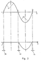
- Fig. 2 den zeitlichen Verlauf der Hübe der Pumpenteile; und
- Fig. 3 eine der Fig. 1 entsprechende Darstellung einer abgewandelten Ausführungsform.
- 1 shows a section through a metering pump.
- 2 shows the time course of the strokes of the pump parts; and
- Fig. 3 is a representation corresponding to FIG. 1 of a modified embodiment.
Die Dosierpumpe 1 weist einen Pumpenkopf 2 auf. Dieser weist eine sich in vertikaler Richtung erstreckende Pumpkammer 3 auf. An dem in vertikaler Richtung gesehen unteren Ende der Pumpkammer schließt sich ein Saugkanal 4 an, der über ein Saugventil 5 mit einer Saugleitung 6 verbunden ist. Die Saugleitung 6 führt in einen Dosiermittelbehälter 7.The metering pump 1 has a
An dem in vertikaler Richtung gesehen oberen Ende der Pumpkammer 3 mündet eine Steigleitung 8. Das in vertikaler Richtung gesehen obere Ende derselben führt über ein Druckventil 9 zu einem mit einer Dosierstelle verbindbaren Anschluß 10.At the upper end of the pump chamber 3 as seen in the vertical direction, a
In der Pumpkammer ist in der in Fig. 1 gezeigten Weise eine Dosiermembran 11 eingespannt und auf ihrer Rückseite mit einem Stößel 12 fest verbunden. Der Stößel weist einen Anschlag 13 auf. Zwischen diesem und einer festen Rahmenplatte 14 ist eine Druckfeder 15 vorgesehen, die die Membran 11 in die Saugstellung vorspannt.A
In dem mit dem Pumpenkopf 2 in der in Fig. 1 gezeigten Weise verbundenen Pumpengehäuse 17 ist eine Welle 18 gelagert, die einen Dosierexzenter 19 trägt. Das Ende 16 des Stößels liegt vorgespannt durch die Druckfeder 15 an dem Dosierexzenter 19 an.In the
Möglichst unmittelbar am oberen Ende der Steigleitung 8, also unmittelbar vor dem Druckventil 9, mündet eine Querbohrung 20. Diese führt in den Ventilraum 21 eines durch eine Membranpumpe 22 gebildeten Entlüftungsventiles. Am Ende der Querbohrung 20 ist ein Ventilsitz 23 eingearbeitet. In dem in vertikaler Richtung gesehen oberen Bereich des Ventilraumes 21 schließt ein Steigrohr 23 an, welches über ein Druckventil 24 mit einer Rücklaufleitung 25 verbunden ist. Diese führt in dem gezeigten Ausführungsbeispiel in den Dosiermittelbehälter 7 zurück.A
Die Membran ist auf ihrer dem Ventilraum abgewandten Seite mit einem Stößel 26 fest verbunden. Zwischen Rückseite der Membran und einem Wandungsteil 27 des Gehäuses ist eine Druckfeder 28 vorgesehen, die so vorgespannt ist, daß die Membran zunächst in der in Fig. 1 gezeigten Schließstellung gehalten wird.The membrane is firmly connected to a
Das der Membran abgewandte Ende des Stößels ist mit einem Joch 29 einstellbar durch eine Kontermutter 30 verbunden.The end of the plunger facing away from the membrane is adjustably connected to a
In dem Joch 29 läuft ein auf der Welle 18 sitzender zweiter Exzenter 31. Die beiden Exzenter sind in dem in Fig. 1 gezeigten Ausführungsbeispiel fest mit einem Zahnrad 32 verbunden, welches antriebsmäßig mit einem Ritzel 33 eines Antriebsmotors 34 verbunden ist.In the
Der zweite Exzenter 31 ist so ausgebildet, daß in dem gewünschten Winkelbereich der Stößel 26 so bewegt wird, daß die Membran 35 der Membranpumpe einen Saughub entgegen der Druckfeder 28 ausführt.The second eccentric 31 is designed such that the
Die beiden Exzenter 19 und 31 sind so winkelmäßig gegeneinander versetzt, daß der in Fig. 2 gezeigte Taktablauf stattfindet. Daraus ergibt sich, daß das durch die Membranpumpe 22 gebildete Ventil un einen kleinen Zeitabschnitt 36 vor dem Ausführen des Druckhubes der Dosiermembran 11 schließt. Ist der Dosierhub ausgeführt, öffnet das durch die Membranpumpe gebildete Entlüftungsventil un einen kleinen Zeitabschnitt 42 nach dem Beendigen des Dosierhubes. Während dieses Zeitabschnittes hat der Saughub 43 der Membran 11 bereits begonnen. Das Entlüftungsventil schließt durch Aufsetzen der Membran 35 in die in Fig. 1 gezeigte Stellung um einen kleinen Zeitabschnitt 44 vor dem Beenden des Saughubes. Auf diese Weise wird sichergestellt, daß beim Druckhub kein Gas in das System gelangen kann.The two
Wie aus Fig. 1 ersichtlich ist, besteht ein Abstand 37 zwischen dem Joch 29 und dem zweiten Exzenter 31. Durch diesen Abstand 37 wird die Exzenterbewegung in eine Nockenbewegung umgewandelt, wobei die Druckfeder 28 die Vorwärtsbewegung und Zuhaltekraft übernimmt. Die Druckfeder 28 kann in ihrer Zuhaltekraft so ausgelegt sein, daß sie bei einem bestimmten Druck in Pumpenkopf nachgibt, so daß das Entlüftungsventil auch noch als Überdruckventil wirkt.As can be seen from FIG. 1, there is a
Die in Fig. 3 gezeigte Ausführungsform weist zunächst alle in Fig. 1 gezeigten Merkmale auf. Zusätzlich ist zwischen der Steigleitung 8 und dem durch die Membranpumpe 22 gebildeten Entlüftungsventil ein Rückschlagventil 38 vorgesehen. Durch dieses wird das Entlüften beschleunigt.The embodiment shown in FIG. 3 initially has all the features shown in FIG. 1. In addition, between the
Ferner wird der Stößel 26 nicht von dem Motor 34 sondern von einem separat angesteuerten Hubmagneten 39 in die Saugstellung zurückgezogen. Die Erregung des Hubmagneten 39 wird über eine Steuerung 40 angesteuert. Es ist ein Sensor 45 vorgesehen, der die Drehstellung des Dosierexzenters 19 erfaßt und ein Ausgangssignal über diese Drehstellung an die Steuerung 40 liefert, um die Synchronisation des Dosierhubes der Membran 35 in der oben beschriebenen Weise mit der Membran 11 sicherzustellen.Furthermore, the
Die Steuerung 40 ist so ausgebildet, daß die Membran 35 nicht jedem Hub der Membran 11 folgt, sondern eine vorbestimmte Anzahl von Arbeitszyklen der Membran 11 in der in Figur 3 gezeigten geschlossenen Stellung verbleibt. Dadurch wird erreicht, daß die Membran 35 wesentlich weniger benutzt wird, ohne daß dadurch die Pumpleistung der Pumpe insgesamt beeinträchtigt werden würde. Die Steuerung 40 kann so eingestellt werden, daß die Zahl der ausgelassenen Hübe durch die Membran 35 in Abhängigkeit von dem zu fördernden Medium und dessen Ausgasungsneigung einstellbar ist.The
Claims (9)
Priority Applications (1)
| Application Number | Priority Date | Filing Date | Title |
|---|---|---|---|
| AT87111972T ATE50321T1 (en) | 1986-09-19 | 1987-08-18 | DOSING PUMP. |
Applications Claiming Priority (2)
| Application Number | Priority Date | Filing Date | Title |
|---|---|---|---|
| DE3631984A DE3631984C1 (en) | 1986-09-19 | 1986-09-19 | Dosing pump |
| DE3631984 | 1986-09-19 |
Publications (2)
| Publication Number | Publication Date |
|---|---|
| EP0260464A1 EP0260464A1 (en) | 1988-03-23 |
| EP0260464B1 true EP0260464B1 (en) | 1990-02-07 |
Family
ID=6309976
Family Applications (1)
| Application Number | Title | Priority Date | Filing Date |
|---|---|---|---|
| EP87111972A Expired - Lifetime EP0260464B1 (en) | 1986-09-19 | 1987-08-18 | Dosing pump |
Country Status (5)
| Country | Link |
|---|---|
| US (1) | US4865525A (en) |
| EP (1) | EP0260464B1 (en) |
| JP (1) | JPS6388283A (en) |
| AT (1) | ATE50321T1 (en) |
| DE (1) | DE3631984C1 (en) |
Families Citing this family (40)
| Publication number | Priority date | Publication date | Assignee | Title |
|---|---|---|---|---|
| DE3827489C1 (en) * | 1988-08-12 | 1989-10-12 | Gruenbeck Wasseraufbereitung Gmbh, 8884 Hoechstaedt, De | |
| GB9023552D0 (en) * | 1990-10-30 | 1990-12-12 | Domino Printing Sciences Plc | A two-stage pump for a continuous ink jet printer |
| DE9109288U1 (en) * | 1991-07-27 | 1992-09-03 | Verpaco Ag, Huenenberg, Ch | |
| DE4219663C2 (en) * | 1992-06-16 | 1996-01-18 | Prominent Dosiertechnik Gmbh | Liquid dosing pump |
| DE4241030C1 (en) * | 1992-12-05 | 1994-06-01 | Lang Apparatebau Gmbh | Dosing pump with vent valve |
| US5354183A (en) * | 1993-02-11 | 1994-10-11 | Elasis Sistema Ricerca Fiat Nel Mezzogiorno Societa Consortile Per Azioni | Pumping device with a main pumping stage and a supply pump |
| US5407424A (en) * | 1993-02-24 | 1995-04-18 | Scimed Life Systems, Inc. | Angioplasty perfusion pump |
| DE4439962A1 (en) * | 1994-11-09 | 1996-05-15 | Lang Apparatebau Gmbh | Dosing pump with venting device |
| JP3601148B2 (en) * | 1994-12-26 | 2004-12-15 | アイシン精機株式会社 | Bellows pump |
| DE19712096C1 (en) * | 1997-03-22 | 1998-04-02 | Lang Apparatebau Gmbh | Dosing pump for conveying fluids through suction valve |
| US8172546B2 (en) | 1998-11-23 | 2012-05-08 | Entegris, Inc. | System and method for correcting for pressure variations using a motor |
| US7029238B1 (en) * | 1998-11-23 | 2006-04-18 | Mykrolis Corporation | Pump controller for precision pumping apparatus |
| US6325932B1 (en) * | 1999-11-30 | 2001-12-04 | Mykrolis Corporation | Apparatus and method for pumping high viscosity fluid |
| JP3718118B2 (en) * | 2000-10-05 | 2005-11-16 | 株式会社コガネイ | Liquid ejection apparatus and liquid ejection method |
| JP3890229B2 (en) * | 2001-12-27 | 2007-03-07 | 株式会社コガネイ | Chemical liquid supply apparatus and degassing method of chemical liquid supply apparatus |
| JP3947398B2 (en) * | 2001-12-28 | 2007-07-18 | 株式会社コガネイ | Chemical solution supply apparatus and chemical solution supply method |
| JP2005076534A (en) * | 2003-08-29 | 2005-03-24 | Mitsumi Electric Co Ltd | Small pump with exhaust valve device and blood pressure meter using the same |
| US11319944B2 (en) * | 2003-10-30 | 2022-05-03 | Deka Products Limited Partnership | Disposable interconnected pump cassettes having first and second pump chambers with valved inlet and outlet connections |
| JP4851460B2 (en) * | 2004-09-20 | 2012-01-11 | メデラ ホールディング アーゲー | Method for operating a suction pump and a suction pump with an exhaust valve |
| EP1859169A2 (en) | 2004-11-23 | 2007-11-28 | Entegris, Inc. | System and method for a variable home position dispense system |
| CN101583796B (en) | 2005-11-21 | 2012-07-04 | 恩特格里公司 | Multistage pump and method for forming the same |
| US8753097B2 (en) | 2005-11-21 | 2014-06-17 | Entegris, Inc. | Method and system for high viscosity pump |
| WO2007067339A2 (en) * | 2005-12-02 | 2007-06-14 | Entegris, Inc. | Fixed volume valve system |
| WO2007067343A2 (en) * | 2005-12-02 | 2007-06-14 | Entegris, Inc. | O-ring-less low profile fittings and fitting assemblies |
| US8083498B2 (en) | 2005-12-02 | 2011-12-27 | Entegris, Inc. | System and method for position control of a mechanical piston in a pump |
| JP5253178B2 (en) | 2005-12-02 | 2013-07-31 | インテグリス・インコーポレーテッド | System and method for valve sequence of pump |
| US7940664B2 (en) * | 2005-12-02 | 2011-05-10 | Entegris, Inc. | I/O systems, methods and devices for interfacing a pump controller |
| US7850431B2 (en) | 2005-12-02 | 2010-12-14 | Entegris, Inc. | System and method for control of fluid pressure |
| US8029247B2 (en) | 2005-12-02 | 2011-10-04 | Entegris, Inc. | System and method for pressure compensation in a pump |
| US7878765B2 (en) | 2005-12-02 | 2011-02-01 | Entegris, Inc. | System and method for monitoring operation of a pump |
| WO2007067360A2 (en) * | 2005-12-05 | 2007-06-14 | Entegris, Inc. | Error volume system and method for a pump |
| TWI402423B (en) | 2006-02-28 | 2013-07-21 | Entegris Inc | System and method for operation of a pump |
| US7684446B2 (en) * | 2006-03-01 | 2010-03-23 | Entegris, Inc. | System and method for multiplexing setpoints |
| US7494265B2 (en) | 2006-03-01 | 2009-02-24 | Entegris, Inc. | System and method for controlled mixing of fluids via temperature |
| US20140056724A1 (en) * | 2012-08-27 | 2014-02-27 | Hamilton Sundstrand Corporation | Diaphragm metering pump having a degassing system |
| TR201900501T4 (en) * | 2015-06-22 | 2019-02-21 | Seko Spa | Self-venting pump provided with bleed valve and such a valve. |
| JP6177850B2 (en) * | 2015-09-17 | 2017-08-09 | 株式会社オーヤラックス | Pump device |
| JP6892982B2 (en) * | 2017-02-03 | 2021-06-23 | 応研精工株式会社 | Diaphragm pump |
| DE102018133214A1 (en) * | 2018-12-20 | 2020-06-25 | Lutz-Jesco Gmbh | Dosing pump with integrated overflow valve and valve insert for a dosing pump |
| EP4095224A1 (en) * | 2021-05-26 | 2022-11-30 | LANXESS Deutschland GmbH | Method and device for preserving beverages with pump ventilation |
Family Cites Families (9)
| Publication number | Priority date | Publication date | Assignee | Title |
|---|---|---|---|---|
| US1931691A (en) * | 1930-04-28 | 1933-10-24 | Campbell Wyant & Cannon Co | Fuel pump for oil engines |
| US2308974A (en) * | 1939-11-01 | 1943-01-19 | Lyndus E Harper | Positive displacement pump |
| CH457146A (en) * | 1967-11-20 | 1968-05-31 | Glutz Blotzheim Nachfolger Ag | Electromagnetic oscillating armature pump |
| US3680985A (en) * | 1970-12-28 | 1972-08-01 | Mec O Matic The | Pump |
| DE2651614C2 (en) * | 1976-11-12 | 1984-10-04 | Lang Apparatebau GmbH, 8227 Siegsdorf | Dosing pump |
| DE2803470B2 (en) * | 1978-01-27 | 1980-06-04 | Dulger, Viktor, 6900 Heidelberg | Ventilation device for a liquid piston pump, in particular a metering pump |
| US4236881A (en) * | 1978-05-03 | 1980-12-02 | Ecodyne Corporation | Liquid metering pump |
| US4278406A (en) * | 1979-11-07 | 1981-07-14 | R. W. Beckett Corporation | Electromagnetic pump |
| JPS6128073U (en) * | 1984-07-25 | 1986-02-19 | 昭和電線電纜株式会社 | test equipment |
-
1986
- 1986-09-19 DE DE3631984A patent/DE3631984C1/en not_active Expired
-
1987
- 1987-08-18 EP EP87111972A patent/EP0260464B1/en not_active Expired - Lifetime
- 1987-08-18 AT AT87111972T patent/ATE50321T1/en not_active IP Right Cessation
- 1987-08-25 US US07/089,226 patent/US4865525A/en not_active Expired - Fee Related
- 1987-09-19 JP JP62233759A patent/JPS6388283A/en active Pending
Also Published As
| Publication number | Publication date |
|---|---|
| DE3631984C1 (en) | 1987-12-17 |
| US4865525A (en) | 1989-09-12 |
| EP0260464A1 (en) | 1988-03-23 |
| ATE50321T1 (en) | 1990-02-15 |
| JPS6388283A (en) | 1988-04-19 |
Similar Documents
| Publication | Publication Date | Title |
|---|---|---|
| EP0260464B1 (en) | Dosing pump | |
| EP0354484B1 (en) | Dosing pump | |
| EP0791138B1 (en) | Metering pump with an air-purge device | |
| DE3900327A1 (en) | DEVICE FOR AN ANTI-BLOCKING SYSTEM | |
| EP2609332A1 (en) | Membrane pump having an inertially controlled leak extension valve | |
| EP0688954A1 (en) | Controlled replenishment device for high pressure membrane pumps | |
| DE2651614C2 (en) | Dosing pump | |
| DE2807514C3 (en) | Diaphragm pump | |
| EP0007109A1 (en) | Apparatus for metering a solution of chemicals to a stream of liquid | |
| DE2837208A1 (en) | FUEL PROCESSING DEVICE | |
| DE4130729A1 (en) | BRAKE PRESSURE CONTROL DEVICE FOR A HYDRAULIC MOTOR VEHICLE BRAKE SYSTEM | |
| CH181340A (en) | Device for the mechanical injection of fuel in internal combustion engines. | |
| DE3928411C2 (en) | ||
| EP0316537B1 (en) | Dosing pump | |
| DE2319249C3 (en) | Pump for conveying grease in lubrication systems | |
| DE3508170A1 (en) | HYDRAULIC DEVICE | |
| DE10035537A1 (en) | Cam driven piston pump has a retainer to hold the inlet valve open until the start of the compression stroke | |
| DE2600572A1 (en) | DEVICE FOR DOSING CHEMICAL SOLUTIONS | |
| DE729083C (en) | Hydraulically operated fuel injector for internal combustion engines | |
| EP1658438A1 (en) | Liquid pump | |
| DE155340C (en) | ||
| DE4417213A1 (en) | System for feeding fluid medium from tank | |
| DE3003832C2 (en) | Pump, especially diaphragm pump | |
| AT363782B (en) | DEVICE FOR DOSING A CHEMICAL SOLUTION IN FLOWING FRESH LIQUID | |
| EP1146224A1 (en) | Fuel-supply device for an internal combustion engine |
Legal Events
| Date | Code | Title | Description |
|---|---|---|---|
| PUAI | Public reference made under article 153(3) epc to a published international application that has entered the european phase |
Free format text: ORIGINAL CODE: 0009012 |
|
| AK | Designated contracting states |
Kind code of ref document: A1 Designated state(s): AT BE CH FR GB IT LI NL |
|
| 17P | Request for examination filed |
Effective date: 19880511 |
|
| 17Q | First examination report despatched |
Effective date: 19880912 |
|
| GRAA | (expected) grant |
Free format text: ORIGINAL CODE: 0009210 |
|
| AK | Designated contracting states |
Kind code of ref document: B1 Designated state(s): AT BE CH FR GB IT LI NL |
|
| REF | Corresponds to: |
Ref document number: 50321 Country of ref document: AT Date of ref document: 19900215 Kind code of ref document: T |
|
| ET | Fr: translation filed | ||
| GBT | Gb: translation of ep patent filed (gb section 77(6)(a)/1977) | ||
| ITF | It: translation for a ep patent filed |
Owner name: SAIC BREVETTI S.R.L. |
|
| PLBE | No opposition filed within time limit |
Free format text: ORIGINAL CODE: 0009261 |
|
| STAA | Information on the status of an ep patent application or granted ep patent |
Free format text: STATUS: NO OPPOSITION FILED WITHIN TIME LIMIT |
|
| 26N | No opposition filed | ||
| ITTA | It: last paid annual fee | ||
| PGFP | Annual fee paid to national office [announced via postgrant information from national office to epo] |
Ref country code: GB Payment date: 19960802 Year of fee payment: 10 |
|
| PGFP | Annual fee paid to national office [announced via postgrant information from national office to epo] |
Ref country code: FR Payment date: 19960810 Year of fee payment: 10 |
|
| PGFP | Annual fee paid to national office [announced via postgrant information from national office to epo] |
Ref country code: BE Payment date: 19960822 Year of fee payment: 10 Ref country code: AT Payment date: 19960822 Year of fee payment: 10 |
|
| PGFP | Annual fee paid to national office [announced via postgrant information from national office to epo] |
Ref country code: CH Payment date: 19960823 Year of fee payment: 10 |
|
| PGFP | Annual fee paid to national office [announced via postgrant information from national office to epo] |
Ref country code: NL Payment date: 19960828 Year of fee payment: 10 |
|
| PG25 | Lapsed in a contracting state [announced via postgrant information from national office to epo] |
Ref country code: GB Free format text: LAPSE BECAUSE OF NON-PAYMENT OF DUE FEES Effective date: 19970818 Ref country code: AT Free format text: LAPSE BECAUSE OF NON-PAYMENT OF DUE FEES Effective date: 19970818 |
|
| PG25 | Lapsed in a contracting state [announced via postgrant information from national office to epo] |
Ref country code: LI Free format text: LAPSE BECAUSE OF NON-PAYMENT OF DUE FEES Effective date: 19970831 Ref country code: CH Free format text: LAPSE BECAUSE OF NON-PAYMENT OF DUE FEES Effective date: 19970831 Ref country code: BE Free format text: LAPSE BECAUSE OF NON-PAYMENT OF DUE FEES Effective date: 19970831 |
|
| BERE | Be: lapsed |
Owner name: GRUNBECK WASSERAUFBEREITUNG G.M.B.H. Effective date: 19970831 |
|
| PG25 | Lapsed in a contracting state [announced via postgrant information from national office to epo] |
Ref country code: NL Free format text: LAPSE BECAUSE OF NON-PAYMENT OF DUE FEES Effective date: 19980301 |
|
| GBPC | Gb: european patent ceased through non-payment of renewal fee |
Effective date: 19970818 |
|
| REG | Reference to a national code |
Ref country code: CH Ref legal event code: PL |
|
| PG25 | Lapsed in a contracting state [announced via postgrant information from national office to epo] |
Ref country code: FR Free format text: LAPSE BECAUSE OF NON-PAYMENT OF DUE FEES Effective date: 19980430 |
|
| NLV4 | Nl: lapsed or anulled due to non-payment of the annual fee |
Effective date: 19980301 |
|
| REG | Reference to a national code |
Ref country code: FR Ref legal event code: ST |
|
| PG25 | Lapsed in a contracting state [announced via postgrant information from national office to epo] |
Ref country code: IT Free format text: LAPSE BECAUSE OF NON-PAYMENT OF DUE FEES;WARNING: LAPSES OF ITALIAN PATENTS WITH EFFECTIVE DATE BEFORE 2007 MAY HAVE OCCURRED AT ANY TIME BEFORE 2007. THE CORRECT EFFECTIVE DATE MAY BE DIFFERENT FROM THE ONE RECORDED. Effective date: 20050818 |