EP0260036A2 - Cyrostat assembly - Google Patents
Cyrostat assembly Download PDFInfo
- Publication number
- EP0260036A2 EP0260036A2 EP87307603A EP87307603A EP0260036A2 EP 0260036 A2 EP0260036 A2 EP 0260036A2 EP 87307603 A EP87307603 A EP 87307603A EP 87307603 A EP87307603 A EP 87307603A EP 0260036 A2 EP0260036 A2 EP 0260036A2
- Authority
- EP
- European Patent Office
- Prior art keywords
- heat
- assembly according
- wall
- refrigeration system
- coupling means
- Prior art date
- Legal status (The legal status is an assumption and is not a legal conclusion. Google has not performed a legal analysis and makes no representation as to the accuracy of the status listed.)
- Granted
Links
- 238000005057 refrigeration Methods 0.000 claims abstract description 35
- 238000010168 coupling process Methods 0.000 claims description 19
- RYGMFSIKBFXOCR-UHFFFAOYSA-N Copper Chemical compound [Cu] RYGMFSIKBFXOCR-UHFFFAOYSA-N 0.000 claims description 18
- 229910052802 copper Inorganic materials 0.000 claims description 18
- 239000010949 copper Substances 0.000 claims description 18
- 230000008878 coupling Effects 0.000 claims description 18
- 238000005859 coupling reaction Methods 0.000 claims description 18
- 230000005855 radiation Effects 0.000 claims description 18
- 239000002826 coolant Substances 0.000 claims description 14
- IJGRMHOSHXDMSA-UHFFFAOYSA-N Atomic nitrogen Chemical compound N#N IJGRMHOSHXDMSA-UHFFFAOYSA-N 0.000 description 32
- 239000007788 liquid Substances 0.000 description 18
- 229910052757 nitrogen Inorganic materials 0.000 description 16
- 239000001307 helium Substances 0.000 description 13
- 229910052734 helium Inorganic materials 0.000 description 13
- SWQJXJOGLNCZEY-UHFFFAOYSA-N helium atom Chemical compound [He] SWQJXJOGLNCZEY-UHFFFAOYSA-N 0.000 description 13
- 238000005481 NMR spectroscopy Methods 0.000 description 5
- 230000000712 assembly Effects 0.000 description 5
- 238000000429 assembly Methods 0.000 description 5
- 239000007789 gas Substances 0.000 description 2
- 229910000838 Al alloy Inorganic materials 0.000 description 1
- 229910001369 Brass Inorganic materials 0.000 description 1
- 239000010951 brass Substances 0.000 description 1
- 238000003384 imaging method Methods 0.000 description 1
- 229910052738 indium Inorganic materials 0.000 description 1
- APFVFJFRJDLVQX-UHFFFAOYSA-N indium atom Chemical compound [In] APFVFJFRJDLVQX-UHFFFAOYSA-N 0.000 description 1
- 238000003780 insertion Methods 0.000 description 1
- 230000037431 insertion Effects 0.000 description 1
- 239000000463 material Substances 0.000 description 1
- 229910052751 metal Inorganic materials 0.000 description 1
- 239000002184 metal Substances 0.000 description 1
- 239000010935 stainless steel Substances 0.000 description 1
- 229910001220 stainless steel Inorganic materials 0.000 description 1
Images


Classifications
-
- G—PHYSICS
- G01—MEASURING; TESTING
- G01R—MEASURING ELECTRIC VARIABLES; MEASURING MAGNETIC VARIABLES
- G01R33/00—Arrangements or instruments for measuring magnetic variables
- G01R33/20—Arrangements or instruments for measuring magnetic variables involving magnetic resonance
- G01R33/28—Details of apparatus provided for in groups G01R33/44 - G01R33/64
- G01R33/38—Systems for generation, homogenisation or stabilisation of the main or gradient magnetic field
- G01R33/381—Systems for generation, homogenisation or stabilisation of the main or gradient magnetic field using electromagnets
- G01R33/3815—Systems for generation, homogenisation or stabilisation of the main or gradient magnetic field using electromagnets with superconducting coils, e.g. power supply therefor
-
- F—MECHANICAL ENGINEERING; LIGHTING; HEATING; WEAPONS; BLASTING
- F17—STORING OR DISTRIBUTING GASES OR LIQUIDS
- F17C—VESSELS FOR CONTAINING OR STORING COMPRESSED, LIQUEFIED OR SOLIDIFIED GASES; FIXED-CAPACITY GAS-HOLDERS; FILLING VESSELS WITH, OR DISCHARGING FROM VESSELS, COMPRESSED, LIQUEFIED, OR SOLIDIFIED GASES
- F17C3/00—Vessels not under pressure
- F17C3/02—Vessels not under pressure with provision for thermal insulation
- F17C3/08—Vessels not under pressure with provision for thermal insulation by vacuum spaces, e.g. Dewar flask
- F17C3/085—Cryostats
-
- F—MECHANICAL ENGINEERING; LIGHTING; HEATING; WEAPONS; BLASTING
- F25—REFRIGERATION OR COOLING; COMBINED HEATING AND REFRIGERATION SYSTEMS; HEAT PUMP SYSTEMS; MANUFACTURE OR STORAGE OF ICE; LIQUEFACTION SOLIDIFICATION OF GASES
- F25D—REFRIGERATORS; COLD ROOMS; ICE-BOXES; COOLING OR FREEZING APPARATUS NOT OTHERWISE PROVIDED FOR
- F25D19/00—Arrangement or mounting of refrigeration units with respect to devices or objects to be refrigerated, e.g. infrared detectors
- F25D19/006—Thermal coupling structure or interface
Definitions
- the invention relates to cryostat assemblies comprising at least one substantially heat insulating wall surrounding a cooled region for restricting heat flow into the region.
- cryostat assemblies comprising at least one substantially heat insulating wall surrounding a cooled region for restricting heat flow into the region.
- Cryostat assemblies of the kind described are used in a variety of fields one of which is the field of nuclear magnetic resonance (NMR) imaging wherein superconducting coils of an electromagnet are sitatuated within the cryostat.
- NMR nuclear magnetic resonance
- the coils of the magnet take up a superconducting state it is necessary to cool them to very low temperatures in the order of 4K and conventionally this is achieved by making use of a liquid helium vessel within which the coils are mounted, the helium vessel being sandwiched within a radiation shield, the radiation shield being sandwiched within a liquid nitrogen vessel, and the liquid nitrogen vessel being sandwiched within an evacuated vessel.
- This series of insulating jackets enables the coils to be maintained at the required low temperature.
- cryostat assemblies there is a continuous vapourising of the liquid helium and liquid nitrogen which is boiled off and fresh helium and nitrogen has to be supplied to the respective vessels. This degree of boil off is expensive and generally undesirable.
- a cryostat assembly comprises at least one substantially heat insulating wall surrounding a cooled region for restricting heat flow into the cooled region; and a refrigeration system having a heat absorbing portion coupled by coupling means with the wall to enable heat to transfer to the heat absorbing portion via the coupling means, and a heat evacuating portion to enable absorbed heat to be evacuated from the cryostat assembly.
- a refrigeration system is added to assist in removing heat from the or each wall to which it is coupled. It has been found that this considerably reduces the liquid coolant consumption where the system includes a coolant vessel. For example, in one system it has been found that liquid nitrogen consumption has been reduced by about 1 litre per hour while liquid helium consumption is reduced by about 200 cc per hour. In some cases, the refrigeration system can reduce liquid nitrogen consumption to substantially zero.
- substantially heat insulating wall could comprise part of a wall of a coolant vessel or a heat radiation shield.
- the refrigeration system may be of any suitable conventional type such as of the Gifford McMahon type using a closed helium gas cycle.
- the refrigeration system is a two-stage system, each stage being connected with a different part of the remainder of the assembly.
- a first (higher temperature) stage of the system may be coupled for heat transfer with an outer radiation shield or coolant vessel and a second (lower temperature) stage may be coupled for heat transfer with an inner radiation shield.
- a single stage refrigeration system could be used which would typically be coupled for heat transfer with a wall defined by at least part of a coolant vessel.
- the elements of the assembly are supported by a plurality of support rods. These provide an undesirable source of heat supply to the vessel or shield to which they are connected and are conventionally made of low heat conductivity material. However, some heat conduction does take place and it is particularly convenient if the refrigeration system is coupled for heat transfer with at least one of the support rods. This coupling may be direct in the sense that the coupling means extends between the support and the refrigeration system, but would typically be indirect. Thus, at least one of the support rods is coupled with another wall or vessel which itself is coupled with the refrigeration system whereby a heat flow path exists from the rod via the wall or vessel to the refrigeration system.
- the or each coupling means comprises a flexible, highly heat conductive linkage. Flexibility is desirable to cope with relative movement between the refrigeration system and the element to which it is connected and high heat conductivity is required for rapid dissipation of heat.
- the coupling means comprises copper braid.
- the precise dimensions of the braid depends on the powers available at the refrigeration system and on the other properties of the cryostat assembly.
- the refrigeration system comprises a support housing, and a refrigeration unit removably mounted in the support housing, heat conducting contacts being provided on the unit and in the support housing connected with the coupling means whereby when the unit is fully mounted in the support housing the contacts engage one another to provide a heat path between the unit and the coupling means through the support housing, the support housing being adapted to restrict heat flow from outside the cryostat assembly to the coupling means.
- This arrangement enables the refrigeration unit to be removed and inserted either for replacement or for repair without having to dissassemble the remainder of the cryostat and in particular without having to empty the coolant vessel or vessels.
- FIG. 1 illustrates the general form of a cryostat assembly which comprises a number of cylindrical, aluminium alloy, or stainless steel walls which are connected to define liquid coolant vessels and radiation shields as will be explained.
- a central wall 1 defines with another, coaxial wall 1 ⁇ and end walls 1 ⁇ a liquid helium vessel 2.
- the vessel 2 on one side is surrounded by a cylindrical wall 3 defining an inner radiation shield and by another radiation shield 3 ⁇ on its other side connected with end walls 3 ⁇ .
- a liquid nitrogen vessel defined by two pairs of cylindrical walls 4,5 and its extension 4 ⁇ connected to end wall extension 4 ⁇ sandwiches the radiation shields.
- An outer vacuum jacket 6 surrounds the liquid nitrogen vessel and extension.
- a cylindrical bore 60 is defined by the innermost cylindrical wall defining part of the wall of the inner vacuum jacket.
- coils of a main superconducting magnet 61 are situated within the helium vessel 2 which constitutes a cooled region.
- a turret 62 is positioned on top of the cryostat assembly through which a helium boil-off port 63 and one or more nitrogen boil-off ports 64 extend.
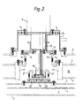
- FIG 2 illustrates part of the cryostat assembly shown in Figure 1 and in particular the section indicated at A in Figure 1.
- the refrigeration elements shown in Figure 2 have been omitted.
- a turret 7 having a vacuum jacket is bolted to the wall of the jacket 6.
- a two stage refrigerator unit 8 of the Gifford McMahon type (such as manufactured by Leybold Heraeus) is bolted to the turret 7 via flanges 9, 10 and a seal 11.
- the first (higher temperature) stage of the refrigerator 12 is bolted to a higher conductivity copper flange 13 which in turn is bolted to an annular, auxiliary flange 14 to which one end of a number of flexible, high conductivity copper braid links 15 are soft soldered.
- each link 15 is soft soldered to an annular, high conductivity copper flange 16 bolted to an annular end wall 17 of the liquid nitrogen vessel 18.
- the second (lower temperature) stage 19 of the refrigerator 8 is bonded to a high conductivity copper flange 20 to which a number of further high conductivity copper braid links 21 are soft soldered.
- the other end of the links 21 are soft soldered to a copper flange 22 bolted via an intermediate copper flange 23 to the inner shield 3.
- the arrangement shown in Figure 2 enables the refrigeration power to be transferred from the first stage 12 to the liquid nitrogen vessel 18 via the flanges 13, 14 (which may be segmented) and the links 15 and to the inner shield 3 via the flanges 20, 22, 23 and the links 21.
- the links 15, 21 are of sufficient length, cross-sectional area, and number to provide for movement between the refrigerator and the parts to which it is connected and to adequately transfer the refrigerator power to the nitrogen vessel and shield.
- the precise dimensions of the braids depends on the powers available at each stage of the refrigerator used and on the cryostat system.
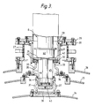
- FIG 3 shows an arrangement in which removal and replacement of the refrigeration unit 8 can be achieved very simply without coolant removal.
- FIG 3 illustrates only a part of another cryostat assembly including three concentric walls 24, 25, 26.
- the wall 24 defines the outer cylinder of the inner radiation shield and is surrounded by the wall 25 which constitutes the outer cylinder of the outer radiation shield. In this case there is no nitrogen vessel.
- the shield 25 is surrounded by an outer vacuum jacket 26.
- An anti-vibration mounting is provided part of which is shown at 27.
- the refrigeration unit 8 is mounted to the remainder of the cryostat assembly by insertion into a support housing 28.
- the support housing 28 has an outer flange 29 bolted to a turret flange 30.
- Flange 30 is supported from the lower bolted flange by a set of springs which are adjusted by means of screws and the intermediate flange so that the flange 30 is resiliently supported against the force of air pressure.
- the resiliency of this support considerably reduces the vibration from the refrigerator being transmitted to the outer vacuum wall 26, whence it would be re-radiated into the environment.
- a radially inner portion of the housing 28 is defined by a triple wall 31 comprising three concentric cylinders terminating in an inner flange 32 of highly conductive copper.
- the triple wall 31 is to increase the heat path length between room temperature and the outer shield 26.
- the flange 32 may be equated with the flange 13 in Figure 2 and links 33 of highly conductive copper braid are soft soldered between the flange 32 and another copper flange 34 coupled with the radiation shield 25.
- the housing 28 has a further inner, cylindrical wall part 35 sealed to a radially inner surface of the flange 32 and supporting at its lower end a copper nose 36 sealed to its outer surface. Copper braid links 37 are soft soldered between the nose 36 and a copper plate 38 coupled with the wall 24.
- the refrigeration unit 8 is mounted within the support housing 28 so that a copper flange 39 connected to the first stage 40 of the unit 8 is pressed against an indium metal pressure contact 42 to enable the first stage 40 to be coupled for heat transfer with the links 33.
- the second stage 43 of the refrigerator unit includes a copper cylinder 44 which forms a close fit within the nose 36. Contact between the cylinder 44 and the nose 36 is achieved by filling a cavity 45 within the housing 28 with helium gas at about 1 atmosphere (although much lower pressures are feasible).
- FIG. 4 illustrates a coolant vessel 46 (such as a helium vessel) supported by a rod 47 extending between the vessel 46 and an outer vessel 48 (such as a nitrogen vessel) through an aperture 49 in an inner radiation shield 50.
- the vessel 48 is supported by a tension rod 51 to an outer vacuum jacket 52. Since there may be some heat conduction along the rod 47 or 51, it is advantagous to couple the support rods with one of the walls of the cryostat to which the refrigeration unit 8 is coupled.
- a suitable connection may be achieved between the support rod 47 and the inner shield 3 which, as seen in Figure 2, is coupled to the second stage of the refrigerator unit 8.
- Coupling between the rod 47 and the shield 3 is achieved by connecting a flexible copper braid link 53 bolted to the inner shield 3 and whipped to the support rod by a brass wire. Other coupling methods are also possible.
Landscapes
- Physics & Mathematics (AREA)
- Engineering & Computer Science (AREA)
- Thermal Sciences (AREA)
- Mechanical Engineering (AREA)
- General Engineering & Computer Science (AREA)
- Electromagnetism (AREA)
- Condensed Matter Physics & Semiconductors (AREA)
- General Physics & Mathematics (AREA)
- Chemical & Material Sciences (AREA)
- Combustion & Propulsion (AREA)
- Containers, Films, And Cooling For Superconductive Devices (AREA)
Abstract
Description
- The invention relates to cryostat assemblies comprising at least one substantially heat insulating wall surrounding a cooled region for restricting heat flow into the region. Such assemblies are hereinafter referred to as of the kind described.
- Cryostat assemblies of the kind described are used in a variety of fields one of which is the field of nuclear magnetic resonance (NMR) imaging wherein superconducting coils of an electromagnet are sitatuated within the cryostat. In order that the coils of the magnet take up a superconducting state it is necessary to cool them to very low temperatures in the order of 4K and conventionally this is achieved by making use of a liquid helium vessel within which the coils are mounted, the helium vessel being sandwiched within a radiation shield, the radiation shield being sandwiched within a liquid nitrogen vessel, and the liquid nitrogen vessel being sandwiched within an evacuated vessel. This series of insulating jackets enables the coils to be maintained at the required low temperature.
- One of the problems with these cryostat assemblies is that there is a continuous vapourising of the liquid helium and liquid nitrogen which is boiled off and fresh helium and nitrogen has to be supplied to the respective vessels. This degree of boil off is expensive and generally undesirable.
- In accordance with the present invention, a cryostat assembly comprises at least one substantially heat insulating wall surrounding a cooled region for restricting heat flow into the cooled region; and a refrigeration system having a heat absorbing portion coupled by coupling means with the wall to enable heat to transfer to the heat absorbing portion via the coupling means, and a heat evacuating portion to enable absorbed heat to be evacuated from the cryostat assembly.
- With this cryostat assembly, a refrigeration system is added to assist in removing heat from the or each wall to which it is coupled. It has been found that this considerably reduces the liquid coolant consumption where the system includes a coolant vessel. For example, in one system it has been found that liquid nitrogen consumption has been reduced by about 1 litre per hour while liquid helium consumption is reduced by about 200 cc per hour. In some cases, the refrigeration system can reduce liquid nitrogen consumption to substantially zero.
- It will be appreciated that the substantially heat insulating wall could comprise part of a wall of a coolant vessel or a heat radiation shield.
- The refrigeration system may be of any suitable conventional type such as of the Gifford McMahon type using a closed helium gas cycle. Conveniently, the refrigeration system is a two-stage system, each stage being connected with a different part of the remainder of the assembly. For example, a first (higher temperature) stage of the system may be coupled for heat transfer with an outer radiation shield or coolant vessel and a second (lower temperature) stage may be coupled for heat transfer with an inner radiation shield.
- In other examples, a single stage refrigeration system could be used which would typically be coupled for heat transfer with a wall defined by at least part of a coolant vessel.
- In many conventional cryostat assemblies, the elements of the assembly are supported by a plurality of support rods. These provide an undesirable source of heat supply to the vessel or shield to which they are connected and are conventionally made of low heat conductivity material. However, some heat conduction does take place and it is particularly convenient if the refrigeration system is coupled for heat transfer with at least one of the support rods. This coupling may be direct in the sense that the coupling means extends between the support and the refrigeration system, but would typically be indirect. Thus, at least one of the support rods is coupled with another wall or vessel which itself is coupled with the refrigeration system whereby a heat flow path exists from the rod via the wall or vessel to the refrigeration system.
- Preferably, the or each coupling means comprises a flexible, highly heat conductive linkage. Flexibility is desirable to cope with relative movement between the refrigeration system and the element to which it is connected and high heat conductivity is required for rapid dissipation of heat.
- Conveniently, the coupling means comprises copper braid. The precise dimensions of the braid depends on the powers available at the refrigeration system and on the other properties of the cryostat assembly.
- In some cases, it is desirable to be able to replace the refrigeration system with an alternative system or to remove the system for repair. In general, this would require considerable dissassembly of the cryostat, including for example removing coolant.
- Preferably, therefore, the refrigeration system comprises a support housing, and a refrigeration unit removably mounted in the support housing, heat conducting contacts being provided on the unit and in the support housing connected with the coupling means whereby when the unit is fully mounted in the support housing the contacts engage one another to provide a heat path between the unit and the coupling means through the support housing, the support housing being adapted to restrict heat flow from outside the cryostat assembly to the coupling means.
- This arrangement enables the refrigeration unit to be removed and inserted either for replacement or for repair without having to dissassemble the remainder of the cryostat and in particular without having to empty the coolant vessel or vessels.
- It is particularly convenient if the walls of the support housing are insulated against heat flow.
- Some examples of cryostats in accordance with the present invention will now be described with reference to the accompanying drawings, in which:-
- Figure 1 is a partly cut away side elevation of a cryostat with the refrigeration system omitted;
- Figure 2 is a partial cross-section through a first example of a cryostat assembly according to the invention for use in nuclear magnetic resonance apparatus;
- Figure 3 is a view similar to Figure 2 but of a second example;
- Figure 4 is a partial perspective view from one end with some parts removed of a cryostat assembly illustrating support rods; and,
- Figure 5 illstrates the coupling of a support rod within an inner radiation shield.
- Figure 1 illustrates the general form of a cryostat assembly which comprises a number of cylindrical, aluminium alloy, or stainless steel walls which are connected to define liquid coolant vessels and radiation shields as will be explained. A
central wall 1 defines with another, coaxial wall 1ʹ and end walls 1ʺ aliquid helium vessel 2. Thevessel 2 on one side is surrounded by acylindrical wall 3 defining an inner radiation shield and by another radiation shield 3ʹ on its other side connected with end walls 3ʺ. A liquid nitrogen vessel defined by two pairs ofcylindrical walls outer vacuum jacket 6 surrounds the liquid nitrogen vessel and extension. Acylindrical bore 60 is defined by the innermost cylindrical wall defining part of the wall of the inner vacuum jacket. In addition, in nuclear magnetic resonance apparatus, coils of a mainsuperconducting magnet 61 are situated within thehelium vessel 2 which constitutes a cooled region. - A
turret 62 is positioned on top of the cryostat assembly through which a helium boil-offport 63 and one or more nitrogen boil-offports 64 extend. - Figure 2 illustrates part of the cryostat assembly shown in Figure 1 and in particular the section indicated at A in Figure 1. In Figure 1 the refrigeration elements shown in Figure 2 have been omitted.
- A
turret 7 having a vacuum jacket is bolted to the wall of thejacket 6. A two stage refrigerator unit 8 of the Gifford McMahon type (such as manufactured by Leybold Heraeus) is bolted to theturret 7 viaflanges 9, 10 and aseal 11. The first (higher temperature) stage of therefrigerator 12 is bolted to a higherconductivity copper flange 13 which in turn is bolted to an annular,auxiliary flange 14 to which one end of a number of flexible, high conductivitycopper braid links 15 are soft soldered. - The other end of each
link 15 is soft soldered to an annular, highconductivity copper flange 16 bolted to anannular end wall 17 of theliquid nitrogen vessel 18. - The second (lower temperature)
stage 19 of the refrigerator 8 is bonded to a highconductivity copper flange 20 to which a number of further high conductivitycopper braid links 21 are soft soldered. The other end of thelinks 21 are soft soldered to acopper flange 22 bolted via anintermediate copper flange 23 to theinner shield 3. - The arrangement shown in Figure 2 enables the refrigeration power to be transferred from the
first stage 12 to theliquid nitrogen vessel 18 via theflanges 13, 14 (which may be segmented) and thelinks 15 and to theinner shield 3 via theflanges links 21. - The
links - It has been found that the system shown in Figure 2, when used in NMR apparatus, enables a reduction in liquid nitrogen consumption of about 1 litre per hour, compared with the unrefrigerated system, and a reduction in liqiud helium consumption of about 200 cc per hour.
- It will be seen from Figure 2 that if it is desired to remove the refrigeration unit 8 for the purposes of repair or replacement, it is necessary to destroy the vacuum within the vacuum jacket and this requires the preliminary removal of all liquid helium and liquid nitrogen coolant. Figure 3 shows an arrangement in which removal and replacement of the refrigeration unit 8 can be achieved very simply without coolant removal.
- Figure 3 illustrates only a part of another cryostat assembly including three
concentric walls wall 24 defines the outer cylinder of the inner radiation shield and is surrounded by thewall 25 which constitutes the outer cylinder of the outer radiation shield. In this case there is no nitrogen vessel. Theshield 25 is surrounded by anouter vacuum jacket 26. An anti-vibration mounting is provided part of which is shown at 27. In this example, the refrigeration unit 8 is mounted to the remainder of the cryostat assembly by insertion into asupport housing 28. Thesupport housing 28 has an outer flange 29 bolted to a turret flange 30. Flange 30 is supported from the lower bolted flange by a set of springs which are adjusted by means of screws and the intermediate flange so that the flange 30 is resiliently supported against the force of air pressure. The resiliency of this support considerably reduces the vibration from the refrigerator being transmitted to theouter vacuum wall 26, whence it would be re-radiated into the environment. A radially inner portion of thehousing 28 is defined by atriple wall 31 comprising three concentric cylinders terminating in an inner flange 32 of highly conductive copper. Thetriple wall 31 is to increase the heat path length between room temperature and theouter shield 26. The flange 32 may be equated with theflange 13 in Figure 2 and links 33 of highly conductive copper braid are soft soldered between the flange 32 and anothercopper flange 34 coupled with theradiation shield 25. Thehousing 28 has a further inner, cylindrical wall part 35 sealed to a radially inner surface of the flange 32 and supporting at its lower end a copper nose 36 sealed to its outer surface. Copper braid links 37 are soft soldered between the nose 36 and acopper plate 38 coupled with thewall 24. - The refrigeration unit 8 is mounted within the
support housing 28 so that acopper flange 39 connected to thefirst stage 40 of the unit 8 is pressed against an indiummetal pressure contact 42 to enable thefirst stage 40 to be coupled for heat transfer with the links 33. - The
second stage 43 of the refrigerator unit includes a copper cylinder 44 which forms a close fit within the nose 36. Contact between the cylinder 44 and the nose 36 is achieved by filling acavity 45 within thehousing 28 with helium gas at about 1 atmosphere (although much lower pressures are feasible). - If it is desired to remove or replace the refrigeration unit 8, this is simply unbolted at its outer end and slid out of the
support housing 28. This removal does not open any access to the jackets of the cryostat and so any vacuum within those jackets is not destroyed. - In a typical cryostat assembly, the various vessels and shields are supported by means of elongate tension rods as partly shown in Figure 4. Figure 4 illustrates a coolant vessel 46 (such as a helium vessel) supported by a
rod 47 extending between thevessel 46 and an outer vessel 48 (such as a nitrogen vessel) through anaperture 49 in aninner radiation shield 50. In a similar way thevessel 48 is supported by atension rod 51 to an outer vacuum jacket 52. Since there may be some heat conduction along therod support rod 47 and theinner shield 3 which, as seen in Figure 2, is coupled to the second stage of the refrigerator unit 8. Coupling between therod 47 and theshield 3 is achieved by connecting a flexiblecopper braid link 53 bolted to theinner shield 3 and whipped to the support rod by a brass wire. Other coupling methods are also possible.
Claims (11)
Applications Claiming Priority (2)
| Application Number | Priority Date | Filing Date | Title |
|---|---|---|---|
| JP1986139251U JPH0629635Y2 (en) | 1986-09-09 | 1986-09-09 | Cryostat |
| JP139251/86U | 1986-09-09 |
Publications (3)
| Publication Number | Publication Date |
|---|---|
| EP0260036A2 true EP0260036A2 (en) | 1988-03-16 |
| EP0260036A3 EP0260036A3 (en) | 1988-08-17 |
| EP0260036B1 EP0260036B1 (en) | 1991-03-20 |
Family
ID=15240958
Family Applications (1)
| Application Number | Title | Priority Date | Filing Date |
|---|---|---|---|
| EP87307603A Expired EP0260036B1 (en) | 1986-09-09 | 1987-08-27 | Cyrostat assembly |
Country Status (4)
| Country | Link |
|---|---|
| US (2) | US4777807A (en) |
| EP (1) | EP0260036B1 (en) |
| JP (1) | JPH0629635Y2 (en) |
| DE (1) | DE3768742D1 (en) |
Cited By (18)
| Publication number | Priority date | Publication date | Assignee | Title |
|---|---|---|---|---|
| EP0284874A1 (en) * | 1987-04-02 | 1988-10-05 | General Electric Company | Thermal interface for interconnecting a cryocooler and a magnetic resonance imaging cryostat |
| EP0350265A2 (en) * | 1988-07-05 | 1990-01-10 | General Electric Company | Heat conductive, electrically insulative joint |
| EP0350266A2 (en) * | 1988-07-05 | 1990-01-10 | General Electric Company | Coupling a cryogenic cooler to a body to be cooled |
| EP0359262A2 (en) * | 1988-09-16 | 1990-03-21 | Hitachi, Ltd. | Cryostat with refrigerator containing superconductive magnet |
| EP0366818A1 (en) * | 1988-11-02 | 1990-05-09 | Leybold Aktiengesellschaft | Cryostatic temperature regulator with a liquid nitrogen bath |
| EP0414443A1 (en) * | 1989-08-17 | 1991-02-27 | General Electric Company | Refrigerated MR magnet support system |
| DE4129547A1 (en) * | 1990-09-05 | 1992-03-12 | Mitsubishi Electric Corp | COLD CONTROL |
| US5235818A (en) * | 1990-09-05 | 1993-08-17 | Mitsubishi Denki Kabushiki Kaisha | Cryostat |
| DE4143392C2 (en) * | 1990-09-05 | 1996-03-07 | Mitsubishi Electric Corp | Cooling controller for superconducting magnet indicating NMR |
| DE19533555A1 (en) * | 1995-09-11 | 1997-03-13 | Siemens Ag | Device for indirect cooling of an electrical device |
| EP0811134A1 (en) * | 1995-03-01 | 1997-12-10 | Apd Cryogenics Inc. | Vibrationally isolated cryogenic device |
| EP0820071A2 (en) * | 1996-07-19 | 1998-01-21 | Sumitomo Electric Industries, Ltd | Cooling method and energizing method of superconductor |
| EP0905524A1 (en) * | 1997-09-30 | 1999-03-31 | Oxford Magnet Technology Limited | NMR magnet assembly with a neck tube housing a pulse tube refrigerator |
| EP0905436A2 (en) * | 1997-09-30 | 1999-03-31 | Oxford Magnet Technology Limited | Load bearing means in NMR cryostat systems |
| EP0905435A2 (en) * | 1997-09-30 | 1999-03-31 | Oxford Magnet Technology Limited | Load bearing means in cryostat systems |
| DE19914778B4 (en) * | 1998-03-31 | 2012-02-23 | Kabushiki Kaisha Toshiba | Superconducting magnet device |
| WO2017190846A1 (en) * | 2016-05-04 | 2017-11-09 | Linde Aktiengesellschaft | Transport container |
| EP3611528A1 (en) * | 2018-07-31 | 2020-02-19 | Bruker Switzerland AG | Cryostat arrangement with superconducting magnetic coil system with thermal anchoring of the fixing structure |
Families Citing this family (24)
| Publication number | Priority date | Publication date | Assignee | Title |
|---|---|---|---|---|
| JPH0638008B2 (en) * | 1986-11-07 | 1994-05-18 | 富士電機株式会社 | Cryogenic cooling device |
| JPH0639983B2 (en) * | 1986-11-28 | 1994-05-25 | 富士電機株式会社 | Cryogenic cooling device |
| US4872321A (en) * | 1988-04-27 | 1989-10-10 | Biomagnetic Technologies, Inc. | Nonimmersive cryogenic cooler |
| GB2233750B (en) * | 1989-06-21 | 1993-02-03 | Hitachi Ltd | Cryostat with cryo-cooler |
| JPH0334404A (en) * | 1989-06-30 | 1991-02-14 | Mitsubishi Electric Corp | Cryogenic refrigerator |
| GB8920345D0 (en) * | 1989-09-08 | 1989-10-25 | Oxford Advanced Tech | Magnetic field generating system |
| US5034713A (en) * | 1990-04-06 | 1991-07-23 | General Electric Company | Radial support system for a MR magnet |
| US5032869A (en) * | 1990-04-06 | 1991-07-16 | General Electric Company | Axial thermal shield support for a MR magnet |
| US5083105A (en) * | 1990-04-06 | 1992-01-21 | General Electric Company | Axial support system for a mr magnet |
| JP3102492B2 (en) * | 1990-07-20 | 2000-10-23 | 株式会社日立製作所 | Anti-vibration cryostat |
| US5129232A (en) * | 1991-06-03 | 1992-07-14 | General Electric Company | Vibration isolation of superconducting magnets |
| US5317879A (en) * | 1992-10-28 | 1994-06-07 | General Electric Company | Flexible thermal connection system between a cryogenic refrigerator and an mri superconducting magnet |
| US5363077A (en) * | 1994-01-31 | 1994-11-08 | General Electric Company | MRI magnet having a vibration-isolated cryocooler |
| GB2297844A (en) * | 1995-02-10 | 1996-08-14 | Oxford Magnet Tech | Flexible thermal connectors for a superconducting MRI magnet |
| US5613367A (en) * | 1995-12-28 | 1997-03-25 | General Electric Company | Cryogen recondensing superconducting magnet |
| US5737927A (en) * | 1996-03-18 | 1998-04-14 | Kabushiki Kaisha Toshiba | Cryogenic cooling apparatus and cryogenic cooling method for cooling object to very low temperatures |
| US5651256A (en) * | 1996-05-31 | 1997-07-29 | General Electric Company | Superconductive magnet having a thermal shield |
| JP3702063B2 (en) * | 1997-02-25 | 2005-10-05 | 株式会社東芝 | Thermal insulation container, thermal insulation device, and thermal insulation method |
| GB0408425D0 (en) * | 2004-04-15 | 2004-05-19 | Oxford Instr Superconductivity | Cooling apparatus |
| CN1304810C (en) * | 2004-08-05 | 2007-03-14 | 浙江大学 | High vacuum low temperature thermostat using low temperature leak flexible connecting structure |
| JP2007205582A (en) * | 2006-01-30 | 2007-08-16 | Sumitomo Heavy Ind Ltd | Cold accumulator-type refrigerating machine |
| GB2440350B (en) * | 2006-07-25 | 2009-10-14 | Siemens Magnet Technology Ltd | A cryostat comprising a cryogen vessel suspended within an outer vacuum container |
| FR2963667B1 (en) * | 2010-08-03 | 2014-04-25 | Commissariat Energie Atomique | CRYOREFRIGERATION DEVICE AND METHOD FOR IMPLEMENTING THE SAME |
| GB2497342B (en) * | 2011-12-08 | 2014-06-18 | Siemens Plc | Vibration isolation for superconducting magnets |
Citations (4)
| Publication number | Priority date | Publication date | Assignee | Title |
|---|---|---|---|---|
| JPS5586998A (en) * | 1978-12-22 | 1980-07-01 | Kawasaki Heavy Ind Ltd | Adiabatic base construction of double shell low temperature tank |
| EP0014250A1 (en) * | 1979-02-01 | 1980-08-20 | Messerschmitt-Bölkow-Blohm Gesellschaft mit beschränkter Haftung | Suspension device for a low-temperature container |
| EP0116364A1 (en) * | 1983-02-09 | 1984-08-22 | Bruker Analytische Messtechnik GmbH | Cooling device for a low temperature magnetic system |
| FR2568350A1 (en) * | 1984-07-25 | 1986-01-31 | Air Liquide | Neck for a tank containing cryogenic liquid, and tank comprising such a neck |
Family Cites Families (4)
| Publication number | Priority date | Publication date | Assignee | Title |
|---|---|---|---|---|
| DE1931581A1 (en) * | 1969-06-21 | 1970-12-23 | Philips Nv | Radiation detector in cryostatic housing |
| NL7214296A (en) * | 1972-10-21 | 1974-04-23 | ||
| JPS6069462A (en) * | 1983-09-26 | 1985-04-20 | 株式会社日立製作所 | Method of cooling cryogenic cooling device |
| US4672202A (en) * | 1986-02-20 | 1987-06-09 | The United States Of America As Represented By The Administrator Of The National Aeronautics And Space Administration | Adjustable mount for electro-optic transducers in an evacuated cryogenic system |
-
1986
- 1986-09-09 JP JP1986139251U patent/JPH0629635Y2/en not_active Expired - Lifetime
-
1987
- 1987-08-20 US US07/087,528 patent/US4777807A/en not_active Ceased
- 1987-08-27 DE DE8787307603T patent/DE3768742D1/en not_active Expired - Fee Related
- 1987-08-27 EP EP87307603A patent/EP0260036B1/en not_active Expired
-
1989
- 1989-07-31 US US07/387,578 patent/USRE33419E/en not_active Expired - Lifetime
Patent Citations (4)
| Publication number | Priority date | Publication date | Assignee | Title |
|---|---|---|---|---|
| JPS5586998A (en) * | 1978-12-22 | 1980-07-01 | Kawasaki Heavy Ind Ltd | Adiabatic base construction of double shell low temperature tank |
| EP0014250A1 (en) * | 1979-02-01 | 1980-08-20 | Messerschmitt-Bölkow-Blohm Gesellschaft mit beschränkter Haftung | Suspension device for a low-temperature container |
| EP0116364A1 (en) * | 1983-02-09 | 1984-08-22 | Bruker Analytische Messtechnik GmbH | Cooling device for a low temperature magnetic system |
| FR2568350A1 (en) * | 1984-07-25 | 1986-01-31 | Air Liquide | Neck for a tank containing cryogenic liquid, and tank comprising such a neck |
Non-Patent Citations (1)
| Title |
|---|
| PATENT ABSTRACTS OF JAPAN, vol. 4, no. 128 (M-31)[610], 9th September 1980, page 53 M 31; & JP-A-55 86 998 (KAWASAKI JUKOGYO K.K.) 01-07-1980 * |
Cited By (31)
| Publication number | Priority date | Publication date | Assignee | Title |
|---|---|---|---|---|
| EP0284874A1 (en) * | 1987-04-02 | 1988-10-05 | General Electric Company | Thermal interface for interconnecting a cryocooler and a magnetic resonance imaging cryostat |
| EP0350265B1 (en) * | 1988-07-05 | 1993-05-12 | General Electric Company | Heat conductive, electrically insulative joint |
| EP0350265A2 (en) * | 1988-07-05 | 1990-01-10 | General Electric Company | Heat conductive, electrically insulative joint |
| EP0350266A2 (en) * | 1988-07-05 | 1990-01-10 | General Electric Company | Coupling a cryogenic cooler to a body to be cooled |
| EP0350266A3 (en) * | 1988-07-05 | 1991-01-23 | General Electric Company | Coupling a cryogenic cooler to a body to be cooled |
| EP0359262A2 (en) * | 1988-09-16 | 1990-03-21 | Hitachi, Ltd. | Cryostat with refrigerator containing superconductive magnet |
| EP0359262A3 (en) * | 1988-09-16 | 1990-07-25 | Hitachi, Ltd. | Cryostat with refrigerator containing superconductive magnet |
| EP0366818A1 (en) * | 1988-11-02 | 1990-05-09 | Leybold Aktiengesellschaft | Cryostatic temperature regulator with a liquid nitrogen bath |
| EP0414443A1 (en) * | 1989-08-17 | 1991-02-27 | General Electric Company | Refrigerated MR magnet support system |
| DE4129547A1 (en) * | 1990-09-05 | 1992-03-12 | Mitsubishi Electric Corp | COLD CONTROL |
| US5176003A (en) * | 1990-09-05 | 1993-01-05 | Mitsubishi Denki Kabushiki Kaisha | Cryostat |
| US5235818A (en) * | 1990-09-05 | 1993-08-17 | Mitsubishi Denki Kabushiki Kaisha | Cryostat |
| DE4143392C2 (en) * | 1990-09-05 | 1996-03-07 | Mitsubishi Electric Corp | Cooling controller for superconducting magnet indicating NMR |
| DE4143393C2 (en) * | 1990-09-05 | 1996-03-14 | Mitsubishi Electric Corp | Cyrostat |
| EP0811134A1 (en) * | 1995-03-01 | 1997-12-10 | Apd Cryogenics Inc. | Vibrationally isolated cryogenic device |
| EP0811134A4 (en) * | 1995-03-01 | 1999-03-03 | Apd Cryogenics Inc | Vibrationally isolated cryogenic device |
| DE19533555A1 (en) * | 1995-09-11 | 1997-03-13 | Siemens Ag | Device for indirect cooling of an electrical device |
| US5934082A (en) * | 1995-09-11 | 1999-08-10 | Siemens Aktiengesellschaft | Indirect cooling system for an electrical device |
| WO1997010469A1 (en) * | 1995-09-11 | 1997-03-20 | Siemens Aktiengesellschaft | Indirect cooling system for an electrical device |
| EP0820071A3 (en) * | 1996-07-19 | 1998-04-15 | Sumitomo Electric Industries, Ltd | Cooling method and energizing method of superconductor |
| EP0820071A2 (en) * | 1996-07-19 | 1998-01-21 | Sumitomo Electric Industries, Ltd | Cooling method and energizing method of superconductor |
| EP0905524A1 (en) * | 1997-09-30 | 1999-03-31 | Oxford Magnet Technology Limited | NMR magnet assembly with a neck tube housing a pulse tube refrigerator |
| EP0905435A2 (en) * | 1997-09-30 | 1999-03-31 | Oxford Magnet Technology Limited | Load bearing means in cryostat systems |
| EP0905436A2 (en) * | 1997-09-30 | 1999-03-31 | Oxford Magnet Technology Limited | Load bearing means in NMR cryostat systems |
| EP0905435A3 (en) * | 1997-09-30 | 1999-09-01 | Oxford Magnet Technology Limited | Load bearing means in cryostat systems |
| EP0905436A3 (en) * | 1997-09-30 | 1999-09-01 | Oxford Magnet Technology Limited | Load bearing means in NMR cryostat systems |
| US6490871B1 (en) | 1997-09-30 | 2002-12-10 | Oxford Magnet Technology Limited | MRI or NMR systems |
| DE19914778B4 (en) * | 1998-03-31 | 2012-02-23 | Kabushiki Kaisha Toshiba | Superconducting magnet device |
| WO2017190846A1 (en) * | 2016-05-04 | 2017-11-09 | Linde Aktiengesellschaft | Transport container |
| US10928007B2 (en) | 2016-05-04 | 2021-02-23 | Linde Aktiengesellschaft | Transport container |
| EP3611528A1 (en) * | 2018-07-31 | 2020-02-19 | Bruker Switzerland AG | Cryostat arrangement with superconducting magnetic coil system with thermal anchoring of the fixing structure |
Also Published As
| Publication number | Publication date |
|---|---|
| USRE33419E (en) | 1990-11-06 |
| EP0260036B1 (en) | 1991-03-20 |
| US4777807A (en) | 1988-10-18 |
| EP0260036A3 (en) | 1988-08-17 |
| JPS6343063U (en) | 1988-03-22 |
| DE3768742D1 (en) | 1991-04-25 |
| JPH0629635Y2 (en) | 1994-08-10 |
Similar Documents
| Publication | Publication Date | Title |
|---|---|---|
| US4777807A (en) | Cryostat assembly | |
| US5744959A (en) | NMR measurement apparatus with pulse tube cooler | |
| EP0974849B1 (en) | Thermal conductance gasket for zero boiloff superconducting magnet | |
| US5782095A (en) | Cryogen recondensing superconducting magnet | |
| EP1460444B1 (en) | Pulse tube cryocooler system for magnetic resonance superconducting magnets | |
| JP4336359B2 (en) | NMR apparatus having a probe head and a cryogenic vessel cooled in common, and an operation method thereof | |
| US5934082A (en) | Indirect cooling system for an electrical device | |
| JP3663266B2 (en) | Open magnetic resonance imaging magnet | |
| EP0392771B1 (en) | Cryogenic precooler for superconductive magnet | |
| US7287387B2 (en) | Cooling apparatus | |
| US5235818A (en) | Cryostat | |
| EP0781955A2 (en) | Cryogen recondensing superconducting magnet | |
| US5442928A (en) | Hybrid cooling system for a superconducting magnet | |
| EP1744170A1 (en) | Low field loss cold mass structure for superconducting magnets | |
| US20080115510A1 (en) | Cryostats including current leads for electronically powered equipment | |
| EP0905434A2 (en) | Improvements in or relating to cryostat systems | |
| CN109612193B (en) | Assembly comprising a two-stage cryocooler and an associated mounting device | |
| US5884489A (en) | Superconducting magnets | |
| US20070130961A1 (en) | Refrigerator with magnetic shield | |
| US5363077A (en) | MRI magnet having a vibration-isolated cryocooler | |
| US8171741B2 (en) | Electrically conductive shield for refrigerator | |
| US5696476A (en) | Open architecture magnetic resonance imaging superconducting magnet assembly | |
| US5176003A (en) | Cryostat | |
| CN217485181U (en) | Superconducting magnet device | |
| US20080271467A1 (en) | Refrigerator Interface for Cryostat |
Legal Events
| Date | Code | Title | Description |
|---|---|---|---|
| PUAI | Public reference made under article 153(3) epc to a published international application that has entered the european phase |
Free format text: ORIGINAL CODE: 0009012 |
|
| AK | Designated contracting states |
Kind code of ref document: A2 Designated state(s): DE FR GB IT NL |
|
| PUAL | Search report despatched |
Free format text: ORIGINAL CODE: 0009013 |
|
| AK | Designated contracting states |
Kind code of ref document: A3 Designated state(s): DE FR GB IT NL |
|
| 17P | Request for examination filed |
Effective date: 19890208 |
|
| 17Q | First examination report despatched |
Effective date: 19890803 |
|
| RAP1 | Party data changed (applicant data changed or rights of an application transferred) |
Owner name: OXFORD ADVANCED TECHNOLOGY LIMITED |
|
| GRAA | (expected) grant |
Free format text: ORIGINAL CODE: 0009210 |
|
| AK | Designated contracting states |
Kind code of ref document: B1 Designated state(s): DE FR GB IT NL |
|
| ET | Fr: translation filed | ||
| REF | Corresponds to: |
Ref document number: 3768742 Country of ref document: DE Date of ref document: 19910425 |
|
| ITF | It: translation for a ep patent filed | ||
| RAP2 | Party data changed (patent owner data changed or rights of a patent transferred) |
Owner name: OXFORD MEDICAL LIMITED |
|
| NLT2 | Nl: modifications (of names), taken from the european patent patent bulletin |
Owner name: OXFORD MEDICAL LIMITED TE OSNEY MEAD, GROOT-BRITTA |
|
| PLBE | No opposition filed within time limit |
Free format text: ORIGINAL CODE: 0009261 |
|
| STAA | Information on the status of an ep patent application or granted ep patent |
Free format text: STATUS: NO OPPOSITION FILED WITHIN TIME LIMIT |
|
| 26N | No opposition filed | ||
| REG | Reference to a national code |
Ref country code: GB Ref legal event code: IF02 |
|
| REG | Reference to a national code |
Ref country code: GB Ref legal event code: 732E |
|
| NLS | Nl: assignments of ep-patents |
Owner name: OXFORD INSTRUMENTS SUPERCONDUCTIVITY LIMITED |
|
| NLT1 | Nl: modifications of names registered in virtue of documents presented to the patent office pursuant to art. 16 a, paragraph 1 |
Owner name: OXFORD INSTRUMENTS MEDICAL SYSTEMS LIMITED Owner name: OXFORD INSTRUMENTS MEDICAL LIMITED Owner name: OXFORD MEDICAL LIMITED |
|
| PGFP | Annual fee paid to national office [announced via postgrant information from national office to epo] |
Ref country code: NL Payment date: 20050803 Year of fee payment: 19 |
|
| PGFP | Annual fee paid to national office [announced via postgrant information from national office to epo] |
Ref country code: FR Payment date: 20050809 Year of fee payment: 19 |
|
| PGFP | Annual fee paid to national office [announced via postgrant information from national office to epo] |
Ref country code: GB Payment date: 20050824 Year of fee payment: 19 |
|
| PGFP | Annual fee paid to national office [announced via postgrant information from national office to epo] |
Ref country code: DE Payment date: 20050825 Year of fee payment: 19 |
|
| REG | Reference to a national code |
Ref country code: FR Ref legal event code: CD Ref country code: FR Ref legal event code: TQ Ref country code: FR Ref legal event code: CA |
|
| REG | Reference to a national code |
Ref country code: FR Ref legal event code: RERR Free format text: BOPI DE PUBLICATION NO: 05/46, 6.1: CAHNGEMENT DE NOM, DE DENOMINATION; IL Y A LIEU DE REMPLACER LE NUMERO 0260016 PAR LE NUMERO 0260036. |
|
| PGFP | Annual fee paid to national office [announced via postgrant information from national office to epo] |
Ref country code: IT Payment date: 20060831 Year of fee payment: 20 |
|
| PG25 | Lapsed in a contracting state [announced via postgrant information from national office to epo] |
Ref country code: NL Free format text: LAPSE BECAUSE OF NON-PAYMENT OF DUE FEES Effective date: 20070301 Ref country code: DE Free format text: LAPSE BECAUSE OF NON-PAYMENT OF DUE FEES Effective date: 20070301 |
|
| GBPC | Gb: european patent ceased through non-payment of renewal fee |
Effective date: 20060827 |
|
| NLV4 | Nl: lapsed or anulled due to non-payment of the annual fee |
Effective date: 20070301 |
|
| REG | Reference to a national code |
Ref country code: FR Ref legal event code: ST Effective date: 20070430 |
|
| PG25 | Lapsed in a contracting state [announced via postgrant information from national office to epo] |
Ref country code: GB Free format text: LAPSE BECAUSE OF NON-PAYMENT OF DUE FEES Effective date: 20060827 |
|
| PG25 | Lapsed in a contracting state [announced via postgrant information from national office to epo] |
Ref country code: FR Free format text: LAPSE BECAUSE OF NON-PAYMENT OF DUE FEES Effective date: 20060831 |