EP0259934B1 - Sputtering apparatus with a device for the measurement of a critical target depletion - Google Patents
Sputtering apparatus with a device for the measurement of a critical target depletion Download PDFInfo
- Publication number
- EP0259934B1 EP0259934B1 EP87201720A EP87201720A EP0259934B1 EP 0259934 B1 EP0259934 B1 EP 0259934B1 EP 87201720 A EP87201720 A EP 87201720A EP 87201720 A EP87201720 A EP 87201720A EP 0259934 B1 EP0259934 B1 EP 0259934B1
- Authority
- EP
- European Patent Office
- Prior art keywords
- cathode
- target
- probe
- sputtering apparatus
- pressure
- Prior art date
- Legal status (The legal status is an assumption and is not a legal conclusion. Google has not performed a legal analysis and makes no representation as to the accuracy of the status listed.)
- Expired - Lifetime
Links
Images
Classifications
-
- H—ELECTRICITY
- H01—ELECTRIC ELEMENTS
- H01J—ELECTRIC DISCHARGE TUBES OR DISCHARGE LAMPS
- H01J37/00—Discharge tubes with provision for introducing objects or material to be exposed to the discharge, e.g. for the purpose of examination or processing thereof
- H01J37/32—Gas-filled discharge tubes
- H01J37/32917—Plasma diagnostics
- H01J37/32935—Monitoring and controlling tubes by information coming from the object and/or discharge
-
- C—CHEMISTRY; METALLURGY
- C23—COATING METALLIC MATERIAL; COATING MATERIAL WITH METALLIC MATERIAL; CHEMICAL SURFACE TREATMENT; DIFFUSION TREATMENT OF METALLIC MATERIAL; COATING BY VACUUM EVAPORATION, BY SPUTTERING, BY ION IMPLANTATION OR BY CHEMICAL VAPOUR DEPOSITION, IN GENERAL; INHIBITING CORROSION OF METALLIC MATERIAL OR INCRUSTATION IN GENERAL
- C23C—COATING METALLIC MATERIAL; COATING MATERIAL WITH METALLIC MATERIAL; SURFACE TREATMENT OF METALLIC MATERIAL BY DIFFUSION INTO THE SURFACE, BY CHEMICAL CONVERSION OR SUBSTITUTION; COATING BY VACUUM EVAPORATION, BY SPUTTERING, BY ION IMPLANTATION OR BY CHEMICAL VAPOUR DEPOSITION, IN GENERAL
- C23C14/00—Coating by vacuum evaporation, by sputtering or by ion implantation of the coating forming material
- C23C14/22—Coating by vacuum evaporation, by sputtering or by ion implantation of the coating forming material characterised by the process of coating
- C23C14/34—Sputtering
- C23C14/3407—Cathode assembly for sputtering apparatus, e.g. Target
Definitions
- the invention relates to a cathode sputtering device for coating the surfaces of objects, in which a vacuum chamber is provided, which contains a noble gas, and in which a target cathode and an anode are arranged, to which a voltage is applied in order to generate plasma discharges is, a magnetic field, which intensifies the plasma discharges and concentrates on the area of the target cathode, and a device for measuring the target removal are provided.
- the material of the target cathode is removed and, among other things, is deposited on the surfaces of the objects to be coated. For this reason, it is desirable to measure the removal of the target cathode or to receive an alarm signal before it is completely removed. A complete removal of the target cathode is not desirable, since in this case the back plate or parts of the cathode sputtering device are sputtered and damaged.
- a magnetron sputter coating source is known from DE-OS 34 25 344, in which the magnetic field is scanned by means of a Hall probe provided in the vicinity of the target cathode. The change in the magnetic field allows conclusions to be drawn about the target removal.
- DD-PS 220 618 a circuit arrangement for target wear determination in sputter systems is known, in which a DC voltage measurement variable is used, which is dependent on the power consumed by the plasmatron. In this way, conclusions can be drawn about the removal of the target cathode from the power consumed by the plasmatron.
- all these methods have in common that they only allow indirect measurement and thus no precise measurement of the removal of the Can deliver target cathode. In addition, these methods provide, so to speak, only a statistical mean of the removal and thus do not allow any conclusions to be drawn as to whether the material has possibly already been completely or almost completely removed.
- At least one probe is provided for measuring a critical target removal in the target cathode, which probe responds to target material that has been removed down to the probe.
- a probe is introduced into the target cathode, for example in a bore or groove, which signals that the target material surrounding it has been completely removed on at least one side.
- the probe is positioned in the target cathode in such a way that it will respond before the material is completely removed.
- the probe will therefore generally be attached in the area of the rear wall of the target cathode. If the probe is attached to a location which is preferably exposed to removal, an alarm signal can be obtained in this way with simple means before the target cathode has been completely removed at any location, indicating that the target cathode is short stands before their complete removal. This is of particular importance since any downtime of a cathode sputtering device is uneconomical.
- the device according to the invention thus offers the possibility of avoiding unnecessary downtimes. At the same time, the risk of complete removal of the target cathode is eliminated, which is particularly important when the requirements for the cleanliness of the coating of the surfaces to be coated are high.
- the probe contains a gas under pressure, the pressure drop of which marks the critical target removal.
- the probe for marking the critical target removal can consist, for example, of a tube which contains a gas under pressure. The pressure of this gas is registered. A pressure drop in the gas immediately signals that the probe has become leaky due to the removal of the surrounding material of the target cathode and the associated leakage.
- a chamber is provided in the probe, which is connected to a pressure switch via a pressure-tight hose connection, and that the chamber and the hose are filled with a gas, so that the pressure switch when the pressure drops Gases in response to reaching the critical target removal.
- the measurement of the pressure of the gas in the probe can be carried out in this way with the simplest of means. If the pressure switch responds, an alarm signal can be given; however, the cathode sputtering device can also be switched off immediately.
- a bore is provided in the target cathode, which is connected to a pressure switch via a pressure-tight hose connection, and that the bore and the hose are filled with a gas under pressure, so that the pressure switch in the event of a pressure drop in the gas as a result of reaching the critical target removal.
- the probe can consist of a simple hole in the target cathode, which is connected to a pressure switch via a pressure-tight hose connection. If the material of the target cathode surrounding the bore is removed at one point, the gas escapes and the pressure switch responds. In this way, a reliable measurement of a critical target removal is still possible with the simplest design effort.
- the probe has an electrically conductive measuring line, the contact of which with the discharge plasma is electronically evaluated.
- the possibility of measuring the pressure of a gas provided in the probe there is also the possibility of providing an electrically conductive measuring line in the probe, the contact of which with the discharge plasma is electronically evaluated as a result of reaching the critical target removal.
- the electrical potential of the measuring line can be evaluated in the following manner.
- the critical target removal that is to say when the target material has been removed down to the probe, the discharge plasma flows into the measuring probe and also surrounds the measuring line.
- the ions in the plasma are positively charged and influence the electrical potential of the measuring line accordingly. This change in the potential of the measuring line is recognized by the evaluation electronics, which then give a corresponding signal.
- Yet another embodiment of the invention provides that the measuring line runs in a ceramic tube, which is in turn encased in a metal tube, and that both tubes are open to one side in a partial area, so that the measuring line in this area leads to the target to be removed. Material is exposed.
- the measuring line has proven to be advantageous to arrange the measuring line in a ceramic tube, since this has an electrically insulating effect.
- the ceramic tube is in turn surrounded by a metal tube. Both tubes are open in a partial area to the side of the target cathode to be removed. If the material of the target cathode is removed up to this area, the measuring line comes into electrical contact with the discharge plasma, which, as described above, can be evaluated electronically.
- the probe is arranged in the area of the target electrode which is removed the fastest.
- the most rapidly removed area of the target electrode is known empirically. In these cases there is no problem in providing one or more probes in these areas.
- the magnetic field of the sputtering device is stronger in a defined area of the target cathode than in the other areas and that the probe is arranged in this defined area.
- the target cathode consisting of the metal to be removed is provided with a back plate made of another metal and that the probe is arranged in the metal to be removed in a border region to the back plate.
- the target cathode made of the material to be removed has a back plate, which is also made of a metal.
- a back plate which is also made of a metal.
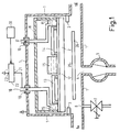
- a cathode sputtering device shown in section in FIG. 1 for coating the surfaces of objects has a vacuum chamber 1 in which a target cathode 2 and an anode 3 are arranged.
- the vacuum chamber 1 is completely airtight and can be evacuated from air by means of a pump 5 connected to an opening 4.
- Noble gas is supplied to the chamber 1 from the outside via a second opening 6 via a metering valve 7.
- the chamber has two openings 1a and 1b which lead to the outside and are introduced into the chamber through the objects which are not shown in the figure, and through which the objects are brought out again after coating.
- the openings 1a and 1b open into tubular extensions which, like the chamber 1 itself, are also airtight in the manner not shown in the figure.
- the anode 3 extends in a ring shape in the vacuum chamber 1, while the cathode 2 extends in an upper region of the chamber 1 provided electrically conductive holder 11 is arranged inside the chamber.
- the target cathode 2 is connected to the holder 11 via a rear plate 12.
- Two arrangements 13 and 14 for generating a magnetic field are provided in the holder 11 above the back plate 12 of the target cathode 2.
- the magnetic fields point with their north or south poles to the back plate 12 and extend approximately parallel to the target cathode in partial areas thereof.
- cooling channels 15 are provided in the holder, through which a cooling liquid flows. The cooling liquid is fed to the channels via a pipe 16 and discharged through a pipe 17.
- the tubes 16 and 17 are led out of the chamber 1 through seals 18 and 19. At least the seal 18 is designed so that it has an electrically insulating effect between the tube 16 and the wall of the chamber 1. Furthermore, at least the tube 16, if desired also the tube 17, is designed to be electrically conductive.
- the cathode 2 is connected to a negative pole 21 of a voltage source 22 via the back plate 12 and the tube 16, which is electrically conductively connected to the back plate 12 via at least one of the cooling channels 15.
- a positive pole 23 of the voltage source 22 is connected to ground.
- the anode 3 arranged in the chamber 1 is also connected to ground.
- the voltage source 22 can be controlled by an evaluation unit 30, which receives measurement signals from a probe in a manner not shown in the figure. The detailed functional description of the evaluation electronics 30 and the probe, not shown in the figure, will be made with reference to FIGS. 3 to 5.
- the function of the cathode sputtering device shown in FIG. 1 is as follows: A voltage which is positive with respect to the anode 3 is applied to the target cathode 2 by means of the voltage source 22.
- the target cathode and the anode are located in the vacuum chamber 1 filled with an inert gas. When a suitable voltage is applied, plasma discharges of the inert gas take place between these two electrodes. These plasma discharges are concentrated on the area of the target cathode by means of the magnet arrangements 13 and 14.
- the positive ions of the gas thereby increasingly hit the surface of the target cathode 2 and detach particles of the metal from which it is made. These metal particles are deposited on a surface 35 of a planar object 36 shown in section in FIG. 1.
- the surface 35 of the object 36 is coated with a thin layer, which consists of the material of the target cathode 2.
- the parameters for setting the intensity of the plasma discharges are the gas pressure, the voltage applied between the electrodes and, if appropriate, the strength of the magnetic field.
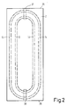
- FIG. 2 shows the target electrode 2 according to FIG. 1 in a top view from the anode side.
- the target cathode 2 has an approximately rectangular shape.
- the magnetic field arrangements 13 and 14 are also shown schematically in the top view of FIG. 2. These magnetic field arrangements run in the form of an oval. In the example shown in FIG. 2, the magnetic field arrangements run in the head regions 35 and 36 of the target cathode in a relatively small radius, so that a relatively strong magnetic field is formed in these regions. For this reason, the material of the target cathode is removed relatively strongly in these areas. It therefore makes sense to arrange a probe for measuring a critical target removal in one or both of these areas. In the figure, two possible locations 37 and 38 of such probes are shown schematically.
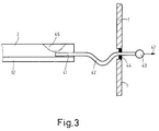
- a probe for measuring a critical target removal together with a target cathode is shown in section as a first embodiment.
- the target cathode 2 which can be of the type shown in FIGS. 1 and 2, for example, has a back plate 12 on its rear side.
- the target cathode itself can be made of aluminum, for example, and the back plate can be made of copper, for example.
- a bore 41 is made in the target cathode 2 shown in FIG. 3 in an area near the rear wall 12. This bore is connected to a pressure sensor 43 via a flexible, but gas-tight and electrically insulating hose 42.
- the hose 42 is guided through a seal 44.
- the seal 44 is in turn connected in a wall of the chamber of a sputtering device, which can be, for example, the chamber 1 shown in FIG. 1.
- a sputtering device which can be, for example, the chamber 1 shown in FIG. 1.
- Both the bore 41 in the target cathode and the tube 42 are filled with a gas. This gas pressure is measured by the pressure sensor 43.
- a possible removal 46 is entered in the figure as an example in the target cathode 2. When this removal 46 reaches the bore 41, the gas under pressure in the bore 41 and the hose 42 escapes through this opening. As a result, the pressure in the system drops, which is reported by the pressure sensor 43. This can be done, for example, in such a way that the pressure sensor 43 sends an electrical signal to an evaluation electronics 30, shown schematically in FIG. 1, which in turn interrupts the voltage applied to the electrodes 3 and 2.
- a probe can also be inserted into such a bore, which in turn is connected to the pressure sensor via a hose and which has a chamber which is filled with a gas.
- the probe must then consist of the same material as the target cathode.
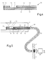
- FIG. 4 shows a second embodiment of a probe for measuring a critical target removal in section.
- This embodiment is an electrically working probe 50.
- a measuring line 51 is arranged inside the probe 50.
- the measuring line 51 is surrounded by a ceramic tube 52 and this in turn is surrounded by a metal tube 53.
- the first 4 At its first end 54, the first 4, the measuring line 51, the ceramic tube 52 and the metal tube 53 are closed off with an electrically insulating cover 55 into a bore or groove of a target cathode (not shown in FIG. 4).
- This cover 55 can be glued with ceramic adhesive, for example.
- the ceramic tube 52 and the metal tube 53 are open in a semi-cylindrical region 56. In the installed state, this region 56 points to the side of the target cathode which is being removed.
- FIG. 5 In which the probe shown in FIG. 4 working in an electrical manner and a target cathode, which can be, for example, the target cathode 2 shown in FIGS. 1 and 2, are shown in section .
- the probe 50 is inserted into a bore 61 of the target cathode 2.
- the bore 61 is made in an area adjacent to the back plate 12.
- a possible removal 62 is shown as an example in the target cathode 2 in FIG. 5. This removal 62 is shown in the figure shortly before the breakthrough to the probe.
- the measuring line 51 in the probe is connected via an insulated cable 63 to evaluation electronics, which can be evaluation electronics 30 shown in FIG. 1, for example.
- the cable is guided through an insulated feedthrough 64.
- This insulated feedthrough 64 is located, for example, in a wall of the vacuum chamber 1 shown in FIG. 1.
- the measuring line 51 of the probe 50 is therefore connected to the evaluation electronics 30 via the cable connection 63.
- the evaluation electronics 30 measures the electrical potential at which the measuring line 51 lies.
- the removal 62 shown schematically in the figure reaches the open area 55 reached the probe, the measuring line is in contact with the positively charged discharge plasma.
- This is registered by the evaluation electronics 30 as a result of a changing electrical potential of the measuring line 51 connected to the evaluation electronics 30 via the cable connection 63, and a corresponding signal 65 is given to the outside, which can serve, for example, to supply the voltage to the Interrupt electrodes of the sputtering device.
- the measuring line could also be a resistance wire, which changes its terminating resistance to the measuring electronics 30 as soon as it melts.
Landscapes
- Chemical & Material Sciences (AREA)
- Engineering & Computer Science (AREA)
- Chemical Kinetics & Catalysis (AREA)
- Materials Engineering (AREA)
- Mechanical Engineering (AREA)
- Metallurgy (AREA)
- Organic Chemistry (AREA)
- Physics & Mathematics (AREA)
- Plasma & Fusion (AREA)
- Analytical Chemistry (AREA)
- Physical Vapour Deposition (AREA)
- Measuring Fluid Pressure (AREA)
Description
Die Erfindung bezieht sich auf eine Kathodenzerstäubungseinrichtung zum Beschichten der Oberflächen von Gegenständen, in der eine Vakuum-Kammer vorgesehen ist, die ein Edelgas enthält, und in der eine Target-Kathode und eine Anode angeordnet sind, an die zur Erzeugung von Plasmaentladungen eine Spannung angelegt ist, wobei ein Magnetfeld, das die Plasmaentladungen intensiviert und auf den Bereich der Target-Kathode konzentriert, und eine Einrichtung zur Messung des Target-Abtrages vorgesehen sind.The invention relates to a cathode sputtering device for coating the surfaces of objects, in which a vacuum chamber is provided, which contains a noble gas, and in which a target cathode and an anode are arranged, to which a voltage is applied in order to generate plasma discharges is, a magnetic field, which intensifies the plasma discharges and concentrates on the area of the target cathode, and a device for measuring the target removal are provided.
In derartigen Kathodenzerstäubungseinrichtungen wird das Material der Target-Kathode abgetragen und schlägt sich unter anderem auch auf den Oberflächen der zu beschichtenden Gegenstände nieder. Aus diesem Grunde ist es wünschenswert, den Abtrag der Target-Kathode zu messen bzw. vor deren völligem Abtrag ein Alarmsignal zu erhalten. Ein völliger Abtrag der Target-Kathode ist nicht wünschenswert, da in diesem Falle deren Rückplatte bzw. Teile der Kathodenzerstäubungseinrichtung mitzerstäubt und beschädigt werden.In such cathode sputtering devices, the material of the target cathode is removed and, among other things, is deposited on the surfaces of the objects to be coated. For this reason, it is desirable to measure the removal of the target cathode or to receive an alarm signal before it is completely removed. A complete removal of the target cathode is not desirable, since in this case the back plate or parts of the cathode sputtering device are sputtered and damaged.
Es ist bei derartigen Anlagen bekannt, den Abtrag der Target-Kathode indirekt zu messen. Dies kann z.B. durch Messung der elektrischen Impedanz der Kathoden-Anodenanordnung, durch Messung der Target-Temperatur oder auch durch Messung der Veränderung des Magnetfeldes geschehen. So ist beispielsweise aus der DE-OS 34 25 659 ein Verfahren zum Regeln einer Sputter-Beschichtungseinrichtung bekannt, bei dem bestimmte Meßgrößen mit vorgegebenen Werten verglichen werden, um festzustellen, ob das Target so weit erodiert wurde, daß eine Verstellung der Plasma-Parameter erforderlich ist, oder das Target als verbraucht angesehen werden muß. Als Meßgrößen werden dabei eingestellte Arbeitspunkte für die Spannung und den Strom des Plasmas und für das magnetische Feld eingesetzt. Es wird hier also die Impedanz der Kathoden-Anodenanordnung bzw. eine Veränderung des Magnetfeldes gemessen. Ferner ist aus der DE-OS 34 25 344 eine Magnetron-Sputter-Beschichtungsquelle bekannt, bei der mittels einer in der Nähe der Target-Kathode vorgesehenen Hall-Sonde das Magnetfeld abgetastet wird. Aus der Änderung des Magnetfeldes werden Rückschlüsse auf den Target-Abtrag gezogen. Aus der DD-PS 220 618 ist eine Schaltungsanordnung zur Target-Verschleißbestimmung in Sputter-Anlagen bekannt, bei der eine Gleichspannungsmeßgröße eingesetzt wird, die abhängig ist von der vom Plasmatron aufgenommenen Leistung. Auf diese Weise kann über die aufgenommene Leistung des Plasmatrons ein Rückschluß auf den Abtrag der Target-Kathode gezogen werden. Allen diesen Verfahren ist jedoch gemeinsam, daß sie lediglich eine indirekte Messung ermöglichen und so keine präzise Messung des Abtrags der Target-Kathode liefern können. Außerdem liefern diese Verfahren gewissermaßen nur ein statistisches Mittel des Abtrages und lassen so keine Rückschlüsse darauf zu, ob das Material an einer Stelle möglicherweise schon völlig oder fast völlig abgetragen ist.In such systems, it is known to indirectly measure the removal of the target cathode. This can be done, for example, by measuring the electrical impedance of the cathode-anode arrangement, by measuring the target temperature or by measuring the change in the magnetic field. For example, from DE-OS 34 25 659 a method for controlling a sputter coating device is known, in which certain measured variables are compared with predetermined values in order to determine whether the target has been eroded to such an extent that an adjustment of the plasma parameters is necessary is, or the target must be considered used up. Set working points for the voltage and current of the plasma and for the magnetic field are used as measured variables. The impedance of the cathode-anode arrangement or a change in the magnetic field is therefore measured here. Furthermore, a magnetron sputter coating source is known from DE-OS 34 25 344, in which the magnetic field is scanned by means of a Hall probe provided in the vicinity of the target cathode. The change in the magnetic field allows conclusions to be drawn about the target removal. From DD-PS 220 618 a circuit arrangement for target wear determination in sputter systems is known, in which a DC voltage measurement variable is used, which is dependent on the power consumed by the plasmatron. In this way, conclusions can be drawn about the removal of the target cathode from the power consumed by the plasmatron. However, all these methods have in common that they only allow indirect measurement and thus no precise measurement of the removal of the Can deliver target cathode. In addition, these methods provide, so to speak, only a statistical mean of the removal and thus do not allow any conclusions to be drawn as to whether the material has possibly already been completely or almost completely removed.
Aus der europäischen Patentanmeldung 0 046 154 ist es ferner bekannt, in einer Kathodenzerstäubungseinrichtung hinter der Target-Kathode eine abgeschlossene Kammer vorzusehen, welche mit einem unter Druck stehenden Gas gefüllt ist. Der Druck des Gases in der Kammer wird gemessen und bei einem Abfall des Druckes Alarm gegeben bzw. die Anlage abgeschaltet, da die Target-Kathode dann an wenigstens einer Stelle völlig abgetragen ist. Diese Anordnung hat jedoch den Nachteil, daß über den Abtrag des Targets erst dann eine Aussage gemacht werden kann, wenn dieser an wenigstens einer Stelle schon völlig abgetragen ist. Ein Einsatz dieses Verfahrens ist daher insbesondere in solchen Fällen nicht möglich, in denen es auf besondere Reinheit der Beschichtung ankommt. In diesen Fällen darf eine an der Target-Kathode im allgemeinen vorgesehenen Rückplatte nicht mitzerstäubt werden. Darüber hinaus erfordert die gasdichte Kammer einen sehr hohen konstruktiven Aufwand der Anlage.From European patent application 0 046 154 it is also known to provide a closed chamber in a sputtering device behind the target cathode, which chamber is filled with a gas under pressure. The pressure of the gas in the chamber is measured and an alarm is given if the pressure drops, or the system is switched off, since the target cathode is then completely removed at at least one point. However, this arrangement has the disadvantage that a statement about the removal of the target can only be made if it has already been completely removed at least at one point. It is therefore not possible to use this method, in particular, in cases in which the coating is particularly clean. In these cases, a backplate generally provided on the target cathode must not be sputtered. In addition, the gas-tight chamber requires a very high level of design complexity for the system.
Es ist Aufgabe der Erfindung, bei einer Kathodenzerstäubungseinrichtung der eingangs genannten Art eine Vorrichtung anzugeben, welche einen kritischen Abtrag des Materials der Target-Kathode zuverlässig bereits vor dem völligen Abtrag des Materials angibt und die darüber hinaus einfach zu verwirklichen ist.It is an object of the invention to provide in a cathode sputtering device of the type mentioned at the outset a device which reliably indicates a critical removal of the material of the target cathode before the complete removal of the material and which is also easy to implement.
Diese Aufgabe wird erfindungsgemäß dadurch gelöst, daß zur Messung eines kritischen Target-Abtrages in der Target-Kathode wenigstens eine Sonde vorgesehen ist, die bei bis auf die Sonde abgetragenem Target-Material anspricht.This object is achieved in that at least one probe is provided for measuring a critical target removal in the target cathode, which probe responds to target material that has been removed down to the probe.
In der Target-Kathode wird, beispielsweise in einer Bohrung oder Nut, eine Sonde eingebracht, welche signalisiert, daß das sie umgebende Target-Material auf wenigstens einer Seite völlig abgetragen ist. Die Sonde wird in der Target-Kathode in der Weise positioniert, daß sie sicher bereits vor dem völligen Abtrag des Materials anspricht. Die Sonde wird also im allgemeinen im Bereich der Rückwand der Target-Kathode angebracht werden. Wird die Sonde an einer Stelle angebracht, die bevorzugt einem Abtrag ausgesetzt ist, so kann auf diese Weise mit einfachen Mitteln vor Erreichen eines völligen Abtrages der Target-Kathode an einer beliebigen Stelle ein Alarmsignal erhalten werden, welches angibt, daß die Target-Kathode kurz vor ihrem völligen Abtrag steht. Dies ist von besonderer Bedeutung, da jede Stillstandszeit einer Kathodenzerstäubungseinrichtung unwirtschaftlich ist. Die Einrichtung nach der Erfindung bietet so die Möglichkeit, unnötige Stillstandszeiten zu vermeiden. Gleichzeitig ist das Risiko eines völligen Abtrages der Target-Kathode beseitigt, was insbesondere bei hohen Anforderungen an die Reinheit der Beschichtung der zu beschichtenden Oberflächen von Bedeutung ist.A probe is introduced into the target cathode, for example in a bore or groove, which signals that the target material surrounding it has been completely removed on at least one side. The probe is positioned in the target cathode in such a way that it will respond before the material is completely removed. The probe will therefore generally be attached in the area of the rear wall of the target cathode. If the probe is attached to a location which is preferably exposed to removal, an alarm signal can be obtained in this way with simple means before the target cathode has been completely removed at any location, indicating that the target cathode is short stands before their complete removal. This is of particular importance since any downtime of a cathode sputtering device is uneconomical. The device according to the invention thus offers the possibility of avoiding unnecessary downtimes. At the same time, the risk of complete removal of the target cathode is eliminated, which is particularly important when the requirements for the cleanliness of the coating of the surfaces to be coated are high.
Nach einer weiteren Ausgestaltung der Erfindung ist vorgesehen, daß die Sonde ein unter Druck stehendes Gas enthält, dessen Druckabfall den kritischen Targetabtrag markiert.According to a further embodiment of the invention, it is provided that the probe contains a gas under pressure, the pressure drop of which marks the critical target removal.
Die Sonde zur Markierung des kritischen Target-Abtrages kann beispielsweise aus einem Rohr bestehen, welches ein unter Druck stehendes Gas enthält. Der Druck dieses Gases wird registriert. Ein Druckabfall des Gases signalisiert sofort, daß die Sonde undicht geworden ist durch das Abtragen des sie umgebenden Materials der Target-Kathode und das damit verbundene Undichtwerden.The probe for marking the critical target removal can consist, for example, of a tube which contains a gas under pressure. The pressure of this gas is registered. A pressure drop in the gas immediately signals that the probe has become leaky due to the removal of the surrounding material of the target cathode and the associated leakage.
Nach einer weiteren Ausgestaltung der Erfindung ist vorgesehen, daß in der Sonde eine Kammer vorgesehen ist, die über eine druckdichte Schlauchverbindung mit einem Druckschalter verbunden ist, und daß die Kammer und der Schlauch mit einem Gas gefüllt sind, so daß der Druckschalter bei einem Druckabfall des Gases in Folge Erreichen des kritischen Target-Abtrages anspricht.According to a further embodiment of the invention, it is provided that a chamber is provided in the probe, which is connected to a pressure switch via a pressure-tight hose connection, and that the chamber and the hose are filled with a gas, so that the pressure switch when the pressure drops Gases in response to reaching the critical target removal.
Die Messung des Drucks des in der Sonde befindlichen Gases kann auf diese Weise mit einfachsten Mitteln vorgenommen werden. Bei einem Ansprechen des Druckschalters kann ein Alarmsignal gegeben werden; es kann aber auch die Kathodenzerstäubungseinrichtung unmittelbar abgeschaltet werden.The measurement of the pressure of the gas in the probe can be carried out in this way with the simplest of means. If the pressure switch responds, an alarm signal can be given; however, the cathode sputtering device can also be switched off immediately.
Nach einer weiteren Ausgestaltung der Erfindung ist vorgesehen, daß in der Target-Kathode eine Bohrung vorgesehen ist, die über eine druckdichte Schlauchverbindung mit einem Druckschalter verbunden ist und daß die Bohrung und der Schlauch mit einem unter Druck stehenden Gas gefüllt sind, so daß der Druckschalter bei einem Druckabfall des Gases in Folge des Erreichens des kritischen Target-Abtrages anspricht.According to a further embodiment of the invention, it is provided that a bore is provided in the target cathode, which is connected to a pressure switch via a pressure-tight hose connection, and that the bore and the hose are filled with a gas under pressure, so that the pressure switch in the event of a pressure drop in the gas as a result of reaching the critical target removal.
Die Sonde kann im einfachsten Falle aus einer einfachen Bohrung in der Target-Kathode bestehen, welche über eine druckdichte Schlauchverbindung mit einem Druckschalter verbunden ist. Ist das die Bohrung umgebende Material der Target-Kathode an einer Stelle abgetragen, entweicht das Gas und der Druckschalter spricht an. Auf diese Weise ist bei einfachstem konstruktiven Aufwand dennoch ein sicheres Messen eines kritischen Target-Abtrages möglich.In the simplest case, the probe can consist of a simple hole in the target cathode, which is connected to a pressure switch via a pressure-tight hose connection. If the material of the target cathode surrounding the bore is removed at one point, the gas escapes and the pressure switch responds. In this way, a reliable measurement of a critical target removal is still possible with the simplest design effort.
Nach einer weiteren Ausgestaltung der Erfindung ist vorgesehen, daß die Sonde eine elektrisch leitfähige Meßleitung aufweist, deren Kontakt mit dem Entladungsplasma elektronisch ausgewertet wird.According to a further embodiment of the invention it is provided that the probe has an electrically conductive measuring line, the contact of which with the discharge plasma is electronically evaluated.
Neben der Möglichkeit der Messung des Druckes eines in der Sonde vorgesehenen Gases besteht auch die Möglichkeit, in der Sonde eine elektrisch leitfähige Meßleitung vorzusehen, deren Kontakt mit dem Entladungsplasma infolge des Erreichens des kritischen Target-Abtrages elektronisch ausgewertet wird. In diesem Falle ist es nur noch erforderlich, die Meßleitung mit einer im allgemeinen außerhalb der Kammer angeordneten Auswerteelektronik zu verbinden. Die Auswertung des elektrischen Potentials der Meßleitung kann auf folgende Art und Weise vorgenommen werden. Bei Erreichen des kritischen Target-Abtrages, d. h. also, wenn das Target-Material bis auf die Sonde abgetragen ist, strömt das Entladungsplasma in die Meßsonde ein und umgibt auch die Meßleitung. Die Ionen des Plasmas sind positiv geladen und beeinflussen das elektrische Potential der Meßleitung entsprechend. Diese Veränderung des Potentials der Meßleitung wird durch die Auswerte-Elektronik erkannt, die daraufhin ein entsprechendes Signal gibt.In addition to the possibility of measuring the pressure of a gas provided in the probe, there is also the possibility of providing an electrically conductive measuring line in the probe, the contact of which with the discharge plasma is electronically evaluated as a result of reaching the critical target removal. In this case, it is only necessary to connect the measuring line to evaluation electronics which are generally arranged outside the chamber. The electrical potential of the measuring line can be evaluated in the following manner. When the critical target removal is reached, that is to say when the target material has been removed down to the probe, the discharge plasma flows into the measuring probe and also surrounds the measuring line. The ions in the plasma are positively charged and influence the electrical potential of the measuring line accordingly. This change in the potential of the measuring line is recognized by the evaluation electronics, which then give a corresponding signal.
Noch einer weiteren Ausgestaltung der Erfindung ist vorgesehen, daß die Meßleitung in einem Keramikrohr verläuft, das wiederum mit einem Metallrohr ummantelt ist, und daß beide Rohre in einem Teilbereich zu einer Seite hin geöffnet sind, so daß die Meßleitung in diesem Bereich zum abzutragenden Target-Material freiliegt.Yet another embodiment of the invention provides that the measuring line runs in a ceramic tube, which is in turn encased in a metal tube, and that both tubes are open to one side in a partial area, so that the measuring line in this area leads to the target to be removed. Material is exposed.
Es hat sich als vorteilhaft erwiesen, die Meßleitung in einem Keramikrohr anzuordnen, da dieses elektrisch isolierend wirkt. Das Keramikrohr ist wiederum von einem Metallrohr umgeben. Beide Rohre sind in einem Teilbereich zu der abzutragenden Seite der Target-Kathode hin geöffnet. Ist das Material der Target-Kathode bis auf diesen Bereich abgetragen, so gerät die Meßleitung in elektrischen Kontakt mit dem Entladungsplasma, was, wie oben beschrieben, elektronisch ausgewertet werden kann.It has proven to be advantageous to arrange the measuring line in a ceramic tube, since this has an electrically insulating effect. The ceramic tube is in turn surrounded by a metal tube. Both tubes are open in a partial area to the side of the target cathode to be removed. If the material of the target cathode is removed up to this area, the measuring line comes into electrical contact with the discharge plasma, which, as described above, can be evaluated electronically.
Nach einer weiteren Ausgestaltung der Erfindung ist vorgesehen, daß die Sonde in dem Bereich der Target-Elektrode angeordnet ist, der am schnellsten abgetragen wird. Im allgemeinen ist der am schnellsten abgetragene Bereich der Target-Elektrode empirisch bekannt. In diesen Fällen bereitet es keine Probleme, eine oder mehrere Sonden in diesen Bereichen vorzusehen.According to a further embodiment of the invention it is provided that the probe is arranged in the area of the target electrode which is removed the fastest. In general, the most rapidly removed area of the target electrode is known empirically. In these cases there is no problem in providing one or more probes in these areas.
Nach einer weiteren Ausgestaltung der Erfindung ist vorgesehen, daß das Magnetfeld der Kathodenzerstäubungseinrichtung in einem definierten Bereich der TargetKathode stärker ist als in den übrigen Bereichen und daß die Sonde in diesem definierten Bereich angeordnet ist.According to a further embodiment of the invention it is provided that the magnetic field of the sputtering device is stronger in a defined area of the target cathode than in the other areas and that the probe is arranged in this defined area.
Ist kein genau definierter Bereich der Target-Kathode bekannt, der bevorzugt abgetragen wird, oder existiert kein solcher, so besteht die Möglichkeit, das Magnetfeld in einem bestimmten Bereich stärker vorzusehen als in den übrigen Bereichen. Dies hat zur Folge, daß das Material der Target-Kathode in diesem Bereich stärker als in den übrigen abgetragen wird. Die Sonde zur Messung des kritischen Target-Abtrages wird dann in diesem Bereich angebracht und gibt ein Erreichen des kritischen Target-Abtrages in diesem Bereich an, der in jedem Falle eher erreicht ist als in den übrigen Bereichen der Target-Kathode.If no precisely defined area of the target cathode is known, which is preferably removed or exists no such, there is the possibility of providing the magnetic field stronger in a certain area than in the other areas. The result of this is that the material of the target cathode is removed more strongly in this area than in the rest. The probe for measuring the critical target removal is then attached in this area and indicates that the critical target removal has been reached in this area, which in any case is reached sooner than in the other areas of the target cathode.
Nach einer weiteren Ausgestaltung der Erfindung ist vorgesehen, daß die aus dem abzutragenden Metall bestehende Target-Kathode mit einer aus einem anderen Metall bestehenden Rückplatte versehen ist und daß die Sonde in dem abzutragenden Metall in einem Grenzbereich zur Rückplatte angeordnet ist.According to a further embodiment of the invention, it is provided that the target cathode consisting of the metal to be removed is provided with a back plate made of another metal and that the probe is arranged in the metal to be removed in a border region to the back plate.
Im allgemeinen weist die aus dem abzutragenden Material bestehende Target-Kathode eine Rückplatte auf, die ebenfalls aus einem Metall besteht. In diesen Fällen ist es vorteilhaft, die Sonde in den Grenzbereichen zwischen den beiden Metallen vorzusehen. Dies wird im allgemeinen in der Weise geschehen, daß in dem abzutragenden Metall in einem zu der Rückplatte benachbarten Grenzbereich eine Bohrung vorgenommen wird, in die die Sonde eingeführt wird.In general, the target cathode made of the material to be removed has a back plate, which is also made of a metal. In these cases it is advantageous to provide the probe in the border areas between the two metals. This will generally be done by drilling a hole in the metal to be removed in a border area adjacent to the backplate into which the probe is inserted.
Die Erfindung wird nachstehend anhand einiger Ausführungsbeispiele näher erläutert. Es zeigen:
- Fig. 1
- eine Kathodenzerstäubungseinrichtung zum Beschichten der Oberflächen von Gegenständen in teilweiser Schnittdarstellung,
- Fig. 2
- eine Target-Kathode der Einrichtung nach Fig. 1 in Draufsicht,
- Fig. 3
- eine erste Ausführungsform einer Sonde in einer Target-Kathode in Schnittdarstellung,
- Fig. 4
- eine zweite Ausführungsform einer Sonde in Schnittdarstellung,
- Fig. 5
- den Schnitt durch eine Target-Kathode mit eingesetzter Sonde nach Fig. 4.
- Fig. 1
- a cathode sputtering device for coating the surfaces of objects in a partial sectional view,
- Fig. 2
- 2 is a top view of a target cathode of the device according to FIG. 1,
- Fig. 3
- 1 shows a first embodiment of a probe in a target cathode in a sectional view,
- Fig. 4
- A second embodiment of a probe in a sectional view,
- Fig. 5
- the section through a target cathode with inserted probe according to FIG. 4.
Eine in Fig. 1 im Schnitt dargestellte Kathodenzerstäubungseinrichtung zum Beschichten der Oberflächen von Gegenständen weist eine Vakuumkammer 1 auf, in der eine Target-Kathode 2 und eine Anode 3 angeordnet sind. Die Vakuumkammer 1 ist rundherum luftdicht abgeschlossen und mittels einer mit einer Öffnung 4 verbundenen Pumpe 5 von Luft evakuierbar. Uber eine zweite Öffnung 6 wird der Kammer 1 über ein Dosierventil 7 von außen Edelgas zugeführt Die Kammer weist zwei Öffnungen 1a und 1b auf, die nach außen führen und durch die in in der Figur nicht dargestellter Weise in die Kammer zu beschichtende Gegenstände hereingeführt werden und durch die die Gegenstände nach dem Beschichten wieder herausgeführt werden. Die Öffnungen 1a und 1b münden in rohrförmige Ausläufer, die in der in der Figur nicht dargestellter Weise ebenso wie auch die Kammer 1 selbst gegenüber der äußeren Atmosphäre luftdicht abgeschlossen sind. Die Anode 3 verläuft ringförmig in der Vakuumkammer 1, während die Kathode 2 an einer in einem oberen Bereich der Kammer 1 vorgesehen elektrisch leitfähigen Halterung 11 im Inneren der Kammer angeordnet ist. Die Target-Kathode 2 ist dazu über eine Rückplatte 12 mit der Halterung 11 verbunden. In der Halterung 11 sind oberhalb der Rückplatte 12 der Target-Kathode 2 zwei Anordnungen 13 und 14 zur Erzeugung eines Magnetfeldes vorgesehen. Die Magnetfelder weisen mit ihren Nord- bzw. Südpolen zu der Rückplatte 12 und verlaufen in Teilbereichen der Target-Kathode in etwa parallel zu dieser. Zwischen den Magnet-Anordnungen 13 und 14 sind in der Halterung 11 Kühlkanäle 15 vorgesehen, welche von einer Kihlflüssigkeit durchströmt werden. Die Kühlflüssigkeit wird den Kanälen über ein Rohr 16 zu- und ein Rohr 17 abgeführt. Die Rohre 16 und 17 sind durch Dichtungen 18 und 19 aus der Kammer 1 herausgeführt. Wenigstens die Dichtung 18 ist so ausgeführt, daß sie zwischen dem Rohr 16 und der Wand der Kammer 1 elektrisch isolierend wirkt. Ferner ist wenigstens das Rohr 16, gewünschtenfalls auch das Rohr 17, elektrisch leitfähig ausgeführt.A cathode sputtering device shown in section in FIG. 1 for coating the surfaces of objects has a vacuum chamber 1 in which a
Die Kathode 2 ist über die Rückplatte 12 und das Rohr 16, das über wenigstens einen der Kühlkanäle 15 elektrisch leitend mit der Rückplatte 12 verbunden ist, mit einem negativen Pol 21 einer Spannungsquelle 22 verbunden. Ein positiver Pol 23 der Spannungsquelle 22 ist mit Masse verbunden. Die in der Kammer 1 angeordnete Anode 3 ist ebenfalls mit Masse verbunden. Die Spannungsquelle 22 kann von einer Auswerteeinheit 30 angesteuert werden, welche in in der Figur nicht dargestellter Weise von einer Sonde Meßsignale erhält. Die nähere Funktionsbeschreibung der Auswerteelektronik 30 und der in der Figur nicht dargestellten Sonde wird anhand der Fig. 3 bis 5 vorgenommen werden.The
Die Funktion der in Fig. 1 dargestellten Kathodenzerstäubungseinrichtung ist folgende:
Mittels der Spannungsquelle 22 ist an die Target-Kathode 2 eine gegenüber der Anode 3 positive Spannung angelegt. Die Target-Kathode und die Anode befinden sich in der mit einem Edelgas gefüllten Vakuumkammer 1. Bei Anlegen einer geeigneten Spannung finden zwischen diesen beiden Elektroden Plasmaentladungen des Edelgases statt. Mittels der Magnet-Anordnungen 13 und 14 werden diese Plasmaentladungen auf den Bereich der Target-Kathode konzentriert. Die positiven Ionen des Gases treffen dadurch verstärkt auf die Oberfläche der Target-Kathode 2 und lösen aus ihr Teilchen des Metalles, aus dem sie besteht, heraus. Diese Metallteilchen schlagen sich auf einer Oberfläche 35 eines in der Fig. 1 im Schnitt dargestellten flächenhaften Gegenstandes 36 nieder. Auf diese Weise wird die Oberfläche 35 des Gegenstandes 36 mit einer dünnen Schicht beschichtet, die aus dem Material der Target-Kathode 2 besteht. Die Parameter zur Einstellung der Intensität der Plasmaentladungen sind der Gasdruck, die zwischen die Elektroden angelegte Spannung und gegebenenfalls die Stärke des Magnetfeldes.The function of the cathode sputtering device shown in FIG. 1 is as follows:
A voltage which is positive with respect to the
In Fig. 2 ist die Target-Elektrode 2 nach Fig. 1 in Draufsicht von der Anodenseite her dargestellt. Die Target-Kathode 2 hat in diesem Ausführungsbeispiel eine in etwa rechteckige Form. In der Draufsicht-Darstellung von Fig. 2 sind ebenfalls die Magnetfeld-Anordnungen 13 und 14 schematisch dargestellt. Diese Magnetfeld-Anordnungen verlaufen in Form eines Ovals. In dem in Fig. 2 dargestellten Beispiel verlaufen die Magnetfeldanordnungen in den Kopfbereichen 35 und 36 der Target-Kathode in einem relativ kleinen Radius, so daß sich in diesen Bereichen ein relativ starkes Magnetfeld ausbildet. Aus diesem Grunde wird das Material der Target-Kathode in diesen Bereichen relativ stark abgetragen. Es ist daher sinnvoll, eine Sonde zur Messung eines kritischen Target-Abtrages in einem oder in beiden dieser Bereiche anzuordnen. In der Figur sind zwei mögliche Anbringungsorte 37 und 38 solcher Sonden schematisch dargestellt. Im folgenden werden anhand der Fig. 3 bis 5 zwei Ausführungsbeispiele solcher Sonden näher erläutert, wie sie beispielsweise in einer Kathodenzerstäubungseinrichtung nach Fig. 1 bzw. einer Target-Kathode nach Fig. 1 und 2 eingesetzt werden können. Diese Sonden dienen dazu, beim Erreichen eines kritischen Target-Abtrages ein entsprechendes Signal an die in Fig. 1 schematisch dargestellte Auswerteeinheit 30 zu geben, welche wiederum die Spannungsquelle 22 ansteuert und damit die an die Elektroden angelegte Spannung rechtzeitig vor einem völligen Abtrag der Target-Kathode 2 abschaltet.FIG. 2 shows the
In Fig. 3 ist als erstes Ausführungsbeispiel eine Sonde zur Messung eines kritischen Target-Abtrages zusammen mit einer Target-Kathode im Schnitt dargestellt. Die Target-Kathode 2, die beispielsweise der in Fig. 1 und Fig. 2 dargestellten Bauart sein kann, trägt an ihrer Rückseite eine Rückplatte 12. Die Target-Kathode selbst kann beispielsweise aus Aluminium und die Rückplatte beispielsweise aus Kupfer bestehen. In die in Fig. 3 dargestellte Target-Kathode 2 ist in einem Bereich nahe der Rückwand 12 eine Bohrung 41 eingebracht. Diese Bohrung ist über einen flexiblen, jedoch gasdichten und elektrisch isolierenden Schlauch 42 mit einem Drucksensor 43 verbunden. Der Schlauch 42 ist durch eine Dichtung 44 geführt. Die Dichtung 44 ist ihrerseits in einer Wand der Kammer einer Kathodenzerstäubungseinrichtung verbunden, die beispielsweise die in Fig. 1 dargestellte Kammer 1 sein kann. Sowohl die Bohrung 41 in der Target-Kathode wie auch der Schlauch 42 sind mit einem Gas gefüllt. Dieser Gasdruck wird von dem Drucksensor 43 gemessen. In der Target-Kathode 2 ist in der Figur beispielhaft ein möglicher Abtrag 46 eingetragen. Erreicht dieser Abtrag 46 die Bohrung 41, so entweicht das in der Bohrung 41 und dem Schlauch 42 unter Druck stehende Gas durch diese entstandene Öffnung. Infolgedessen fällt der Druck in dem System ab, was durch den Drucksensor 43 gemeldet wird. Dies kann z.B. in der Weise geschehen, daß der Drucksensor 43 ein elektrisches Signal an eine in Fig. 1 schematisch dargestellte Auswerteelektronik 30 leitet, die wiederum die an die Elektroden 3 und 2 angelegte Spannung unterbricht.In Fig. 3, a probe for measuring a critical target removal together with a target cathode is shown in section as a first embodiment. The
Anstelle der in der Fig. 3 eingebrachten Bohrung 41 kann auch in eine solche Bohrung eine Sonde eingesteckt werden, welche wiederum über einen Schlauch mit dem Drucksensor verbunden ist und die eine Kammer aufweist, die mit einem Gas gefüllt ist. Dabei muß die Sonde dann aus dem gleichen Material bestehen wie die Target-Kathode.Instead of the
In Fig. 4 ist eine zweite Ausführungsform einer Sonde zur Messung eines kritischen Target-Abtrages im Schnitt dargestellt. Bei dieser Ausführungsform handelt es sich um eine elektrisch arbeitende Sonde 50 . Im Innern der Sonde 50 ist eine Meßleitung 51 angeordnet. Die Meßleitung 51 ist mit einem Keramikrohr 52 und dieses wiederum mit einem Metallrohr 53 umgeben. An ihrem ersten Ende 54, das zuerst in eine Bohrung bzw. Nut einer in der Fig. 4 nicht dargestellten Target-Kathode eingeführt wird, sind die Meßleitung 51, das Keramikrohr 52 und das Metallrohr 53 mit einem elektrisch isolierenden Deckel 55 abgeschlossen. Dieser Deckel 55 kann beispielsweise mit Keramikkleber verklebt sein. Das Keramikrohr 52 und das Metallrohr 53 sind in einem halbzylinderförmigen Bereich 56 offen. Dieser Bereich 56 zeigt im eingebauten Zustand zu der Seite der Target-Kathode hin, die abgetragen wird.4 shows a second embodiment of a probe for measuring a critical target removal in section. This embodiment is an electrically working
Dies ist in Fig. 5 näher dargestellt, in der die in Fig. 4 dargestellte auf elektrische Weise arbeitende Sonde und eine Target-Kathode, die beispielsweise die in den Fig. 1 und 2 dargestellte Target-Kathode 2 sein kann, im Schnitt dargestellt sind. Die Sonde 50 ist dabei in eine Bohrung 61 der Target-Kathode 2 eingeführt. Die Bohrung 61 ist in einem Bereich angebracht, der an die Rückplatte 12 angrenzt. In der Target-Kathode 2 ist in der Fig. 5 beispielhaft ein möglicher Abtrag 62 eingezeichnet. Dieser Abtrag 62 ist in der Figur kurz vor dem Durchbruch zur Sonde dargestellt. Die Meßleitung 51 in der Sonde ist über ein isoliertes Kabel 63 mit einer Auswerteelektronik verbunden, die beispielsweise die in Fig. 1 dargestellte Auswerteelektronik 30 sein kann. Dabei ist das Kabel durch eine isolierte Durchführung 64 geführt. Diese isolierte Durchführung 64 befindet sich beispielsweise in einer Wand der in Fig. 1 dargestellten Vakuumkammer 1. Die Meßleitung 51 der Sonde 50 ist also über die Kabelverbindung 63 mit der Auswerteelektronik 30 verbunden. Die Auswerte-Elektronik 30 mißt, auf welchemelektrischen Potential die Meßleitung 51 liegt. Sobald der in der Figur schematisch dargestellte Abtrag 62 den offenen Bereich 55 der Sonde erreicht, erhält die Meßleitung Kontakt mit dem positiv geladenen Entladungsplasma. Dies wird von der Auswerteelektronik 30 in Folge eines sich ändernden elektrischen Potentials der über die Kabelverbindung 63 mit der Auswerte-Elektronik 30 verbundenen Meßleitung 51 registriert, und es wird ein entsprechendes Signal 65 nach außen gegeben, das beispielsweise dazu dienen kann, die Spannungszuführung zu den Elektroden der Kathodenzerstäubungseinrichtung zu unterbrechen.This is shown in more detail in FIG. 5, in which the probe shown in FIG. 4 working in an electrical manner and a target cathode, which can be, for example, the
Neben dem in Fig. 5 dargestellten Beispiel sind weitere elektronisch arbeitende Ausführungen einer solchen Sonde möglich. Es könnte beispielsweise sich bei der Meßleitung auch um einen Widerstandsdraht handeln, der seinen Abschlußwiderstand gegenüber der Meßelektronik 30 verändert, sobald er durchschmilzt.In addition to the example shown in FIG. 5, further electronically working designs of such a probe are possible. For example, the measuring line could also be a resistance wire, which changes its terminating resistance to the measuring
Claims (11)
- A cathode-sputtering apparatus for coating surfaces of objects, having a vacuum chamber which contains an inert gas and in which a target cathode and an anode are arranged to which a voltage is applied to produce plasma discharges, a magnetic field, which intensifies the plasma discharges and concentrates them at the area of the target cathode, and a device for measuring the target consumption being provided, characterized in that for measuring a critical target consumption at least one probe is provided in the target cathode, which probe responds when the target material has eroded up to the probe.
- A cathode-sputtering apparatus as claimed in Claim 1, characterized in that the probe contains a gas, whose drop in pressure marks the critical target consumption.
- A cathode-sputtering apparatus as claimed in Claim 2, characterized in that the probe has a chamber, which is connected to a pressure switch via a pressure-tight tube connection, and in that the chamber and the tube are filled with a gas, so that the pressure switch is actuated in the case of a drop in gas pressure as a result of the critical target consumption being reached.
- A cathode-sputtering apparatus as claimed in Claim 2 or 3, characterized in that the material of the probe is the same as the material used for the target.
- A cathode-sputtering apparatus as claimed in Claim 2, characterized in that the probe comprises a part of the target cathode itself formed with a bore, which bore is connected to a pressure switch via a pressure-tight tube connection, and in that the bore and the tube are filled with a gas, so that the pressure switch is actuated in the case of a drop in gas pressure as a result of the critical target consumption being reached.
- A cathode-sputtering apparatus as claimed in Claim 1, characterized in that the probe comprises an electrically conductive measurement lead whose contact with the discharge plasma is detected electronically.
- A cathode-sputtering apparatus as claimed in Claim 6, characterized in that the measurement lead is arranged in a ceramic tube surrounded by a metal tube, and in that both tubes are locally open to one side, so that at this location the measurement lead borders on the target material to be removed.
- A cathode-sputtering apparatus as claimed in any one of the Claims 1 to 7, characterized in that the probe is arranged at the location with the highest rate of consumption of the target electrode.
- A cathode-sputtering apparatus as claimed in any one of the Claims 1 to 7, characterized in that in a specific area of the target cathode the magnetic field of the cathode-sputtering apparatus is stronger than in the other areas, and in that the probe is arranged in said specific area.
- A cathode-sputtering apparatus as claimed in any one of the Claims 1 to 9, characterized in that the target cathode, which is made of the metal to be deposited, is provided with a rear plate of another metal, and in that the probe is arranged in an area bordering on the rear plate in the metal to be deposited.
- A cathode-sputtering apparatus as claimed in Claim 10, characterized in that the metal to be deposited is aluminium, and in that the rear plate is made of copper.
Applications Claiming Priority (2)
| Application Number | Priority Date | Filing Date | Title |
|---|---|---|---|
| DE3630737A DE3630737C1 (en) | 1986-09-10 | 1986-09-10 | Cathode sputtering device with a device for measuring a critical target removal |
| DE3630737 | 1986-09-10 |
Publications (2)
| Publication Number | Publication Date |
|---|---|
| EP0259934A1 EP0259934A1 (en) | 1988-03-16 |
| EP0259934B1 true EP0259934B1 (en) | 1992-01-02 |
Family
ID=6309251
Family Applications (1)
| Application Number | Title | Priority Date | Filing Date |
|---|---|---|---|
| EP87201720A Expired - Lifetime EP0259934B1 (en) | 1986-09-10 | 1987-09-09 | Sputtering apparatus with a device for the measurement of a critical target depletion |
Country Status (6)
| Country | Link |
|---|---|
| US (1) | US5380419A (en) |
| EP (1) | EP0259934B1 (en) |
| JP (1) | JPS63121661A (en) |
| KR (1) | KR950001216B1 (en) |
| DE (2) | DE3630737C1 (en) |
| HK (1) | HK70494A (en) |
Families Citing this family (13)
| Publication number | Priority date | Publication date | Assignee | Title |
|---|---|---|---|---|
| CH669609A5 (en) * | 1986-12-23 | 1989-03-31 | Balzers Hochvakuum | |
| EP0401622B1 (en) * | 1989-06-05 | 1995-08-23 | Balzers Aktiengesellschaft | Target cooling procedure and device for cooling targets |
| DE4022461A1 (en) * | 1990-07-14 | 1992-01-23 | Leybold Ag | SPRAYING CATHODE |
| EP0615273A1 (en) * | 1993-03-12 | 1994-09-14 | Applied Materials, Inc. | Method and apparatus for detection of sputtering target erosion |
| JPH08176808A (en) * | 1993-04-28 | 1996-07-09 | Japan Energy Corp | Sputtering target with life alarming function |
| TW200419139A (en) * | 2002-09-12 | 2004-10-01 | Honeywell Int Inc | Sensor system and methods used to detect material wear and surface deterioration |
| US6811657B2 (en) * | 2003-01-27 | 2004-11-02 | Micron Technology, Inc. | Device for measuring the profile of a metal film sputter deposition target, and system and method employing same |
| US20060081459A1 (en) * | 2004-10-18 | 2006-04-20 | Applied Materials, Inc. | In-situ monitoring of target erosion |
| US20060171848A1 (en) * | 2005-01-31 | 2006-08-03 | Advanced Energy Industries, Inc. | Diagnostic plasma sensors for endpoint and end-of-life detection |
| US8795486B2 (en) * | 2005-09-26 | 2014-08-05 | Taiwan Semiconductor Manufacturing Company, Ltd. | PVD target with end of service life detection capability |
| US20070068796A1 (en) * | 2005-09-26 | 2007-03-29 | Taiwan Semiconductor Manufacturing Co., Ltd. | Method of using a target having end of service life detection capability |
| US7891536B2 (en) | 2005-09-26 | 2011-02-22 | Taiwan Semiconductor Manufacturing Co., Ltd. | PVD target with end of service life detection capability |
| DE102010052341B4 (en) * | 2010-11-25 | 2015-02-12 | Von Ardenne Gmbh | Protection device on pipe targets |
Family Cites Families (14)
| Publication number | Priority date | Publication date | Assignee | Title |
|---|---|---|---|---|
| US4172020A (en) * | 1978-05-24 | 1979-10-23 | Gould Inc. | Method and apparatus for monitoring and controlling sputter deposition processes |
| US4324631A (en) * | 1979-07-23 | 1982-04-13 | Spin Physics, Inc. | Magnetron sputtering of magnetic materials |
| EP0046154B1 (en) * | 1980-08-08 | 1984-11-28 | Battelle Development Corporation | Apparatus for coating substrates by high-rate cathodic sputtering, as well as sputtering cathode for such apparatus |
| DE3047113A1 (en) * | 1980-12-13 | 1982-07-29 | Leybold-Heraeus GmbH, 5000 Köln | Cathode arrangement and control method for cathode sputtering systems with a magnet system for increasing the sputtering rate |
| US4379040A (en) * | 1981-01-29 | 1983-04-05 | Ppg Industries, Inc. | Method of and apparatus for control of reactive sputtering deposition |
| US4407708A (en) * | 1981-08-06 | 1983-10-04 | Eaton Corporation | Method for operating a magnetron sputtering apparatus |
| JPS5881968A (en) * | 1981-11-06 | 1983-05-17 | Hitachi Ltd | Method for correcting and controlling film thickness in film forming apparatus |
| CA1242989A (en) * | 1983-07-19 | 1988-10-11 | Donald R. Boys | Apparatus for and method of controlling sputter coating |
| NL8402012A (en) * | 1983-07-19 | 1985-02-18 | Varian Associates | MICROWAVE SPETTER COATING APPLICATION SOURCE FOR BOTH MAGNETIC AND NON-MAGNETIC TARGET MATERIALS. |
| US4545882A (en) * | 1983-09-02 | 1985-10-08 | Shatterproof Glass Corporation | Method and apparatus for detecting sputtering target depletion |
| GB2149034A (en) * | 1983-11-12 | 1985-06-05 | Hazel Grove Jig & Tool Co Limi | Brake pad wear indicator |
| DD220618A1 (en) * | 1984-01-09 | 1985-04-03 | Mikroelektronik Zt Forsch Tech | CIRCUIT ARRANGEMENT FOR TARGET CARRIER DETERMINATION IN SPUTTER UNITS |
| CA1253779A (en) * | 1984-06-11 | 1989-05-09 | Robert L. Dobson | Safety support system and method of making |
| DE8419083U1 (en) * | 1984-06-26 | 1985-10-24 | Textar Gmbh, 5090 Leverkusen | Display device for friction linings of disc brakes for motor vehicles |
-
1986
- 1986-09-10 DE DE3630737A patent/DE3630737C1/en not_active Expired
-
1987
- 1987-09-09 EP EP87201720A patent/EP0259934B1/en not_active Expired - Lifetime
- 1987-09-09 DE DE8787201720T patent/DE3775667D1/en not_active Expired - Lifetime
- 1987-09-10 KR KR1019870010025A patent/KR950001216B1/en active IP Right Grant
- 1987-09-10 JP JP62225413A patent/JPS63121661A/en active Pending
-
1993
- 1993-05-05 US US08/057,204 patent/US5380419A/en not_active Expired - Fee Related
-
1994
- 1994-07-21 HK HK70494A patent/HK70494A/en unknown
Also Published As
| Publication number | Publication date |
|---|---|
| EP0259934A1 (en) | 1988-03-16 |
| DE3630737C1 (en) | 1987-11-05 |
| KR880004130A (en) | 1988-06-01 |
| HK70494A (en) | 1994-07-29 |
| DE3775667D1 (en) | 1992-02-13 |
| US5380419A (en) | 1995-01-10 |
| KR950001216B1 (en) | 1995-02-14 |
| JPS63121661A (en) | 1988-05-25 |
Similar Documents
| Publication | Publication Date | Title |
|---|---|---|
| DE3724937C2 (en) | ||
| EP0259934B1 (en) | Sputtering apparatus with a device for the measurement of a critical target depletion | |
| DE3211229C2 (en) | ||
| DE4106770C2 (en) | Performing reactive coating of a substrate | |
| EP0416241B1 (en) | Apparatus for coating a substrate | |
| DE2556607C2 (en) | Method and device for cathode sputtering | |
| DE4441206A1 (en) | Device for the suppression of rollovers in cathode sputtering devices | |
| DE69919771T2 (en) | Vacuum-insulated switchgear | |
| DE3116732C2 (en) | High frequency discharge sputter etching device | |
| DE4420951C2 (en) | Device for detecting micro-flashovers in atomizing systems | |
| DE1515295B1 (en) | Device for applying thin layers of the material of a sputtering cathode to a support arranged perpendicular to an anode | |
| DE112013000459B4 (en) | wiring method | |
| DE4239218C2 (en) | Arrangement for preventing flashovers in a plasma process room | |
| EP0316523A2 (en) | Control for sputtering according to the magnetron principle | |
| DE10243634B4 (en) | Cold cathode ionization | |
| EP1566827A1 (en) | Magnetron sputtering apparatus | |
| DE2500161C2 (en) | ||
| DE4136655C2 (en) | Device for reactive coating of a substrate | |
| WO1990010947A1 (en) | Process for detecting the attainment of a predetermined depth in target body erosion and target body therefor | |
| EP0254168A2 (en) | Sputtering cathode for vaccum coating devices | |
| DE4301188C2 (en) | Device for coating or etching substrates | |
| DE2743954C2 (en) | Circuit arrangement for measuring the flow of a liquid containing electrical charges | |
| DD285463A5 (en) | METHOD FOR REGULATING THE BURNING FLASH POSITION ON A VACUUM BOW EVAPORATOR | |
| DE19540434C1 (en) | Analysis device for non-conductive material sample using HF glow discharge | |
| EP0467012A1 (en) | Cathode for sputtering |
Legal Events
| Date | Code | Title | Description |
|---|---|---|---|
| PUAI | Public reference made under article 153(3) epc to a published international application that has entered the european phase |
Free format text: ORIGINAL CODE: 0009012 |
|
| AK | Designated contracting states |
Kind code of ref document: A1 Designated state(s): CH DE ES FR GB IT LI |
|
| 17P | Request for examination filed |
Effective date: 19880902 |
|
| 17Q | First examination report despatched |
Effective date: 19900206 |
|
| GRAA | (expected) grant |
Free format text: ORIGINAL CODE: 0009210 |
|
| AK | Designated contracting states |
Kind code of ref document: B1 Designated state(s): CH DE ES FR GB IT LI |
|
| PG25 | Lapsed in a contracting state [announced via postgrant information from national office to epo] |
Ref country code: IT Free format text: LAPSE BECAUSE OF FAILURE TO SUBMIT A TRANSLATION OF THE DESCRIPTION OR TO PAY THE FEE WITHIN THE PRE;WARNING: LAPSES OF ITALIAN PATENTS WITH EFFECTIVE DATE BEFORE 2007 MAY HAVE OCCURRED AT ANY TIME BEFORE 2007. THE CORRECT EFFECTIVE DATE MAY BE DIFFERENT FROM THE ONE RECORDED.SCRIBED TIME-LIMIT Effective date: 19920102 |
|
| REF | Corresponds to: |
Ref document number: 3775667 Country of ref document: DE Date of ref document: 19920213 |
|
| PG25 | Lapsed in a contracting state [announced via postgrant information from national office to epo] |
Ref country code: ES Free format text: LAPSE BECAUSE OF FAILURE TO SUBMIT A TRANSLATION OF THE DESCRIPTION OR TO PAY THE FEE WITHIN THE PRESCRIBED TIME-LIMIT Effective date: 19920413 |
|
| GBT | Gb: translation of ep patent filed (gb section 77(6)(a)/1977) | ||
| ET | Fr: translation filed | ||
| PG25 | Lapsed in a contracting state [announced via postgrant information from national office to epo] |
Ref country code: LI Effective date: 19920930 Ref country code: CH Effective date: 19920930 |
|
| PLBE | No opposition filed within time limit |
Free format text: ORIGINAL CODE: 0009261 |
|
| STAA | Information on the status of an ep patent application or granted ep patent |
Free format text: STATUS: NO OPPOSITION FILED WITHIN TIME LIMIT |
|
| 26N | No opposition filed | ||
| REG | Reference to a national code |
Ref country code: CH Ref legal event code: AUV Free format text: DAS OBENGENANNTE PATENT IST, MANGELS BEZAHLUNG DER 6. JAHRESGEBUEHR, GELOESCHT WORDEN. Ref country code: CH Ref legal event code: PL |
|
| REG | Reference to a national code |
Ref country code: GB Ref legal event code: 732E |
|
| PGFP | Annual fee paid to national office [announced via postgrant information from national office to epo] |
Ref country code: GB Payment date: 19940901 Year of fee payment: 8 |
|
| PGFP | Annual fee paid to national office [announced via postgrant information from national office to epo] |
Ref country code: FR Payment date: 19940928 Year of fee payment: 8 |
|
| PG25 | Lapsed in a contracting state [announced via postgrant information from national office to epo] |
Ref country code: GB Effective date: 19950909 |
|
| PGFP | Annual fee paid to national office [announced via postgrant information from national office to epo] |
Ref country code: DE Payment date: 19951123 Year of fee payment: 9 |
|
| GBPC | Gb: european patent ceased through non-payment of renewal fee |
Effective date: 19950909 |
|
| PG25 | Lapsed in a contracting state [announced via postgrant information from national office to epo] |
Ref country code: FR Effective date: 19960531 |
|
| REG | Reference to a national code |
Ref country code: FR Ref legal event code: ST |
|
| PG25 | Lapsed in a contracting state [announced via postgrant information from national office to epo] |
Ref country code: DE Effective date: 19970603 |