EP0259620A1 - Outil coupant ayant une pointe pénétrante à section centrale définie comme une surface concave de révolution - Google Patents
Outil coupant ayant une pointe pénétrante à section centrale définie comme une surface concave de révolution Download PDFInfo
- Publication number
- EP0259620A1 EP0259620A1 EP87111459A EP87111459A EP0259620A1 EP 0259620 A1 EP0259620 A1 EP 0259620A1 EP 87111459 A EP87111459 A EP 87111459A EP 87111459 A EP87111459 A EP 87111459A EP 0259620 A1 EP0259620 A1 EP 0259620A1
- Authority
- EP
- European Patent Office
- Prior art keywords
- tip
- section
- recited
- flange
- hard
- Prior art date
- Legal status (The legal status is an assumption and is not a legal conclusion. Google has not performed a legal analysis and makes no representation as to the accuracy of the status listed.)
- Withdrawn
Links
Images
Classifications
-
- E—FIXED CONSTRUCTIONS
- E02—HYDRAULIC ENGINEERING; FOUNDATIONS; SOIL SHIFTING
- E02F—DREDGING; SOIL-SHIFTING
- E02F9/00—Component parts of dredgers or soil-shifting machines, not restricted to one of the kinds covered by groups E02F3/00 - E02F7/00
- E02F9/28—Small metalwork for digging elements, e.g. teeth scraper bits
- E02F9/2808—Teeth
- E02F9/2858—Teeth characterised by shape
-
- E—FIXED CONSTRUCTIONS
- E02—HYDRAULIC ENGINEERING; FOUNDATIONS; SOIL SHIFTING
- E02F—DREDGING; SOIL-SHIFTING
- E02F9/00—Component parts of dredgers or soil-shifting machines, not restricted to one of the kinds covered by groups E02F3/00 - E02F7/00
- E02F9/28—Small metalwork for digging elements, e.g. teeth scraper bits
- E02F9/2866—Small metalwork for digging elements, e.g. teeth scraper bits for rotating digging elements
Definitions
- the present invention relates generally to excavation and construction tools and, more particularly, is concerned with a cutter bit having a hard tip with a configuration which decreases the areas of high stress concentration created during fabrication and thereby increases wear life during use.
- Road maintenance techniques have involved the process of road planing which involves the mounting of cutter bits on a power driven rotary drum.
- Asphalt is planed off the old road surface as the drum rotates and the bits strike or dig into the roadway.
- a typical rotating drum has 150 to 160 cutter bits.
- the cutter bits will wear out and have to be replaced frequently.
- the wear life of an average cutter bit is as short as 2 to 3 hours, whereas in other circumstances, the same bit can last as long as 8 hours.
- the most expensive portion of the cutter bit is its hard tip. Typically, over two-thirds of the cost of the bit resides in the tip. Consequently, it is highly desirable to be able to use the tip as long as possible, i.e., to maximize its useful life. Additionally, since the tip is so costly, it is equally desirable to fabricate it in a way which reduces the rate of rejections.
- Hard tips on cutter bits can take various shapes for use in different applications. Further, there are a multitude of mixtures of different ingredients from which to form the tips.
- Hard tips for cutter bits used in surface planing are typically formed of cemented tungsten carbide, e.g., a mixture of tungsten carbide and cobalt, hereinafter referred to as "carbide.” (However, there are many different grades of carbide, which are based on percentages of cobalt included, the grain size of the tungsten carbide, porosity type, and the presence of other metal carbides and metal binders, etc.).
- the conventional hard tip has a tip section, a flange section and a middle section which extends between them.
- the tip section of the conventional tip is defined by a rounded forward end which merges rearwardly into a shallow frusto-conical surface of revolution generated by a line at forty-five degrees from the longitudinal central axis of the tip.
- the flange section has a flange portion defined by a right cylindrical surface which has a diameter substantially greater than the maximum diameter of the tip section and a lower valve seat portion extending below the flange portion.
- the middle section of the conventional tip is partially defined by a steep frusto-conical surface of revolution generated by a line at twelve degrees from the tip axis.
- This steep frusto-conical surface of the middle section at its upper end merges at a rounded-off transition with the lower end of the shallow frustoconical surface of the tip section.
- the middle section also has an extremely sharply-curved surface of revolution, being substantially shorter in axial length than its frusto-conical surface, which is generated by an arc having a very short radius, for example, from about 0.178 cm to about 0.229 cm.
- the sharply-curved surface of the middle section at its upper end merges with the lower end of the steep frusto-conical surface of the middle section and at its lower end merges with the upper end of the cylindrical surface of the flange section.
- the carbide tip is formed by a powder metallurgy method. Basically, the powder is first compacted under very high pressure to a "green" state wherein it forms a mass of chalk-like consistency.
- the tip is formed upside down within a cylindrical bore in a die wall between a lower stationary die having a forming cavity in the shape of an upper portion of the tip and an upper movable die having a forming cavity in the shape of a lower valve seat portion of the tip.
- the space of the bore and the forming cavity in the lower die are filled with powder.
- the upper die is then moved toward the lower die. to form the tip in the green state. Normally, pressures in the range of 2,000 - 30,000 psi are applied to form the tip, with the actual forming pressure being used depending on the grade of carbide, grain size, etc.
- the conventional tip After the conventional tip has been formed in its green state, it must then be removed from the die wall bore and lower die cavity. The upper die is withdrawn and the lower die is then raised to push out the tip.
- the flange portion of the flange section tends to be compacted to such a severe degree that it expands radially and begins to bulge the die wall radially outward at the short cylindrical portion thereof. Then, when the lower die is raised to push the tip out of the die wall, frequently either or both the tip is destroyed or the portion of the die wall defining its bore is damaged.
- the mass is then sintered in a furnace at high temperature to make the end product extremely hard. If a. tip is found to be unacceptable and thus rejected while in the green state, it can be saved and reprocessed. However, after the "green" tip has been sintered, if then rejected, it cannot be reprocessed and must be discarded.
- a cutter bit hard tip comprising: (a) an outer tip section; (b) an inner flange section; and (c) a middle section extending between and merging at its opposite ends with the tip and flange sections.
- the middle section is defined by a continuous concave surface of revolution.
- the tip, flange and middle sections lie along a common longitudinal central axis.
- the flange section has a diameter which is greater than that of the tip section.
- the middle section has a maximum diameter less than or equal to the diameter of the flange section and a minimum diameter substantially equal to the maximum diameter of the tip section.
- the tip section has a roundedoff end, and a frusto-conical surface of revolution merging from the rounded-off end and being generated by a line disposed at a predetermined angle from the longitudinal axis of the tip.
- the flange section has a flange portion defined by a right cylindrical surface and a lower valve seat portion extending below the flange portion.
- the present invention provides a cutter bit with a hard tip designed to satisfy the aforementioned needs.
- the cutter bit has a hard tip with a configuration which decreases the areas of high stress concentration created during fabrication and thereby increases wear life during use.
- the tip of the present invention although made of the same material as the prior art tip, eliminates the high stress concentrations and decreases the rejection rates experienced heretofore. Further, the concave configuration results in less compaction of the flange section of the tip which allows the tip to be pushed easier out of the die without risk of its own destruction or damage to the die.
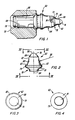
- a cutter bit having a hard tip 62 constructed in accordance with the present invention.
- the cutter bit 60 has a forward body portion 64 and a rearward shank portion 66 which are constructed as a single piece of steel.
- a cylindrical retention spring 68 which is longitudinally slotted and made of resilient material, encompasses the shank portion 66 of the bit 60 and adapts the bit for mounting in a socket 70 of a block 72 which is, in turn, mounted on an excavating drum (not shown).
- the retention spring 68 tightly engages the socket 70 and loosely engages the bit shank portion 66, allowing the bit to rotate during use.
- the hard tip 62 of the present invention is attached on the front end of the forward body portion 64 of the bit 60. Whereas the body and shank portions 64,66 of the bit 60 are constructed as a single piece, the tip 62 is constructed separately and then inserted and either cemented or brazed into a generally concave tapered cavity 74 formed in the front end of the bit body portion 64.
- the hard tip 62 is preferably made of a wear resistant material such as cemented tungsten carbide which includes a cobalt content in the range of 5.3 - 8.0 weight percent, with the preferred cobalt weight percentage being 5.4 - 6.0.
- the tip has a hardness in the range of 87.5 to 89.0 Rockwell A, and preferably 87.8 to 88.6 Rockwell A.
- the hard tip.62 includes an outer tip section 76, an inner flange section 78, and a middle section 80 extending between and merging at its opposite ends with the tip and base sections.
- the flange section 78 has a flange portion defined by a right cylindrical surface 79 and a lower valve seat portion 81 depending below the flange portion 79.
- the lower valve seat portion 81 being similar in shape and configuration to the valve seat portion of the conventional tip, is adapted to be inserted into the tapered cavity 74 of the body portion 64 and then brazed or cemented therein for mounting of the tip 62
- the middle section 80 of the hard tip 62 is uniquely defined by a continuous concave surface of revolution 82.
- the flange portion 79 of the flange section 78 has a diameter which is greater than the maximum diameter of the tip section 76, whereas the middle section 80 has a maximum diameter which is slightly less, but for all practical purposes is substantially equal to the diameter of the cylindrical flange portion 79 and a minimum diameter substantially equal to the maximum diameter of the tip section 76.
- the tip section 76 of the hard tip 62 is defined by a rounded-off end 86 and a frusto-conical surface of revolution 88 merging from the rounded-off end and being generated by a line disposed at predetermined angle from the longitudinal axis 84.
- the concave surface of revolution 82 of the middle section 80 in profile has an outwardly and downwardly sloping configuration generally similar to that of the sides of a bell-shaped surface.
- the tip 62 is fabricated by the same method as described above for the conventional tip. However, now the concave surface of revolution 82 on the middle section 80 of the hard tip 62 is formed by an identically configured surface portion at the mouth of the lower one of the set of forming dies. Thus, the concave surface 82 replaces both the steep frusto-conical surface and sharply-curved surface on the middle section of the conventional tip and by doing so, eliminates the constriction to powder flow in the lower forming die.
- the edge or flat 83 is narrow, being approximately 3-5 mils in width thickness when the tip 62 is formed in its green state, and, after sintering of the tip which causes shrinkage, the flat 83 is narrower. While it is not necessary or preferred in that it adds additional manufacturing expense, the narrow flat 83 may be ground off if desired. Therefore the maximum diameter of the middle section 80 may be less than or equal to the diameter of the flange portion 79.
- the middle concave surface 82 provides the tip 62 of the present invention with a configuration that eliminates the high stress concentrations and decreases the rejection rates experienced heretofore. Further, the concave configuration results in less compaction of the flange section 78 of the tip 62 which allows the tip to be pushed easier out of the die without risk of its own destruction or damage to the die.
- the rounded-off end 86 of the outer tip section 76 has an internal radius from about 0.3048 to about 0.3302 cm, and its frusto-conical surface 88 is generated by a line extending from about 49 to 51 degrees from the longitudinal axis 84.
- the tip section 76 also has a maximum diameter from about 0.9677 to about 0.9931 cm, and a length from about 0.3962 to about 0.4216 cm.
- the cylindrical flange portion 79 has a diameter from about 1.5748 to about 1.6002 cm, and a length from about 0.1651 to about 0.1905 cm.
- the concave surface 82 of the middle section 80 has an external radius 90 from about 1.3843 to about 1.4097 cm.
- the middle section 80 has a length from about 0.9829 to about 1.0083 cm. And the lower valve seat portion 81 of the tip 62 at which the tip is brazed to the bit body 64 is not appreciably different than that same portion of the conventional tip, so it need not be described.
Applications Claiming Priority (2)
| Application Number | Priority Date | Filing Date | Title |
|---|---|---|---|
| US90573086A | 1986-09-09 | 1986-09-09 | |
| US905730 | 1986-09-09 |
Publications (1)
| Publication Number | Publication Date |
|---|---|
| EP0259620A1 true EP0259620A1 (fr) | 1988-03-16 |
Family
ID=25421369
Family Applications (1)
| Application Number | Title | Priority Date | Filing Date |
|---|---|---|---|
| EP87111459A Withdrawn EP0259620A1 (fr) | 1986-09-09 | 1987-08-07 | Outil coupant ayant une pointe pénétrante à section centrale définie comme une surface concave de révolution |
Country Status (8)
| Country | Link |
|---|---|
| EP (1) | EP0259620A1 (fr) |
| JP (1) | JPH0672515B2 (fr) |
| AR (1) | AR243251A1 (fr) |
| BR (1) | BR8704556A (fr) |
| CA (1) | CA1279336C (fr) |
| DK (1) | DK467587A (fr) |
| ES (1) | ES2005287A6 (fr) |
| ZA (1) | ZA876082B (fr) |
Cited By (4)
| Publication number | Priority date | Publication date | Assignee | Title |
|---|---|---|---|---|
| US4893875A (en) * | 1988-12-16 | 1990-01-16 | Caterpillar Inc. | Ground engaging bit having a hardened tip |
| EP0737415A2 (fr) * | 1995-04-15 | 1996-10-16 | RDZ DUTZI GmbH | Dent pour appareil agricole |
| EP0771911A1 (fr) * | 1995-10-31 | 1997-05-07 | BITELLI S.p.A. | Elément actif pour le support d'au moins un outil de fraisage susceptible d'être monté sur des cylindres de fraisage de machines de travail pour l'enlèvement de sols |
| WO2009003233A1 (fr) * | 2007-07-02 | 2009-01-08 | The University Of Sydney | Tête de coupe et son outil |
Families Citing this family (4)
| Publication number | Priority date | Publication date | Assignee | Title |
|---|---|---|---|---|
| US5131725A (en) * | 1990-09-04 | 1992-07-21 | Kennametal Inc. | Rotatable cutting tool having an insert with flanges |
| CN102418523A (zh) * | 2011-12-14 | 2012-04-18 | 宁海县盛源激光科技有限公司 | 一种高耐磨无火花的刀形截齿 |
| GB201320501D0 (en) * | 2013-11-20 | 2014-01-01 | Element Six Gmbh | Strike constructions,picks comprising same and methods for making same |
| DE102018204775A1 (de) * | 2018-03-28 | 2019-10-02 | Thyssenkrupp Ag | Baggerzahn für einen Schaufelradbagger |
Citations (9)
| Publication number | Priority date | Publication date | Assignee | Title |
|---|---|---|---|---|
| US3519309A (en) * | 1965-08-12 | 1970-07-07 | Kennametal Inc | Rotary cone bit retained by captive keeper ring |
| GB1218308A (en) * | 1969-08-11 | 1971-01-06 | Kennametal Inc | Mining tool |
| US4316636A (en) * | 1979-02-01 | 1982-02-23 | Kennametal Inc. | Excavation and road maintenance bits and blocks |
| GB2087949A (en) * | 1980-11-24 | 1982-06-03 | Padley & Venables Ltd | Cutting tools |
| FR2542369A1 (fr) * | 1983-03-10 | 1984-09-14 | Santrade Ltd | Dispositif de montage d'un outil du genre pic |
| EP0121020A1 (fr) * | 1983-03-02 | 1984-10-10 | G-D M & C Limited | Assemblage de trépan de haveuse et porte-trépan |
| US4497520A (en) * | 1983-04-29 | 1985-02-05 | Gte Products Corporation | Rotatable cutting bit |
| GB2166178A (en) * | 1984-10-30 | 1986-04-30 | James Frederick Peaks | Cutting tooth |
| EP0188188A1 (fr) * | 1984-12-19 | 1986-07-23 | VOEST-ALPINE Aktiengesellschaft | Dispositif pour faire jaillir un liquide refroidissant par des buses d'une tête abatteuse |
Family Cites Families (5)
| Publication number | Priority date | Publication date | Assignee | Title |
|---|---|---|---|---|
| US3442342A (en) * | 1967-07-06 | 1969-05-06 | Hughes Tool Co | Specially shaped inserts for compact rock bits,and rolling cutters and rock bits using such inserts |
| AT341978B (de) * | 1976-04-14 | 1978-03-10 | Voest Ag | Rundmeissel |
| US4108260A (en) * | 1977-04-01 | 1978-08-22 | Hughes Tool Company | Rock bit with specially shaped inserts |
| US4254840A (en) * | 1978-10-05 | 1981-03-10 | Reed Tool Company | Drill bit insert |
| SE450259C (sv) * | 1983-03-23 | 1996-07-04 | Sandvik Ab | Verktyg för brytning eller avverkning av fasta material, såsom asfalt |
-
1987
- 1987-08-07 EP EP87111459A patent/EP0259620A1/fr not_active Withdrawn
- 1987-08-17 ZA ZA876082A patent/ZA876082B/xx unknown
- 1987-09-02 ES ES8702549A patent/ES2005287A6/es not_active Expired
- 1987-09-03 BR BR8704556A patent/BR8704556A/pt unknown
- 1987-09-07 AR AR87308646A patent/AR243251A1/es active
- 1987-09-07 JP JP62222174A patent/JPH0672515B2/ja not_active Expired - Lifetime
- 1987-09-08 CA CA000546278A patent/CA1279336C/fr not_active Expired - Lifetime
- 1987-09-08 DK DK467587A patent/DK467587A/da not_active Application Discontinuation
Patent Citations (10)
| Publication number | Priority date | Publication date | Assignee | Title |
|---|---|---|---|---|
| US3519309A (en) * | 1965-08-12 | 1970-07-07 | Kennametal Inc | Rotary cone bit retained by captive keeper ring |
| GB1218308A (en) * | 1969-08-11 | 1971-01-06 | Kennametal Inc | Mining tool |
| US4316636A (en) * | 1979-02-01 | 1982-02-23 | Kennametal Inc. | Excavation and road maintenance bits and blocks |
| GB2087949A (en) * | 1980-11-24 | 1982-06-03 | Padley & Venables Ltd | Cutting tools |
| EP0121020A1 (fr) * | 1983-03-02 | 1984-10-10 | G-D M & C Limited | Assemblage de trépan de haveuse et porte-trépan |
| FR2542369A1 (fr) * | 1983-03-10 | 1984-09-14 | Santrade Ltd | Dispositif de montage d'un outil du genre pic |
| US4497520A (en) * | 1983-04-29 | 1985-02-05 | Gte Products Corporation | Rotatable cutting bit |
| US4497520B1 (fr) * | 1983-04-29 | 1989-01-17 | ||
| GB2166178A (en) * | 1984-10-30 | 1986-04-30 | James Frederick Peaks | Cutting tooth |
| EP0188188A1 (fr) * | 1984-12-19 | 1986-07-23 | VOEST-ALPINE Aktiengesellschaft | Dispositif pour faire jaillir un liquide refroidissant par des buses d'une tête abatteuse |
Cited By (6)
| Publication number | Priority date | Publication date | Assignee | Title |
|---|---|---|---|---|
| US4893875A (en) * | 1988-12-16 | 1990-01-16 | Caterpillar Inc. | Ground engaging bit having a hardened tip |
| EP0737415A2 (fr) * | 1995-04-15 | 1996-10-16 | RDZ DUTZI GmbH | Dent pour appareil agricole |
| EP0737415A3 (fr) * | 1995-04-15 | 1997-03-05 | Rdz Dutzi Gmbh | Dent pour appareil agricole |
| EP0771911A1 (fr) * | 1995-10-31 | 1997-05-07 | BITELLI S.p.A. | Elément actif pour le support d'au moins un outil de fraisage susceptible d'être monté sur des cylindres de fraisage de machines de travail pour l'enlèvement de sols |
| WO2009003233A1 (fr) * | 2007-07-02 | 2009-01-08 | The University Of Sydney | Tête de coupe et son outil |
| EA016278B1 (ru) * | 2007-07-02 | 2012-03-30 | Дзе Юниверсити Оф Сидней | Режущие наконечник и инструмент |
Also Published As
| Publication number | Publication date |
|---|---|
| DK467587D0 (da) | 1987-09-08 |
| AU587141B2 (en) | 1989-08-03 |
| JPS6378993A (ja) | 1988-04-09 |
| AU7717987A (en) | 1988-03-17 |
| CA1279336C (fr) | 1991-01-22 |
| ES2005287A6 (es) | 1989-03-01 |
| JPH0672515B2 (ja) | 1994-09-14 |
| DK467587A (da) | 1989-03-09 |
| AR243251A1 (es) | 1993-07-30 |
| BR8704556A (pt) | 1988-04-26 |
| ZA876082B (en) | 1988-02-25 |
Similar Documents
| Publication | Publication Date | Title |
|---|---|---|
| US5324098A (en) | Cutting tool having hard tip with lobes | |
| US3581835A (en) | Insert for drill bit and manufacture thereof | |
| US7641004B2 (en) | Drill bit | |
| US4276788A (en) | Process for the manufacture of a drill head provided with hard, wear-resistant elements | |
| US4725099A (en) | Rotatable cutting bit | |
| US5667028A (en) | Multiple diamond layer polycrystalline diamond composite cutters | |
| US6241035B1 (en) | Superhard material enhanced inserts for earth-boring bits | |
| US4854405A (en) | Cutting tools | |
| US7048080B2 (en) | Roller cone bits with wear and fracture resistant surface | |
| US5176212A (en) | Combination drill bit | |
| US4323130A (en) | Drill bit | |
| US5496137A (en) | Cutting insert | |
| EP0687797A1 (fr) | Améliorations à ou concernant des éléments converts d'un matériau superdur | |
| EP0259620A1 (fr) | Outil coupant ayant une pointe pénétrante à section centrale définie comme une surface concave de révolution | |
| KR880002597A (ko) | 내마모성 크라운을 갖는 절삭부품 | |
| US5131481A (en) | Insert having a surface of carbide particles | |
| US20090321145A1 (en) | Threaded nozzle for a cutter bit | |
| US4488608A (en) | Rotary stone-cutting head with hardened teeth inserts | |
| US3519092A (en) | Percussion bit | |
| US4865392A (en) | Rotatable cutting bit | |
| GB2041427A (en) | Insert for tool wear surfaces and method of manufacture | |
| US4996919A (en) | Bi-metal feed screw for screw presses | |
| US3326307A (en) | Rock bit roller cone | |
| US4406337A (en) | Insert with locking projection | |
| US3302279A (en) | Method of making ballpoint-pen tips |
Legal Events
| Date | Code | Title | Description |
|---|---|---|---|
| PUAI | Public reference made under article 153(3) epc to a published international application that has entered the european phase |
Free format text: ORIGINAL CODE: 0009012 |
|
| AK | Designated contracting states |
Kind code of ref document: A1 Designated state(s): AT BE DE FR GB IT SE |
|
| 17P | Request for examination filed |
Effective date: 19880426 |
|
| 17Q | First examination report despatched |
Effective date: 19890704 |
|
| STAA | Information on the status of an ep patent application or granted ep patent |
Free format text: STATUS: THE APPLICATION IS DEEMED TO BE WITHDRAWN |
|
| 18D | Application deemed to be withdrawn |
Effective date: 19900116 |
|
| RIN1 | Information on inventor provided before grant (corrected) |
Inventor name: BEACH, WAYNE H. |