EP0259286B1 - Magazine locking means for firearms having a magazine in a pistol handle - Google Patents
Magazine locking means for firearms having a magazine in a pistol handle Download PDFInfo
- Publication number
- EP0259286B1 EP0259286B1 EP87850267A EP87850267A EP0259286B1 EP 0259286 B1 EP0259286 B1 EP 0259286B1 EP 87850267 A EP87850267 A EP 87850267A EP 87850267 A EP87850267 A EP 87850267A EP 0259286 B1 EP0259286 B1 EP 0259286B1
- Authority
- EP
- European Patent Office
- Prior art keywords
- magazine
- catch
- grip
- guide
- locking means
- Prior art date
- Legal status (The legal status is an assumption and is not a legal conclusion. Google has not performed a legal analysis and makes no representation as to the accuracy of the status listed.)
- Expired - Lifetime
Links
Images

Classifications
-
- F—MECHANICAL ENGINEERING; LIGHTING; HEATING; WEAPONS; BLASTING
- F41—WEAPONS
- F41A—FUNCTIONAL FEATURES OR DETAILS COMMON TO BOTH SMALLARMS AND ORDNANCE, e.g. CANNONS; MOUNTINGS FOR SMALLARMS OR ORDNANCE
- F41A17/00—Safety arrangements, e.g. safeties
- F41A17/34—Magazine safeties
- F41A17/38—Magazine mountings, e.g. for locking the magazine in the gun
Definitions
- the present invention generally relates to an improved firearm of the type having a pistol handle or a corresponding weapon part, in which an exchangable magazine is adapted to be introduced and which upon shooting is gripped by the hand of the marksman. More particularly the invention is directed to a magazine locking means for firearms of the said type, in which the pistol grip or a corresponding part of the weapon includes a magazine guide into which the exchangable magazine is adapted to be introduced, and a magazine catch mounted at the front side of the pistol grip for movement between magazine locking and magazine releasing positions, and in the locking position adapted to engage a projection part at the front side of said magazine.
- the invention has been made as a result of the development of hand firearms like pistols, machine pistols and other pistol-like weapons having magazines which have to be quickly exchanged, but it is obvious that the invention is as well useful also for many other types of firearms having exchangable magazines in the part of the firearm which during shooting is gripped by the hand of the marksman, whereby a grip catch is pressed thereby releasing the weapon for firing.
- the magazine catch is placed on the side of the pistol handle, generally at the left side, and hence the magazine catch can be actuated by the thumb of the firing hand only by right-handed marksmen.
- the patent DE-82 2.014.328 discloses a pistol having a magazine which is mounted for actuation inside the trigger guard and behind the trigger. Also this magazine catch can only be actuated by one finger on the shooting hand.
- the patent US-A 3,372,506 discloses a magazine catch according to the preamble of claim 1 and provided at the lowermost part of the pistol grip and which can only be reached by the thumb of the shooting hand of the marksman, and which is designed so that the marksman has to use both hands to release the magazine, namely one hand for holding the pistol grip and the other hand for pulling the magazine catch outwards.
- the magazine catch engages a recess provided directly in a relatively thin magazine wall.
- This structure is useful for small and light-weight magazines but the structure is considered too weak for large and heavy magazines.
- the invention is intended to provide a magazine catch for the above mentioned types of firearms, which magazine catch is co-ordinated to the grip catch, which can be actuated by the thumb of the firing hand both by right-handed and by left-handed marksmen thereby enabling the quickest possible exchange of magazines, and which is designed for effectively holding even large and heavy magazines, for instance magazines for machine pistols.
- the said objects are fulfilled by means of some few and easily manufactured pieces.
- the invention is mainly characterized in that the magazine catch comprises an elongated plate extending along the front side of the magazine guide and which plate is hingely connected to the pistol grip about a cross pin at its lower end for pivotal movement between said locking and releasing positions, and which plate has, at the upper portion thereof, grab parts projecting at opposite sides of the pistol grip, each of said grab parts being located for being easily reached by the thumb of the marksman both at the left side and the right side of the pistol grip and without the need for the marksman to change hand grip, and any one of said grab parts being alternatively usable independently of the other grab part to pivotally move the magazine catch to said releasing position thereby releasing said magazine from the magazine guide by a thumb actuation straight forwardly of at least one of said grab parts.
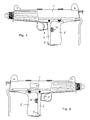
- FIG. 1 and 2 show a machine pistol seen from the left side and from the right side respectively.
- Figure 3 shows, like in figure 1, a sideview of a machine pistol, partly in a cross section, having a magazine catch according to the invention.
- Figure 4 shows more in detail a cross section view through the magazine catch according to the invention, and the co-ordination thereof with the grip catch and the magazine, and figure 5 is a perspective view of the magazine catch.
- the sub machine gun shown in figures 1-3 is of known typ and therefore all parts thereof will not be described in detail.
- the firearm comprises a receiver 1 having a not-illustrated lock bolt and a pistol grip 2 connected to the receiver 1 and having a trigger and a grip safety 4.
- An exchangable magazine 5 is adapted to be introduced in a magazine guide 6 provided in the pistol grip 2 and to be locked in this position by a magazine catch.
- the grip safety 4 is in the form a curved handle which is rotatably mounted on a cross pin 7 of a grip safety bracket 8.
- the magazine catch 9 is rotatably mounted on the same pin 7.
- the magazine catch comprises at its bottom a tubular carrier 10, an intermediate plain portion 11 and at its top a yoke-formed part 12 having fold out grab portions 13 and 14.
- the yoke part 12 is integral with the intermediate portion 11 over a web 15, by means of which the yoke part of the catch extends into the magazine guide 6 and into the area of magazine introduction.
- the largest part of the magazine catch 9 is enclosed between the grip safety 4 and the front wall of the magazine guide 6.
- the upper part of the catch which is formed as a yoke having grab parts 13 and 14 in the form of double folded plate parts projecting on opposite sides thereof, encloses the side walls of the magazine catch 6.
- the grab parts 13 and 14 of the catch 9 are readily accessable by the thumb of the marksman on the left side for right-handed marksmen and on the right side for left-handed marksmen.
- the upper edge 16 of the magazine catch 9 provides a stop edge for engagement with a lock plate 17 which is welded or otherwise fixed mounted on the front side of the magazine.
- the grip safety 4 and the magazine catch 9 are rotably mounted on the same pin 7, and a pressure spring 18 is mounted between the grip safety 4 and the plain intermediate part 11 of the magazine catch. Said spring 18 biasses the two parts in opposite directions. part.
- the grip safety is blocked from moving forwardly by the trigger or any other part of the firearm, and the magazine catch, in turn, is blocked from moving rearwardly by the magazine guide, whereby the grip safety normally takes a firing blocking position and the magazine guide normally takes a magazine locking position.
- the magazine For introducing a magazine 5 in the magazine guide 6 of the pistol grip the magazine is just pushed right up, whereby the upper edge thereof, by actuating the web 15 of the catch, moves the catch out until the lock plate 17 of the magazine has passed the upper edge 16 of the catch, whereby the catch snaps back and locks the magazine against the bottom edge of the lock palte 17.
- the magazine catch is pressed forwardly by the thumb of the firing hand, that is the thumb of the firing hand of a right-handed marksman or of a left-handed marksman, whereby the upper edge 16 of the catch is released from the lock plate 17 of the magazine, and the magazine 5, which slides easily in its guide, drops out of the magazine guide.
- This can be done by using only one hand without the need of moving the hand from pistol grip and even without moving the firearm from its adjusted firing position.
- the marksman can get a new magazine and move same as far into the magazine guide that the upper edge 16 of the catch snaps into position under the lock plate 17 of the magazine.
Landscapes
- Engineering & Computer Science (AREA)
- General Engineering & Computer Science (AREA)
- Toys (AREA)
- Portable Nailing Machines And Staplers (AREA)
- Labeling Devices (AREA)
- Medicines Containing Antibodies Or Antigens For Use As Internal Diagnostic Agents (AREA)
- Acyclic And Carbocyclic Compounds In Medicinal Compositions (AREA)
- Medicines That Contain Protein Lipid Enzymes And Other Medicines (AREA)
- Details Of Rigid Or Semi-Rigid Containers (AREA)
- Vending Machines For Individual Products (AREA)
- Pyrane Compounds (AREA)
- Lock And Its Accessories (AREA)
- Secondary Cells (AREA)
- Mechanical Pencils And Projecting And Retracting Systems Therefor, And Multi-System Writing Instruments (AREA)
- Sampling And Sample Adjustment (AREA)
Abstract
Description
- The present invention generally relates to an improved firearm of the type having a pistol handle or a corresponding weapon part, in which an exchangable magazine is adapted to be introduced and which upon shooting is gripped by the hand of the marksman. More particularly the invention is directed to a magazine locking means for firearms of the said type, in which the pistol grip or a corresponding part of the weapon includes a magazine guide into which the exchangable magazine is adapted to be introduced, and a magazine catch mounted at the front side of the pistol grip for movement between magazine locking and magazine releasing positions, and in the locking position adapted to engage a projection part at the front side of said magazine.
- The invention has been made as a result of the development of hand firearms like pistols, machine pistols and other pistol-like weapons having magazines which have to be quickly exchanged, but it is obvious that the invention is as well useful also for many other types of firearms having exchangable magazines in the part of the firearm which during shooting is gripped by the hand of the marksman, whereby a grip catch is pressed thereby releasing the weapon for firing.
- In conventional firearms like a machine pistol the magazine catch is usually located so that it can be actuated by the hand which is gripping the pistol handle, in other words the firing hand. This makes an exchange of the magazine difficult, and above all it prolonges the time needed for exchange of magazine, and this is a serious disadvantage in critical situations. For pistols, which have a rather little magazine capacity, structural solutions have since long been looked for in order to provide quick exchanges of magazines. Said firearms therefore often are formed with a magazine catch which can be actuated by the thumb of the "firing hand" at the same time as the "support hand" seizes and introduces a new magazine in the magazine guide of the pistol handle.
- In many known weapons, like the weapon disclosed in the patent DE-A1 2.618.074, the magazine catch is placed on the side of the pistol handle, generally at the left side, and hence the magazine catch can be actuated by the thumb of the firing hand only by right-handed marksmen.
- The patent DE-82 2.014.328 discloses a pistol having a magazine which is mounted for actuation inside the trigger guard and behind the trigger. Also this magazine catch can only be actuated by one finger on the shooting hand.
- The patent US-A 3,372,506 discloses a magazine catch according to the preamble of claim 1 and provided at the lowermost part of the pistol grip and which can only be reached by the thumb of the shooting hand of the marksman, and which is designed so that the marksman has to use both hands to release the magazine, namely one hand for holding the pistol grip and the other hand for pulling the magazine catch outwards.
- In many known apparatus the magazine catch engages a recess provided directly in a relatively thin magazine wall. This structure is useful for small and light-weight magazines but the structure is considered too weak for large and heavy magazines.
- The invention is intended to provide a magazine catch for the above mentioned types of firearms, which magazine catch is co-ordinated to the grip catch, which can be actuated by the thumb of the firing hand both by right-handed and by left-handed marksmen thereby enabling the quickest possible exchange of magazines, and which is designed for effectively holding even large and heavy magazines, for instance magazines for machine pistols.
- The said objects are fulfilled by means of some few and easily manufactured pieces. The invention is mainly characterized in that the magazine catch comprises an elongated plate extending along the front side of the magazine guide and which plate is hingely connected to the pistol grip about a cross pin at its lower end for pivotal movement between said locking and releasing positions, and which plate has, at the upper portion thereof, grab parts projecting at opposite sides of the pistol grip, each of said grab parts being located for being easily reached by the thumb of the marksman both at the left side and the right side of the pistol grip and without the need for the marksman to change hand grip, and any one of said grab parts being alternatively usable independently of the other grab part to pivotally move the magazine catch to said releasing position thereby releasing said magazine from the magazine guide by a thumb actuation straight forwardly of at least one of said grab parts.
- Further characteristics of the invention and advantages thereof will be evident from the following specification and from the appended claims.
- Now the invention will be described more closely with reference to the accompanying drawings, in which figures 1 and 2 show a machine pistol seen from the left side and from the right side respectively. Figure 3 shows, like in figure 1, a sideview of a machine pistol, partly in a cross section, having a magazine catch according to the invention. Figure 4 shows more in detail a cross section view through the magazine catch according to the invention, and the co-ordination thereof with the grip catch and the magazine, and figure 5 is a perspective view of the magazine catch.
- The sub machine gun shown in figures 1-3 is of known typ and therefore all parts thereof will not be described in detail. The firearm comprises a receiver 1 having a not-illustrated lock bolt and a
pistol grip 2 connected to the receiver 1 and having a trigger and agrip safety 4. Anexchangable magazine 5 is adapted to be introduced in amagazine guide 6 provided in thepistol grip 2 and to be locked in this position by a magazine catch. - The
grip safety 4 is in the form a curved handle which is rotatably mounted on across pin 7 of agrip safety bracket 8. Themagazine catch 9 is rotatably mounted on thesame pin 7. As best shown in figure 5 the magazine catch comprises at its bottom atubular carrier 10, an intermediateplain portion 11 and at its top a yoke-formedpart 12 having fold outgrab portions yoke part 12 is integral with theintermediate portion 11 over aweb 15, by means of which the yoke part of the catch extends into themagazine guide 6 and into the area of magazine introduction. - The largest part of the
magazine catch 9 is enclosed between thegrip safety 4 and the front wall of themagazine guide 6. The upper part of the catch, which is formed as a yoke havinggrab parts magazine catch 6. Thegrab parts catch 9 are readily accessable by the thumb of the marksman on the left side for right-handed marksmen and on the right side for left-handed marksmen. Theupper edge 16 of themagazine catch 9 provides a stop edge for engagement with alock plate 17 which is welded or otherwise fixed mounted on the front side of the magazine. - As explained above the
grip safety 4 and themagazine catch 9 are rotably mounted on thesame pin 7, and apressure spring 18 is mounted between thegrip safety 4 and the plainintermediate part 11 of the magazine catch. Saidspring 18 biasses the two parts in opposite directions. part. The grip safety is blocked from moving forwardly by the trigger or any other part of the firearm, and the magazine catch, in turn, is blocked from moving rearwardly by the magazine guide, whereby the grip safety normally takes a firing blocking position and the magazine guide normally takes a magazine locking position. - For introducing a
magazine 5 in themagazine guide 6 of the pistol grip the magazine is just pushed right up, whereby the upper edge thereof, by actuating theweb 15 of the catch, moves the catch out until thelock plate 17 of the magazine has passed theupper edge 16 of the catch, whereby the catch snaps back and locks the magazine against the bottom edge of thelock palte 17. - For exchanging magazine the magazine catch is pressed forwardly by the thumb of the firing hand, that is the thumb of the firing hand of a right-handed marksman or of a left-handed marksman, whereby the
upper edge 16 of the catch is released from thelock plate 17 of the magazine, and themagazine 5, which slides easily in its guide, drops out of the magazine guide. This can be done by using only one hand without the need of moving the hand from pistol grip and even without moving the firearm from its adjusted firing position. With the other hand the marksman can get a new magazine and move same as far into the magazine guide that theupper edge 16 of the catch snaps into position under thelock plate 17 of the magazine. - It is to be understood that the above description and the embodiment of the invention shown in the drawings is only an illustrating example, and that many different variations and modification may be presented within the scope of the appended claims.
Claims (6)
- Magazine locking means for firearms of the type having a pistol grip (2) or a corresponding part which is grasped by the firing hand of the marksman and which which includes a magazine guide (6) into which an exchangable magazine (5) is adapted to be introduced, and a magazine catch (9) mounted at the front side of the pistol grip (2) for movement between magazine locking and magazine relasing positions, and in the locking position adapted to engage a projection part (17) at the front side of said magazine, characterized in
that the magazine catch (9) comprises an elongated plate extending along the front side of the magazine guide (6) and which plate is hingely connected to said pistol grip (2) about a cross pin (7) at its lower end (10) for pivotal movement between said locking and releasing positions,
and which plate has, at the upper portion thereof, grab parts (13, 14) projecting at opposite sides of the pistol grip (2),
each of said grab parts (13, 14) being located for being easily reached by the thumb of the marksman both at the left side and the right side of the pistol grip (2) and without the need for the marksman to change hand grip and being alternatively usable independently of the other of said grab parts (13, 14) to pivotally move the magazine catch (5) to said releasing position thereby releasing said magazine from said magazine guide by a thumb actuation straight forwardly of at least one of said grab parts (13, 14). - Magazine locking means according to claim 1, characterized in that the magazine catch (5) is an integral plate having a lower tubular hinge part (10), a plain intermediate part (11) and an upper yoke part (12) which, with an even side thereif, is integral with the intermediate part (11) via a web part (15), so that said yoke part (12) can be introduced through the magazine guide (6) and into an introduction path for the magazine (5).
- Magazine locking means according to claim 2, characterized in that the grab parts (13, 14) project at opposite sides from the plain portion of the yoke part (12) on each side of the magazine guide (6) thereby forming holds for releasing the catch from the magazine (5) which is introduced in the guide (6).
- Magazine locking means according to any of the preceding claims, characterized in that the firearm has a grip safety (4) at the front side of the pistol grip (2), which grip safety defines the front edge of the pistol grip (2) and encloses the front edge of the magazine guide (6), whereby the magazine catch (9) is partially enclosed by said grip safety (4).
- Magazine locking means according to claim 4, characterized in that a pressure spring (18) is mounted between the grip safety (4) and the magazine catch (9) to bias said grip safety (4) and said magazine catch in opposite directions.
- Magazine locking means according to claims 4 and 5, characterized in that the grip safety (4) and the magazine catch (9) are rotatable about a common cross pin (7) provided at the lower edge of the front side of the magazine guide (6).
Priority Applications (1)
| Application Number | Priority Date | Filing Date | Title |
|---|---|---|---|
| AT87850267T ATE62341T1 (en) | 1986-09-05 | 1987-09-03 | MAGAZINE HOLDING DEVICE FOR WEAPONS WITH A MAGAZINE IN THE HANDLE. |
Applications Claiming Priority (2)
| Application Number | Priority Date | Filing Date | Title |
|---|---|---|---|
| SE8603734A SE459526B (en) | 1986-09-05 | 1986-09-05 | MAGAZINE SAVINGS FOR ELECTRIC WEAPONS WITH MACHINE IN GUN |
| SE8603734 | 1986-09-05 |
Publications (2)
| Publication Number | Publication Date |
|---|---|
| EP0259286A1 EP0259286A1 (en) | 1988-03-09 |
| EP0259286B1 true EP0259286B1 (en) | 1991-04-03 |
Family
ID=20365501
Family Applications (1)
| Application Number | Title | Priority Date | Filing Date |
|---|---|---|---|
| EP87850267A Expired - Lifetime EP0259286B1 (en) | 1986-09-05 | 1987-09-03 | Magazine locking means for firearms having a magazine in a pistol handle |
Country Status (14)
| Country | Link |
|---|---|
| US (1) | US4798018A (en) |
| EP (1) | EP0259286B1 (en) |
| CN (1) | CN1011262B (en) |
| AT (1) | ATE62341T1 (en) |
| BR (1) | BR8704638A (en) |
| CA (1) | CA1291353C (en) |
| DE (1) | DE3769045D1 (en) |
| ES (1) | ES2021098B3 (en) |
| FI (1) | FI873847A7 (en) |
| GR (1) | GR3001812T3 (en) |
| HU (1) | HU197439B (en) |
| SE (1) | SE459526B (en) |
| SG (1) | SG58891G (en) |
| YU (1) | YU164987A (en) |
Families Citing this family (19)
| Publication number | Priority date | Publication date | Assignee | Title |
|---|---|---|---|---|
| US5357703A (en) * | 1993-01-13 | 1994-10-25 | Ram-Line, Inc. | Cartridge magazine having a metal body used with a plastic firearm |
| DE19507012C2 (en) * | 1995-03-01 | 1998-10-08 | Walther Carl Gmbh | Magazine holder |
| US6412207B1 (en) | 1998-06-24 | 2002-07-02 | Caleb Clark Crye | Firearm safety and control system |
| US6240669B1 (en) | 1999-04-26 | 2001-06-05 | Frank A Spaniel | Magazine safety |
| US20040011344A1 (en) * | 2001-11-23 | 2004-01-22 | Npf Limited | Paintball markers |
| US6874266B1 (en) * | 2003-12-01 | 2005-04-05 | Larry Shuming Kong | Insert for storing a firearm cartridge within cavity of handgun grip |
| AT500667B1 (en) * | 2003-12-09 | 2006-11-15 | Gen Headquarters Of The Armed | PISTOL |
| US7958661B2 (en) * | 2009-04-16 | 2011-06-14 | Strayer Sandy L | Firearm having universal magazine release mechanism |
| EP2336705B1 (en) * | 2009-12-17 | 2012-07-11 | SIG SAUER GmbH | Magazine holder |
| AT511266B1 (en) * | 2011-04-04 | 2012-10-15 | Merkel Jagd Und Sportwaffen Gmbh | PISTOL WITH MAGAZINE HOLDER |
| CA2783364A1 (en) * | 2011-07-18 | 2013-01-18 | Richard Clinton Truman | Ammunition magazine |
| US9383152B2 (en) | 2014-10-24 | 2016-07-05 | Magpul Industries Corp. | Weapon magazine |
| USD810223S1 (en) | 2015-10-08 | 2018-02-13 | Magpul Industries Corp. | Magazine for a firearm |
| USD812176S1 (en) | 2016-05-05 | 2018-03-06 | Magpul Industries Corp. | Magazine |
| DE102017101118A1 (en) * | 2017-01-20 | 2018-07-26 | Steiner-Optik Gmbh | Communication system for transmitting captured object information between at least two communication partners |
| US10900742B2 (en) * | 2018-04-13 | 2021-01-26 | Mcp Ip, Llc | Stabilizing grip for shooting device |
| US10852099B2 (en) * | 2018-04-13 | 2020-12-01 | Mcp Ip, Llc | Stabilizing grip for shooting device |
| US11408707B2 (en) * | 2020-01-21 | 2022-08-09 | Gun Guardian Llc | Firearm adapter with removable grip assembly |
| CN113847840A (en) * | 2021-10-13 | 2021-12-28 | 重庆建设工业(集团)有限责任公司 | Pistol magazine locking and releasing mechanism capable of being operated quickly by both left hand and right hand |
Family Cites Families (13)
| Publication number | Priority date | Publication date | Assignee | Title |
|---|---|---|---|---|
| DE279889C (en) * | ||||
| US804985A (en) * | 1904-10-01 | 1905-11-21 | William D Condit | Firearm. |
| US954797A (en) * | 1907-11-04 | 1910-04-12 | Thomas Darlington | Automatic gun. |
| US1168024A (en) * | 1914-06-22 | 1916-01-11 | Savage Arms Company | Firearm. |
| US1226478A (en) * | 1915-08-06 | 1917-05-15 | Berkley C Stone | Automatic firearm. |
| US3372506A (en) * | 1966-05-13 | 1968-03-12 | High Standard Mfg Corp | Magazine catch for firearms |
| US3574264A (en) * | 1969-07-14 | 1971-04-13 | Ernest P Simmons Sr | Magazine assembly for automatic rifles |
| DE2014328C3 (en) * | 1970-03-25 | 1975-11-13 | Rheinmetall Gmbh, 4000 Duesseldorf | Magazine holder and release mechanism on handguns |
| DE2618074A1 (en) * | 1976-04-24 | 1977-11-10 | Hermann Ing Grad Lieb | Quick magazine release device for automatic pistols - has thumb actuated magazine release ensuring rapid magazine change |
| DE2627641C2 (en) * | 1976-06-19 | 1983-11-10 | Heckler & Koch Gmbh, 7238 Oberndorf | Handle cocking self-loading pistol |
| IT1090108B (en) * | 1977-10-24 | 1985-06-18 | Beretta Armi Spa | REVERSIBLE SLIDING STOP HOOK FOR PISTOL MAGAZINES |
| DE2905770C2 (en) * | 1979-02-15 | 1984-01-05 | Carl Walther Gmbh, 7900 Ulm | Magazine release |
| GB2137321B (en) * | 1983-03-28 | 1986-08-20 | David Edward Smith | Ambidextrous cartridge magazine retaining catch for self loading fire arms |
-
1986
- 1986-09-05 SE SE8603734A patent/SE459526B/en not_active IP Right Cessation
-
1987
- 1987-09-03 ES ES87850267T patent/ES2021098B3/en not_active Expired - Lifetime
- 1987-09-03 US US07/092,462 patent/US4798018A/en not_active Expired - Fee Related
- 1987-09-03 EP EP87850267A patent/EP0259286B1/en not_active Expired - Lifetime
- 1987-09-03 DE DE8787850267T patent/DE3769045D1/en not_active Expired - Lifetime
- 1987-09-03 AT AT87850267T patent/ATE62341T1/en not_active IP Right Cessation
- 1987-09-04 YU YU01649/87A patent/YU164987A/en unknown
- 1987-09-04 FI FI873847A patent/FI873847A7/en not_active IP Right Cessation
- 1987-09-04 BR BR8704638A patent/BR8704638A/en not_active IP Right Cessation
- 1987-09-04 CA CA000546230A patent/CA1291353C/en not_active Expired - Lifetime
- 1987-09-04 HU HU873969A patent/HU197439B/en unknown
- 1987-09-05 CN CN87106176A patent/CN1011262B/en not_active Expired
-
1991
- 1991-04-19 GR GR91400501T patent/GR3001812T3/en unknown
- 1991-07-24 SG SG588/91A patent/SG58891G/en unknown
Also Published As
| Publication number | Publication date |
|---|---|
| FI873847L (en) | 1988-03-06 |
| DE3769045D1 (en) | 1991-05-08 |
| YU164987A (en) | 1990-06-30 |
| SG58891G (en) | 1991-08-23 |
| CN1011262B (en) | 1991-01-16 |
| HU197439B (en) | 1989-03-28 |
| US4798018A (en) | 1989-01-17 |
| CA1291353C (en) | 1991-10-29 |
| FI873847A7 (en) | 1988-03-06 |
| SE459526B (en) | 1989-07-10 |
| ES2021098B3 (en) | 1991-10-16 |
| BR8704638A (en) | 1988-04-26 |
| HUT45142A (en) | 1988-05-30 |
| EP0259286A1 (en) | 1988-03-09 |
| CN87106176A (en) | 1988-10-19 |
| SE8603734D0 (en) | 1986-09-05 |
| FI873847A0 (en) | 1987-09-04 |
| ATE62341T1 (en) | 1991-04-15 |
| GR3001812T3 (en) | 1992-11-23 |
| SE8603734L (en) | 1988-03-06 |
Similar Documents
| Publication | Publication Date | Title |
|---|---|---|
| US4798018A (en) | Magazine locking means for firearms having a magazine in a pistol grip | |
| US4326353A (en) | Magazine catch release for a hand firearm | |
| EP0834052B1 (en) | Ambidextrous magazine release mechanism for firearms | |
| US4463654A (en) | Conversion kit for assault rifle and converted rifle of compact configuration | |
| CA2379739C (en) | Lockable safety for firearms | |
| US4689908A (en) | Holster and handgrip extension for miniature handguns | |
| US4479480A (en) | Crossbow trigger mechanism | |
| CA2474731A1 (en) | High security holster assembly and enclosure system | |
| US4833970A (en) | Submachine gun | |
| EP1210559B1 (en) | Locking mechanism for firearms | |
| CA1233050A (en) | Machine pistol with retarded blowback | |
| US7395747B2 (en) | Breechblock stops for firearms and methods of operating the same | |
| IL120415A (en) | Loading lever mechanism for a hand-held firearm | |
| US4621445A (en) | Weapon with locking trigger | |
| US6952895B1 (en) | Magazine disconnect safety | |
| US4569145A (en) | Inactivating selector arrangement for bolt action firearms | |
| US20060265925A1 (en) | Locking levers for removable ammunition magazines for firearms and methods of operating the same | |
| US5992075A (en) | Repeating gun having an axially guided repeating unit | |
| US4514923A (en) | Trigger actuator | |
| US5649383A (en) | Barrel retaining device for firearms | |
| WO2022034014A1 (en) | Magazine latch | |
| US5070634A (en) | Left-handed slide catch | |
| WO1992013249A1 (en) | Gun lock assembly | |
| US11480403B2 (en) | Magazine latch | |
| US5700967A (en) | Interlocking mechanism for a self-loading weapon |
Legal Events
| Date | Code | Title | Description |
|---|---|---|---|
| PUAI | Public reference made under article 153(3) epc to a published international application that has entered the european phase |
Free format text: ORIGINAL CODE: 0009012 |
|
| AK | Designated contracting states |
Kind code of ref document: A1 Designated state(s): AT BE CH DE ES FR GB GR IT LI NL SE |
|
| 17P | Request for examination filed |
Effective date: 19880528 |
|
| 17Q | First examination report despatched |
Effective date: 19890811 |
|
| ITF | It: translation for a ep patent filed | ||
| GRAA | (expected) grant |
Free format text: ORIGINAL CODE: 0009210 |
|
| AK | Designated contracting states |
Kind code of ref document: B1 Designated state(s): AT BE CH DE ES FR GB GR IT LI NL SE |
|
| PG25 | Lapsed in a contracting state [announced via postgrant information from national office to epo] |
Ref country code: SE Effective date: 19910403 |
|
| REF | Corresponds to: |
Ref document number: 62341 Country of ref document: AT Date of ref document: 19910415 Kind code of ref document: T |
|
| REF | Corresponds to: |
Ref document number: 3769045 Country of ref document: DE Date of ref document: 19910508 |
|
| ET | Fr: translation filed | ||
| PGFP | Annual fee paid to national office [announced via postgrant information from national office to epo] |
Ref country code: GR Payment date: 19910830 Year of fee payment: 5 |
|
| PGFP | Annual fee paid to national office [announced via postgrant information from national office to epo] |
Ref country code: GB Payment date: 19910902 Year of fee payment: 5 |
|
| PGFP | Annual fee paid to national office [announced via postgrant information from national office to epo] |
Ref country code: ES Payment date: 19910913 Year of fee payment: 5 |
|
| PGFP | Annual fee paid to national office [announced via postgrant information from national office to epo] |
Ref country code: FR Payment date: 19910927 Year of fee payment: 5 Ref country code: AT Payment date: 19910927 Year of fee payment: 5 |
|
| PGFP | Annual fee paid to national office [announced via postgrant information from national office to epo] |
Ref country code: NL Payment date: 19910930 Year of fee payment: 5 |
|
| PGFP | Annual fee paid to national office [announced via postgrant information from national office to epo] |
Ref country code: BE Payment date: 19911003 Year of fee payment: 5 |
|
| PGFP | Annual fee paid to national office [announced via postgrant information from national office to epo] |
Ref country code: DE Payment date: 19911022 Year of fee payment: 5 |
|
| PGFP | Annual fee paid to national office [announced via postgrant information from national office to epo] |
Ref country code: CH Payment date: 19911127 Year of fee payment: 5 |
|
| PLBE | No opposition filed within time limit |
Free format text: ORIGINAL CODE: 0009261 |
|
| STAA | Information on the status of an ep patent application or granted ep patent |
Free format text: STATUS: NO OPPOSITION FILED WITHIN TIME LIMIT |
|
| 26N | No opposition filed | ||
| REG | Reference to a national code |
Ref country code: GR Ref legal event code: FG4A Free format text: 3001812 |
|
| PG25 | Lapsed in a contracting state [announced via postgrant information from national office to epo] |
Ref country code: GB Effective date: 19920903 Ref country code: AT Effective date: 19920903 |
|
| PG25 | Lapsed in a contracting state [announced via postgrant information from national office to epo] |
Ref country code: ES Free format text: LAPSE BECAUSE OF EXPIRATION OF PROTECTION Effective date: 19920904 |
|
| PG25 | Lapsed in a contracting state [announced via postgrant information from national office to epo] |
Ref country code: LI Effective date: 19920930 Ref country code: CH Effective date: 19920930 Ref country code: BE Effective date: 19920930 |
|
| BERE | Be: lapsed |
Owner name: JOHANSSON BERTIL Effective date: 19920930 |
|
| PG25 | Lapsed in a contracting state [announced via postgrant information from national office to epo] |
Ref country code: GR Free format text: THE PATENT HAS BEEN ANNULLED BY A DECISION OF A NATIONAL AUTHORITY Effective date: 19930331 |
|
| PG25 | Lapsed in a contracting state [announced via postgrant information from national office to epo] |
Ref country code: NL Effective date: 19930401 |
|
| GBPC | Gb: european patent ceased through non-payment of renewal fee |
Effective date: 19920903 |
|
| NLV4 | Nl: lapsed or anulled due to non-payment of the annual fee | ||
| PG25 | Lapsed in a contracting state [announced via postgrant information from national office to epo] |
Ref country code: FR Effective date: 19930528 |
|
| REG | Reference to a national code |
Ref country code: CH Ref legal event code: PL |
|
| PG25 | Lapsed in a contracting state [announced via postgrant information from national office to epo] |
Ref country code: DE Effective date: 19930602 |
|
| REG | Reference to a national code |
Ref country code: FR Ref legal event code: ST |
|
| REG | Reference to a national code |
Ref country code: GR Ref legal event code: MM2A Free format text: 3001812 |
|
| REG | Reference to a national code |
Ref country code: ES Ref legal event code: FD2A Effective date: 19990601 |
|
| PG25 | Lapsed in a contracting state [announced via postgrant information from national office to epo] |
Ref country code: IT Free format text: LAPSE BECAUSE OF NON-PAYMENT OF DUE FEES;WARNING: LAPSES OF ITALIAN PATENTS WITH EFFECTIVE DATE BEFORE 2007 MAY HAVE OCCURRED AT ANY TIME BEFORE 2007. THE CORRECT EFFECTIVE DATE MAY BE DIFFERENT FROM THE ONE RECORDED. Effective date: 20050903 |